EP0688934A2 - Vitrage isolant - Google Patents
Vitrage isolant Download PDFInfo
- Publication number
- EP0688934A2 EP0688934A2 EP95113318A EP95113318A EP0688934A2 EP 0688934 A2 EP0688934 A2 EP 0688934A2 EP 95113318 A EP95113318 A EP 95113318A EP 95113318 A EP95113318 A EP 95113318A EP 0688934 A2 EP0688934 A2 EP 0688934A2
- Authority
- EP
- European Patent Office
- Prior art keywords
- frame
- mounting bar
- clip
- anchor
- spacer
- Prior art date
- Legal status (The legal status is an assumption and is not a legal conclusion. Google has not performed a legal analysis and makes no representation as to the accuracy of the status listed.)
- Withdrawn
Links
- 239000011521 glass Substances 0.000 title claims abstract description 23
- 125000006850 spacer group Chemical group 0.000 claims abstract description 44
- 230000002093 peripheral effect Effects 0.000 claims abstract description 9
- 230000008878 coupling Effects 0.000 claims abstract 2
- 238000010168 coupling process Methods 0.000 claims abstract 2
- 238000005859 coupling reaction Methods 0.000 claims abstract 2
- 238000004873 anchoring Methods 0.000 claims 1
- 239000000565 sealant Substances 0.000 description 45
- 239000002274 desiccant Substances 0.000 description 18
- 239000000463 material Substances 0.000 description 12
- 239000012943 hotmelt Substances 0.000 description 10
- 238000005452 bending Methods 0.000 description 8
- 239000012812 sealant material Substances 0.000 description 7
- 238000010276 construction Methods 0.000 description 6
- 230000008595 infiltration Effects 0.000 description 6
- 238000001764 infiltration Methods 0.000 description 6
- XLYOFNOQVPJJNP-UHFFFAOYSA-N water Chemical compound O XLYOFNOQVPJJNP-UHFFFAOYSA-N 0.000 description 6
- 230000004888 barrier function Effects 0.000 description 4
- 238000009833 condensation Methods 0.000 description 4
- 230000005494 condensation Effects 0.000 description 4
- 238000007789 sealing Methods 0.000 description 4
- 239000011261 inert gas Substances 0.000 description 3
- XKRFYHLGVUSROY-UHFFFAOYSA-N Argon Chemical compound [Ar] XKRFYHLGVUSROY-UHFFFAOYSA-N 0.000 description 2
- 230000006978 adaptation Effects 0.000 description 2
- 229910052782 aluminium Inorganic materials 0.000 description 2
- XAGFODPZIPBFFR-UHFFFAOYSA-N aluminium Chemical compound [Al] XAGFODPZIPBFFR-UHFFFAOYSA-N 0.000 description 2
- 229910052751 metal Inorganic materials 0.000 description 2
- 239000002184 metal Substances 0.000 description 2
- 238000012986 modification Methods 0.000 description 2
- 230000004048 modification Effects 0.000 description 2
- 229920002635 polyurethane Polymers 0.000 description 2
- 239000004814 polyurethane Substances 0.000 description 2
- 230000003313 weakening effect Effects 0.000 description 2
- 239000010963 304 stainless steel Substances 0.000 description 1
- 229920002367 Polyisobutene Polymers 0.000 description 1
- 229910000589 SAE 304 stainless steel Inorganic materials 0.000 description 1
- 229910000831 Steel Inorganic materials 0.000 description 1
- 230000009471 action Effects 0.000 description 1
- 229910052786 argon Inorganic materials 0.000 description 1
- 238000000429 assembly Methods 0.000 description 1
- 230000000712 assembly Effects 0.000 description 1
- 230000003190 augmentative effect Effects 0.000 description 1
- 230000009286 beneficial effect Effects 0.000 description 1
- 230000015572 biosynthetic process Effects 0.000 description 1
- 239000011248 coating agent Substances 0.000 description 1
- 238000000576 coating method Methods 0.000 description 1
- 238000004891 communication Methods 0.000 description 1
- 239000002131 composite material Substances 0.000 description 1
- 230000001419 dependent effect Effects 0.000 description 1
- 230000001066 destructive effect Effects 0.000 description 1
- 230000000694 effects Effects 0.000 description 1
- 238000001125 extrusion Methods 0.000 description 1
- 239000007789 gas Substances 0.000 description 1
- 238000009434 installation Methods 0.000 description 1
- 239000012212 insulator Substances 0.000 description 1
- 238000012423 maintenance Methods 0.000 description 1
- 238000004519 manufacturing process Methods 0.000 description 1
- 239000011159 matrix material Substances 0.000 description 1
- 239000000203 mixture Substances 0.000 description 1
- 229920001296 polysiloxane Polymers 0.000 description 1
- 229920001021 polysulfide Polymers 0.000 description 1
- 239000005077 polysulfide Substances 0.000 description 1
- 150000008117 polysulfides Polymers 0.000 description 1
- 230000009467 reduction Effects 0.000 description 1
- 229910001220 stainless steel Inorganic materials 0.000 description 1
- 239000010935 stainless steel Substances 0.000 description 1
- 239000010959 steel Substances 0.000 description 1
- 239000000126 substance Substances 0.000 description 1
- 230000008646 thermal stress Effects 0.000 description 1
- 238000012546 transfer Methods 0.000 description 1
- 238000013022 venting Methods 0.000 description 1
Images



Classifications
-
- E—FIXED CONSTRUCTIONS
- E06—DOORS, WINDOWS, SHUTTERS, OR ROLLER BLINDS IN GENERAL; LADDERS
- E06B—FIXED OR MOVABLE CLOSURES FOR OPENINGS IN BUILDINGS, VEHICLES, FENCES OR LIKE ENCLOSURES IN GENERAL, e.g. DOORS, WINDOWS, BLINDS, GATES
- E06B3/00—Window sashes, door leaves, or like elements for closing wall or like openings; Layout of fixed or moving closures, e.g. windows in wall or like openings; Features of rigidly-mounted outer frames relating to the mounting of wing frames
- E06B3/66—Units comprising two or more parallel glass or like panes permanently secured together
- E06B3/663—Elements for spacing panes
- E06B3/667—Connectors therefor
- E06B3/6675—Connectors therefor for connection between the spacing elements and false glazing bars
-
- E—FIXED CONSTRUCTIONS
- E06—DOORS, WINDOWS, SHUTTERS, OR ROLLER BLINDS IN GENERAL; LADDERS
- E06B—FIXED OR MOVABLE CLOSURES FOR OPENINGS IN BUILDINGS, VEHICLES, FENCES OR LIKE ENCLOSURES IN GENERAL, e.g. DOORS, WINDOWS, BLINDS, GATES
- E06B3/00—Window sashes, door leaves, or like elements for closing wall or like openings; Layout of fixed or moving closures, e.g. windows in wall or like openings; Features of rigidly-mounted outer frames relating to the mounting of wing frames
- E06B3/66—Units comprising two or more parallel glass or like panes permanently secured together
- E06B3/663—Elements for spacing panes
- E06B3/667—Connectors therefor
Definitions
- the present invention relates to an insulating glass unit and particularly to an improved insulating glass unit spacer assembly.
- IGUs Insulating glass units
- a spacer assembly usually comprises a frame structure extending peripherally about the unit, a sealant material adhered both to the glass lights and the frame structure, and a desiccant for absorbing atmospheric moisture within the unit.
- the margins of the glass lights are flush with or extend slightly outwardly from the spacer assembly.
- the sealant extends continuously about the frame structure periphery and its opposite sides so that the space within the IGU is hermetic.
- IGUs There have been numerous proposals for constructing IGUs.
- One type of IGU was constructed from an elongated body of hot melt material having a corrugated sheet metal strip embedded in it. Desiccant was also embedded in the hot melt. The resulting composite frame forming strip was bent into a rectangular shape and sandwiched between conforming glass lights.
- tubular, roll formed aluminum or steel frame elements connected at their ends to form a square or rectangular spacer frame.
- Particulate desiccant deposited inside the tubular frame elements communicated with air trapped in the IGU interior to remove the entrapped airborne water vapor and thus preclude its condensation within the unit.
- the frame sides and corners were covered with sealant formed by a hot melt material for securing the frame to the glass lights.
- the sealant provided a barrier between atmospheric air and the IGU interior which blocked entry of atmospheric water vapor. Thus after the water vapor entrapped in the IGU was removed internal condensation only occurred when the unit failed.
- corner keys were inserted between adjacent frame element ends to form the corners. These corner keys produced potential infiltration paths at their junctures with the frame elements.
- the corner keys were foldable so that the sealant could be extruded onto the frame sides as the frame moved linearly past a sealant extrusion station. The frame was then folded to a rectangular configuration with the sealant in place on the opposite sides. In some of these proposals the sealant was extruded into the space between the frame element end edges. When the frame was folded into its final form the sealant extruded between the element ends was not present at the frame corners. This reduction in the amount of sealant at the corners tended to cause vapor leakage paths into the IGU, particularly after the unit was in service over a period of time.
- spacer frame constructions involved roll forming the spacer elements, sawing a V-shaped notch at each corner location so that the spacer members remained attached and foldable at the corner, filling frame members with desiccant and plugging them and then cutting off the frame member. The frame member was then coated with hot melt and folded onto its final configuration. The sawing, filling and plugging operations had to be performed by hand which slowed production of these frames.
- frame element conductivity was great particularly because aluminum, the typical frame material, is highly conductive. Thus the heat losses due to conduction along the edges of the IGUs were significant.
- the present invention is based on the object of providing a new and improved spacer assembly and mounting bar clip for an IGU.
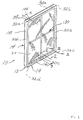
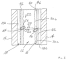
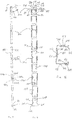
- FIG. 1 An insulating glass unit 10 constructed according to the present invention is illustrated by Figures 1-3 as comprising a spacer assembly 12 sandwiched between glass sheets, or lights, 14.
- the assembly 12 comprises a frame structure 16, sealant material 18 for hermetically joining the frame to the lights to form a closed space 20 within the unit 10 and a body 22 of desiccant in the space 20.
- the unit 10 is illustrated as in condition for final assembly into a window or door frame, not illustrated, for ultimate installation in a building.
- the glass lights 14 are constructed from any suitable or conventional glass.
- the lights are rectangular, aligned with each other and sized so that their peripheries are disposed just outwardly of the frame outer periphery. While it is not essential that the lights be transparent, the disclosure and description which follows assumes the unit 10 is used in a window frame installed in a building.
- the assembly 12 functions to maintain the lights 14 spaced apart from each other to produce the hermetic insulating "dead air space" 20 between them.
- the frame 16 and the sealant body 18 coact to provide a structure which maintains the lights 14 properly assembled with the space 20 sealed from atmospheric moisture over long time periods during which the unit 10 is subjected to frequent significant thermal stresses.
- the desiccant body 22 serves to remove water vapor from air, or other gas, entrapped in the space 20 during construction of the unit 10.
- the sealant body 18 both structurally adheres the lights 14 to the spacer assembly 12 and hermetically closes the space 20 against infiltration of airborne water vapor from the atmosphere surrounding the unit 10.
- the illustrated body 18 is formed from a "hot melt” material which is attached to the frame sides and outer periphery to form a U-shaped cross section.
- the sealant body 18 is extruded onto the frame 16. This is accomplished for example by passing the frame through a sealant application station of an extruder such as that disclosed by U.S. Patent 4,628,582.
- a "hot melt” sealant is disclosed, other suitable or conventional substances (singly or in combination) for sealing and structurally securing the unit components together may be employed.
- the sealant body 18 After the sealant body 18 is attached to the frame 16 it is heated and the lights 14 and spacer assembly 12 are passed through the nips of a series of press rolls (not illustrated). The rolls compress the body 18 between the frame 16 and the lights 14 to adhere them firmly together.
- the hot melt forming the body 18 is a composition which assures strong adhesion to the frame and the lights by joints which are both structurally strong and impervious to atmospheric moisture infiltration of the space 20.
- the "bight" 18a of the U-shaped sealant body ( Figure 2) is continuous with the legs 18b and functions to lengthen the vapor barrier between the glass and the body while encapsulating the frame exterior.
- the frame 16 extends about the unit periphery to provide a structurally strong, stable spacer for maintaining the lights aligned and spaced while minimizing heat conduction between the lights via the frame.
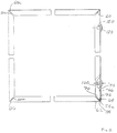
- the preferred frame 16 comprises a plurality of spacer frame segments, or members, 30a-d (see Figures 5-7) connected to form a planar, polygonal frame shape, element juncture forming frame corner structures 32a-d, and connecting structure 34 for joining opposite frame element ends to complete the closed frame shape.
- Each frame member 30 is elongated and has a channel shaped cross section defining a peripheral wall 40 and first and second lateral walls 42, 44. See Figure 2.
- the peripheral wall 40 extends continuously about the unit 10 except where the connecting structure 34 joins the frame member ends.
- the lateral walls 42, 44 are integral with respective opposite peripheral wall sides.
- the lateral walls extend inwardly from the peripheral wall 40 in a direction parallel to the planes of the lights and the frame.
- the preferred frame 16 has stiffening flanges 46 formed along the inwardly projecting lateral wall edges.
- the lateral walls 42, 44 rigidify the frame member 30 so it resists flexure and bending in a direction transverse to its longitudinal extent.
- the flanges 46 stiffen the walls 42, 44 so they resist bending and flexure transverse to their longitudinal extents.
- the frame 16 is preferably constructed from a thin ribbon of stainless steel material (e.g. 304 stainless steel having a thickness of 0.006-0.010 inches) which is passed through forming rolls to produce the walls 40, 42, 44.
- the formed ribbon (see Figures 6 and 7) is an elongated linear rigid channel member.
- the desiccant body 22 is attached to the frame wall 40 and disposed on each of the frame members 30a-d.
- the desiccant body 22 is formed by a desiccated matrix in which a particulate desiccant is incorporated in a vehicle material which is adhered to the frame.
- the vehicle material may be silicone, hot melt, polyurethane, or other suitable materials.
- the desiccant absorbs moisture from the surrounding atmosphere for a time after the desiccant is exposed to the atmosphere.
- the desiccant absorbs moisture from the atmosphere within the space 20 for some time after the unit 10 has been fabricated. This assures that condensation within the unit does not occur.
- the desiccant body 22 is extruded onto the frame 16 by an extruder.
- the frame corner structures 32 facilitate manual frame bending to the final, polygonal frame configuration in the unit 10 while assuring an effective vapor seal at the frame corners.
- the frame 16 is initially formed in a single straight length with the sealant body 18 in place on the straight frame.
- the corner structures 32 initially comprise notches 50 and weakened zones 52 formed in the walls 42, 44 at frame corner locations. See Figures 6 and 7.
- the notches 50 extend into the walls 42, 44 from the respective lateral wall edges.
- the lateral walls 42, 44 extend continuously along the frame 16 from one end to the other.
- the walls 42, 44 are weakened at the corner locations because the notches reduce the amount of lateral wall material and eliminate the stiffening flanges 46.
- the weak zones 52 at each corner act to restrict frame bending to a crease line 54 extending across the wall 40 at that corner and to form a pleat 56, or sealant pocket, at the corner.
- the weak zones 52 are formed by a series of five score lines radiating across the lateral walls 42, 44 from the corner crease line location.
- the weak zones are bowed inwardly from the plane of their associated lateral walls.
- the sealant body 18 adheres and conforms to the inwardly bowed weak zones.
- Each pleat 56 forms a pocket-like conical, or pyramid shaped, channel 58 filled with sealant having its apex adjacent the corner crease line 54 and its base opening within the frame channel (see Figures 2 and 3).
- the weak zones 52 are specially formed so that the frame corners are well defined, without use of tools or fixtures, simply by manually bending the frame into its final configuration.
- the controlled corner formation is assured in the preferred frame by score lines 60a, 60b extending normal to each other and at 45° angles from the plane of the wall 40.
- the lines 60a, 60b define mitre-like creases in the lateral walls which confront each other when the frame corner forms a 90°angle.
- the weak zones 52 are unsymmetrically formed about the centerline of the frame wall 40. Thus when the frame corners are bent the weak zones collapse inwardly to form the pleats without clashing. This is particularly important in constructing relatively narrow spacer assemblies (e.g. where the wall 40 is only about 3/8 inch wide).
- the score lines 60c-e are formed to assure this non clashing relationship.
- the line 60c bisects the angle between the lines 60a, 60b to define the inwardly projecting limit of pleat extension.
- the lines 60d, 60e respectively bisect the angle between the lines 60a, 60c and 60b, 60c.
- the score lines 60d in the frame wall 42 all weaken the wall more than the score lines 60e in the wall 42.
- the score lines 60e in the wall 44 all weaken the wall 44 more than do the score lines 60d.
- the weak zones are deformed, or dished, inwardly before the sealant is applied with the inward deformation being nonsymmetrical due to differential weakening.
- This differential weakening of the weak zones 52 is illustrated in an exaggerated way in Figure 6. When the frame is bent to its final configuration the weakened zones collapse inwardly along nonintersecting skew lines so clashing is avoided.
- the sealant is applied to the lateral walls 42, 44 at the corner locations before the frame is bent so the sealant adheres to the inwardly dished weak zone walls. Some of this sealant at the frame corners is entrapped within the pleats 56 after the frame is bent. This sealant fills the pleats to assure the conical channel 58 blocks vapor infiltration at the frame corner. Some sealant may well out of the pleats between the adjacent score lines 60 to the external lateral sides of each frame corner as the frame is bent. This is beneficial because adequate corner sealant is assured.
- the connecting structure 34 secures the opposite frame ends 62, 64 together when the frame has been bent to its final configuration.
- the illustrated connecting structure comprises a connecting tongue structure 66 continuous with and projecting from the frame structure end 62 and a tongue receiving structure 70 at the other frame end 64.
- the preferred tongue and tongue receiving structures 66, 70 are constructed and sized relative to each other to form a telescopic joint 72. When assembled, the telescopic joint 72 maintains the frame in its final polygonal configuration prior to assembly of the unit 10.
- the tongue 66 is formed as a frame corner extension and comprises a tongue body 74 and tongue stiffening walls 76, 78.
- the tongue body 74 is formed an extension of the frame wall 40 and joins the wall 40 at a corner bend line 54a.
- a corner structure 32a is formed at the junctures of the tongue walls 76, 78 and the respective lateral walls 42, 44.
- the frame is bent at the corners 32 into its final planar rectangular shape.
- the tongue 66 is bent about the corner bend line 54a for telescoping engagement with the tongue receiving frame end 64.
- the corner structure 32a defines tongue pleats 80 (similar to the pleats 56) respectively joining the frame walls 42, 44 with the respective tongue walls 76, 78.
- the preferred tongue body 74 is narrower than the wall 40 so that it can be inserted within the tongue receiving frame member end 64 to complete the telescopic joint 72.
- the tongue 66 is abruptly narrowed at the location where the tongue pleats 80 join the respective sidewalls 42, 44.
- the junctures of the tongue pleats and frame sidewalls each form a mitre-like angled step, or shoulder, 84.
- the tongue body 74 is just enough narrower than the frame wall 40 that the tongue walls 76, 78 frictionally engage the respective receiving frame member walls 42, 44. Maintenance of the frictional fit between the tongue walls 76, 78 and the lateral frame walls 42, 44 is assured by a resiliently deflectable crown 81 extending along the longitudinal centerline of the tongue body 74. The crown is deflected somewhat as the tongue is inserted into the frame end 64 to provide a resilient spring-like effect urging the walls 76, 78 into engagement with the frame walls 42, 44.
- the tongue body 74 and tongue walls 76, 78 are subjected to a swedging operation after the frame members are substantially fully formed.
- the swedging operation narrows the tongue body by forcing some of the tongue body material into the tongue walls, thus reducing the tongue width.
- the swedging operation may also produce the crown 81.
- the frame end 64 is formed so the walls 42, 44 terminate in a mitre cut edge 82 which, when the telescopic joint 72 is properly formed, confronts and extends immediately adjacent the shoulder 84.
- the shoulder 84 forms a stop for the edge 82 when the joint is fully assembled.
- the edge 82 is aligned with the shoulder 84 so that the exterior laterally facing frame surfaces at the corner structure 32a are in common planes.
- the frame end 64 is constructed to provide a keeper structure for engaging the tongue wall edges 92, 94 when the telescopic joint is completed.
- the preferred keeper structure is formed by the lateral wall flanges 46 which serve to maintain the tongue 66 within the frame end 64, but other keeper structures, such as corrugations formed in the lateral frame walls 42, 44, could be employed if desired.
- the connector structure 34 further comprises a fastener arrangement 100 for both connecting the opposite frame ends together and providing a temporary vent for the space 20 while the unit 10 is being fabricated.
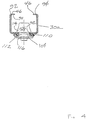
- the illustrated fastener arrangement (see Figures 1, 4, 5 and 6) is formed by conforming holes 102, 104 located, respectively, in the tongue 66 and the frame end 64 and a rivet 106 extending through the holes 102, 104 for clinching the tongue 66 and frame end 64 together.
- the holes 102, 104 readily communicate the air space 20 in the unit 10 to the ambient atmosphere when the unit 10 is first assembled before the rivet 106 is installed.
- the holes are aligned when the tongue and tongue receiving structure are telescoped together.
- the sealant body 18 at the location of the frame hole 104 defines an opening surrounding the hole.
- the desiccant body 22 does not obstruct the hole 104 because the desiccant body 22 is not applied to the frame end 64 in the vicinity of the hole 104.
- the tongue hole 102 is also clear of sealant and the desiccant body because they are not applied to the tongue 66.
- the holes 102, 104 communicate the space 20 to the surroundings and the space 20 remains at atmospheric pressure. This is to be distinguished from units which, after they are assembled and cooled down, exhibit inward light diaphragming which must be relieved by piercing the unit sealant.
- the rivet 106 is installed after the unit 10 has been heated, pressed and cooled to about room temperature.
- the space 20 is flooded with an inert gas (such as Argon) just before the rivet is placed.
- the rivet 106 is a "blind" rivet carrying a resilient sealing ring 110 about its central hollow shaft 112.
- the rivet head 116 forces the sealing ring 110 into tightly compressed sealing engagement with the frame wall 40 surrounding the hole 104. No further communication through the holes is possible so the inert gas is trapped in the space 20.
- additional sealant is gunned or trowelled (or otherwise applied) onto the unit 10 to cover the rivet and the corner structure 32a where the opposite ends of the sealant body 18 meet.
- the material at the juncture of the sealant body ends is smoothed over to assure an effective vapor barrier at the corner 32a.
- the drawings shows such a unit. See Figures 1, 5 and 6.
- the second vent 120 is formed by a punched hole in the frame wall 40 spaced along the common frame member from the hole 104.
- the sealant body 18 and the desiccant body 22 each define an opening surrounding the vent 120 so that air venting from the space 20 is not impeded.
- the second vent 120 is closed by a blind rivet 122 identical to the rivet 106.
- the rivets 106, 122 are installed at the same time and each is covered with sealant material so that the seal provided by each rivet is augmented by the sealant material.
- the unit 10 is illustrated as constructed to simulate the appearance of a multipane window. This is accomplished by the inclusion of a mounting bar simulating assembly 130 in the unit ( Figure 1).
- the mounting bar simulating assembly 130 is referred to here as a mounting bar assembly for simplicity, but it is not a true mounting bar assembly because the individual mounting bars do not connect with panes or lights in the windows.
- the mounting bar assembly 130 comprises bar members 132 extending across the space 20 between the lights 14, and clips 134 for connecting the bars 132 to the spacer assembly 12.
- the bars 132 are formed by elongated metal tubes having generally rectangular cross sectional shapes. Each illustrated bar 132 extends between the mid-points of its associated frame members through the center of the space 20.
- the bars 132 are provided with dados at their intersection.
- the clips 134 detachably secure the bars to the spacer frame 16.
- Each clip comprises a body 136, a bar support 138 projecting in one direction from the body, and latches 140, 142 projecting in the opposite direction from the body.
- the preferred clip 134 latches into small rectangular notches 144 ( Figure 6) formed in the associated frame wall stiffening flanges 46 with the clip body extending adjacent the flanges 46.
- the notches 144 are relatively shallow and do not extend the full depth of the stiffening flanges 46. Accordingly the frame members are not materially weakened at the notch locations since the flanges 46 remain substantially intact and effective to strengthen the frame member.
- the body 136 is a flat rectangular or square plate-like member having opposite margins 136a, 136b seated on the frame wall stiffening flanges 46.
- the latches 140, 142 project from the body between the flanges 46 into the channel formed by the frame member while the bar support 138 projects into the space 20.
- the bar support 138 comprises a base flange 150 integral with the body 136, a central spine 152 projecting from the base flange, and bar retaining fingers 154 which fit into the mounting bar interior.
- Each latch 140, 142 comprises a relatively rigid latch body member 156 projecting from the clip body and a thin latching finger 158 extending from the projecting end of the latch body back toward the adjacent clip body margin.
- Each latching finger is resiliently deflectable toward and away from the latch body.
- the latching body and finger are formed with a wedge face 160 on one side which facilitates inserting the clip into the receiving flange notch 144.
- the finger 158 is resiliently deflected by the flange notch edge as the clip is inserted into the frame member. When the finger 158 clears the notch edge the finger snaps back to its undeflected position and traps the flange 46 between the finger 158 and the clip body 136.
- an insulating glass unit constructed according to the present invention might employ a sealant body formed from multiple hot melt seals, multiple polyisobutylene seals, or from a single polyurethane or polysulfide seal.
- sealant bodies might be supplemented with still a further layer of sealant material extending about their peripheries.
Landscapes
- Engineering & Computer Science (AREA)
- Civil Engineering (AREA)
- Structural Engineering (AREA)
- Securing Of Glass Panes Or The Like (AREA)
- Gas-Filled Discharge Tubes (AREA)
- Manufacture Of Switches (AREA)
- Electronic Switches (AREA)
- Laminated Bodies (AREA)
- Wing Frames And Configurations (AREA)
Applications Claiming Priority (3)
| Application Number | Priority Date | Filing Date | Title |
|---|---|---|---|
| US827281 | 1992-01-29 | ||
| US07/827,281 US5313761A (en) | 1992-01-29 | 1992-01-29 | Insulating glass unit |
| EP93100393A EP0553642B1 (fr) | 1992-01-29 | 1993-01-13 | Vitrage isolant |
Related Parent Applications (1)
| Application Number | Title | Priority Date | Filing Date |
|---|---|---|---|
| EP93100393.3 Division | 1993-01-13 |
Publications (2)
| Publication Number | Publication Date |
|---|---|
| EP0688934A2 true EP0688934A2 (fr) | 1995-12-27 |
| EP0688934A3 EP0688934A3 (fr) | 1996-06-05 |
Family
ID=25248799
Family Applications (2)
| Application Number | Title | Priority Date | Filing Date |
|---|---|---|---|
| EP95113318A Withdrawn EP0688934A3 (fr) | 1992-01-29 | 1993-01-13 | Vitrage isolant |
| EP93100393A Expired - Lifetime EP0553642B1 (fr) | 1992-01-29 | 1993-01-13 | Vitrage isolant |
Family Applications After (1)
| Application Number | Title | Priority Date | Filing Date |
|---|---|---|---|
| EP93100393A Expired - Lifetime EP0553642B1 (fr) | 1992-01-29 | 1993-01-13 | Vitrage isolant |
Country Status (5)
| Country | Link |
|---|---|
| US (2) | US5313761A (fr) |
| EP (2) | EP0688934A3 (fr) |
| AT (1) | ATE152805T1 (fr) |
| CA (1) | CA2087937C (fr) |
| DE (1) | DE69310392T2 (fr) |
Cited By (6)
| Publication number | Priority date | Publication date | Assignee | Title |
|---|---|---|---|---|
| DE102004020883A1 (de) * | 2004-04-26 | 2005-11-10 | Karl Lenhardt | Isolierglasscheibe und Verfahren zu ihrer Herstellung |
| EP2626496A1 (fr) * | 2012-02-10 | 2013-08-14 | Technoform Glass Insulation Holding GmbH | Profil d'espaceur pour cadre d'espaceur pour une unité de verre isolant avec éléments d'intervalle et unité de verre isolant |
| CN104153687A (zh) * | 2014-08-29 | 2014-11-19 | 大连华工创新科技股份有限公司 | 一种中空玻璃 |
| CN104196421A (zh) * | 2014-08-29 | 2014-12-10 | 大连华工创新科技股份有限公司 | 一种中空玻璃 |
| CN105696917A (zh) * | 2016-03-17 | 2016-06-22 | 大连华工创新科技股份有限公司 | 一种中空玻璃隔热条及中空玻璃 |
| US10132114B2 (en) | 2011-01-25 | 2018-11-20 | Technoform Glass Insulation Holding Gmbh | Spacer profile and insulating glass unit comprising such a spacer |
Families Citing this family (140)
| Publication number | Priority date | Publication date | Assignee | Title |
|---|---|---|---|---|
| US5675944A (en) * | 1990-09-04 | 1997-10-14 | P.P.G. Industries, Inc. | Low thermal conducting spacer assembly for an insulating glazing unit and method of making same |
| US5255481A (en) * | 1990-09-04 | 1993-10-26 | Ppg Industries, Inc. | Spacer and spacer frame for an insulating glazing unit and method of making same |
| US5531047A (en) * | 1993-08-05 | 1996-07-02 | Ppg Industries, Inc. | Glazing unit having three or more glass sheets and having a low thermal edge, and method of making same |
| US5797436A (en) * | 1995-06-26 | 1998-08-25 | Oden Corporation | Liquid filling machine technical field |
| US5678376A (en) * | 1995-10-30 | 1997-10-21 | Poma; James P. | Universal intercept clip |
| US6038825A (en) * | 1996-02-21 | 2000-03-21 | The Lockformer Company | Insulated glass window spacer and method for making window spacer |
| US5851609A (en) | 1996-02-27 | 1998-12-22 | Truseal Technologies, Inc. | Preformed flexible laminate |
| US6180708B1 (en) | 1996-06-28 | 2001-01-30 | W. R. Grace & Co.-Conn. | Thermoplastic adsorbent compositions containing wax and insulating glass units containing such compositions |
| US5813191A (en) * | 1996-08-29 | 1998-09-29 | Ppg Industries, Inc. | Spacer frame for an insulating unit having strengthened sidewalls to resist torsional twist |
| MXPA99005203A (es) | 1996-12-05 | 2006-07-18 | Sashlite Llc | Unidad de ventana con cristales multiples integrados y montaje de marco y metodo para fabricarlo. |
| US6286288B1 (en) * | 1996-12-05 | 2001-09-11 | Vertical Ventures V-5, Llc | Integrated multipane window unit and sash assembly and method for manufacturing the same |
| DE69736356T2 (de) | 1996-12-05 | 2007-08-02 | Sashlite, LLC, Westport | Integrierte mehrfachverglaste fenstereinheit und -flügel |
| US6708384B2 (en) | 1997-02-07 | 2004-03-23 | Glass Equipment Development, Inc. | Notched muntin bars having two finishes |
| US6687982B2 (en) * | 2001-02-12 | 2004-02-10 | Glass Equipment Development, Inc. | Laminated muntin bar apparatus |
| US6355317B1 (en) | 1997-06-19 | 2002-03-12 | H. B. Fuller Licensing & Financing, Inc. | Thermoplastic moisture cure polyurethanes |
| US5899033A (en) * | 1998-01-30 | 1999-05-04 | Lake Country Sales, Inc. | Adjustable hub assembly for window muntins |
| US6115989A (en) * | 1998-01-30 | 2000-09-12 | Ppg Industries Ohio, Inc. | Multi-sheet glazing unit and method of making same |
| US6289641B1 (en) | 1998-01-30 | 2001-09-18 | Ppg Industries Ohio, Inc. | Glazing unit having three or more spaced sheets and a single spacer frame and method of making same |
| JP2002501999A (ja) | 1998-01-30 | 2002-01-22 | ピーピージー・インダストリーズ・オハイオ・インコーポレイテッド | 多層シートガラスユニットおよびその形成方法 |
| US6250026B1 (en) | 1998-01-30 | 2001-06-26 | Ppg Industries Ohio, Inc. | Multi-sheet glazing unit having a single spacer frame and method of making same |
| US5950398A (en) * | 1998-10-22 | 1999-09-14 | Hubbard; Bruce M. | Pass-by insulating glass window unit and method for replacing single glazing |
| US6131356A (en) * | 1999-01-14 | 2000-10-17 | Gieseke; Gerald G. | Muntin bar clip |
| US6244012B1 (en) | 1999-01-20 | 2001-06-12 | Glass Equipment Development, Inc. | Muntin grid and joiner |
| US6336984B1 (en) | 1999-09-24 | 2002-01-08 | Guardian Industries Corporation | Vacuum IG window unit with peripheral seal at least partially diffused at temper |
| US6365242B1 (en) | 1999-07-07 | 2002-04-02 | Guardian Industries Corp. | Peripheral seal for vacuum IG window unit |
| US6558494B1 (en) | 1999-09-24 | 2003-05-06 | Guardian Industries Corp. | Vacuum IG window unit with edge seal at least partially diffused at temper and completed via microwave curing, and corresponding method of making the same |
| US6311455B1 (en) * | 1999-10-01 | 2001-11-06 | Odl, Incorporated | Insulated glass spacer with integral muntin |
| US6301843B1 (en) | 2000-04-04 | 2001-10-16 | Silver Line Building Products Corp. | Muntin joint |
| AU2001253668A1 (en) * | 2000-04-19 | 2001-11-07 | Ashland Products, Inc. | Balance system for sash window assembly |
| US6701749B2 (en) | 2000-09-27 | 2004-03-09 | Guardian Industries Corp. | Vacuum IG window unit with edge seal at least partially diffused at temper and completed via microwave curing, and corresponding method of making the same |
| US6494002B1 (en) | 2000-10-19 | 2002-12-17 | Gerald G. Gieseke | Muntin bar clip with spikes |
| DE20018012U1 (de) * | 2000-10-20 | 2002-03-07 | R & R Sondermaschinen GmbH, 90579 Langenzenn | Endstopfen zum Anschrauben von Sprossen an Abstandhalterrahmen von insbesondere Isolierglasscheiben |
| US6739101B2 (en) * | 2001-01-19 | 2004-05-25 | Cardinal Ig Company | Methods and apparatus for manufacturing muntin bar assemblies |
| US6662523B2 (en) | 2001-06-15 | 2003-12-16 | Sashlite, Llc | Insulating glass sash assemblies with adhesive mounting and spacing structures |
| MXPA03011621A (es) * | 2001-06-15 | 2004-06-30 | Sashlite Llc | Bastidor de ventana de multihoja de vidrio integrada y metodo para fabricar el bastidor de ventana de multihoja de vidrio integrado. |
| US6916392B2 (en) | 2001-06-21 | 2005-07-12 | Cardinal Ig Company | Producing and servicing insulating glass units |
| US7200211B1 (en) | 2004-10-12 | 2007-04-03 | Palmsource, Inc. | Method and system for providing information for identifying callers based on a partial number |
| US6546692B1 (en) | 2001-10-03 | 2003-04-15 | Film Technologies International, Inc. | Method of mounting an insulated impact resistant glass composite in a window frame |
| US6804924B2 (en) * | 2001-10-12 | 2004-10-19 | Cardinal Ig Company | Repair of insulating glass units |
| US6868884B2 (en) * | 2001-11-01 | 2005-03-22 | Ged Integrated Solutions, Inc. | Method and apparatus for applying optical film to glass |
| US20030084622A1 (en) * | 2001-11-05 | 2003-05-08 | Sashlite, Llc | Components for multipane window unit sash assemblies |
| US6679013B2 (en) | 2001-11-15 | 2004-01-20 | Sashlite, Llc | Window assembly with hinged components |
| US7043881B2 (en) * | 2002-06-14 | 2006-05-16 | Tem-Pace, Inc. | Insulated glass assembly with an internal lighting system |
| US6926782B2 (en) * | 2002-06-27 | 2005-08-09 | Glass Equipment Development, Inc. | Method and apparatus for processing sealant of an insulating glass unit |
| US20040074588A1 (en) * | 2002-10-21 | 2004-04-22 | Sashlite, Llc | Assembly of insulating glass structures on an integrated sash |
| AU2003284097A1 (en) * | 2002-10-22 | 2004-05-13 | Sashlite, Llc | Grid muntin retaining clips for muntins |
| US7001464B1 (en) * | 2003-03-05 | 2006-02-21 | Erdman Automation Corporation | System and process for glazing glass to windows and door frames |
| US7082727B2 (en) * | 2003-05-16 | 2006-08-01 | Industries Covers Inc. | Hung window with snap-fit assembly |
| US7021110B2 (en) * | 2003-05-23 | 2006-04-04 | Ppg Industries Ohio, Inc. | Apparatus for preparing U-shaped spacers for insulating units |
| US7270859B2 (en) * | 2003-05-28 | 2007-09-18 | H.B. Fuller Licensing & Financing Inc. | Insulating glass assembly including a polymeric spacing structure |
| US7132059B2 (en) * | 2003-05-29 | 2006-11-07 | H.B. Fuller Licensing & Financing, Inc. | Ambient applied desiccant matrix composition |
| US7588653B2 (en) * | 2003-06-23 | 2009-09-15 | Ppg Industries Ohio, Inc. | Method of making an integrated window sash |
| US7950194B2 (en) | 2003-06-23 | 2011-05-31 | Ppg Industries Ohio, Inc. | Plastic spacer stock, plastic spacer frame and multi-sheet unit, and method of making same |
| WO2005001229A2 (fr) * | 2003-06-23 | 2005-01-06 | Ppg Industries Ohio, Inc. | Chassis de fenetre integre et son procede de production |
| US7827761B2 (en) | 2003-06-23 | 2010-11-09 | Ppg Industries Ohio, Inc. | Plastic spacer stock, plastic spacer frame and multi-sheet unit, and method of making same |
| US7856791B2 (en) * | 2003-06-23 | 2010-12-28 | Ppg Industries Ohio, Inc. | Plastic spacer stock, plastic spacer frame and multi-sheet unit, and method of making same |
| US7739851B2 (en) * | 2003-06-23 | 2010-06-22 | Ppg Industries Ohio, Inc. | Plastic spacer stock, plastic spacer frame and multi-sheet unit, and method of making same |
| US20050086880A1 (en) * | 2003-10-27 | 2005-04-28 | Polowinczak Allen D. | Muntin clip |
| US7124546B2 (en) * | 2003-11-18 | 2006-10-24 | Pella Corporation | Muntin bar connector with positioning tabs |
| US20050136198A1 (en) * | 2003-11-18 | 2005-06-23 | Panelite, L.L.C. | Insulating glass units with inserts and method of producing same |
| US7063757B2 (en) * | 2004-01-08 | 2006-06-20 | Ged Integrated Solutions, Inc. | Method and apparatus for applying optical film to glass |
| DE202004004734U1 (de) * | 2004-03-24 | 2005-09-08 | Kronenberg, Max | Mehrteiliger Steckverbinder |
| US7694469B2 (en) * | 2004-07-01 | 2010-04-13 | Newell Operating Company | Muntin grid |
| CA2512762A1 (fr) * | 2004-07-21 | 2006-01-21 | Newell Operating Company | Pince de petit bois |
| US20080295451A1 (en) * | 2004-08-04 | 2008-12-04 | Erwin Brunnhofer | Blank for Spacer for Insulating Window Unit, Spacer for Insulating Window Unit, Insulating Window Unit and Method For Manufacturing a Spacer |
| US7105068B2 (en) * | 2004-08-20 | 2006-09-12 | Ged Integrated Solutions, Inc. | Method and apparatus for applying aligned tape patterns |
| US20060037689A1 (en) * | 2004-08-20 | 2006-02-23 | Glass Equipment Development, Inc. | Method and apparatus for applying ductile tape |
| US7195824B2 (en) * | 2004-08-20 | 2007-03-27 | Ged Integrated Solutions, Inc. | Decorative tape |
| DE202005019973U1 (de) * | 2004-09-09 | 2006-04-06 | Technoform Caprano Und Brunnhofer Gmbh & Co. Kg | Abstandshalterprofil für einen Abstandshalterrahmen für eine Isolierscheibeneinheit und Isolierscheibeneinheit |
| US7866033B2 (en) * | 2004-09-29 | 2011-01-11 | Ged Integrated Solutions, Inc. | Window component system including pusher for scrap removal |
| US7802365B2 (en) * | 2004-09-29 | 2010-09-28 | Ged Integrated Solutions, Inc. | Window component scrap reduction |
| US7610681B2 (en) * | 2004-09-29 | 2009-11-03 | Ged Integrated Solutions, Inc. | Window component stock indexing |
| US7445682B2 (en) | 2004-09-29 | 2008-11-04 | Ged Intergrated Solution, Inc. | Window component stock transferring |
| ES2587655T3 (es) * | 2004-11-03 | 2016-10-26 | Quanex Ig Systems, Inc. | Pinza de barras de celosía de ventana y método para usar la misma |
| US7694470B2 (en) | 2004-12-10 | 2010-04-13 | Newell Operating Company | Muntin clip |
| US7685782B2 (en) * | 2004-12-10 | 2010-03-30 | Newell Operating Company | Muntin clip |
| US8376019B2 (en) | 2005-01-11 | 2013-02-19 | Pella Corporation | Window assembly with movable interior sash |
| CA2842274C (fr) * | 2005-02-10 | 2017-03-07 | Ged Integrated Solutions, Inc. | Clip souple |
| US20070000195A1 (en) * | 2005-05-03 | 2007-01-04 | Christian Garces | Decorative lattice structure and methods for manufacturing and installing same |
| US7779583B2 (en) * | 2005-12-09 | 2010-08-24 | Newell Operating Company | Muntin clip |
| US20070157544A1 (en) * | 2005-12-15 | 2007-07-12 | Benjamin Zurn | Novel muntin bar assemblies |
| US20070193188A1 (en) * | 2006-01-06 | 2007-08-23 | Newell Operating Company | Muntin Clip |
| US20070169427A1 (en) * | 2006-01-24 | 2007-07-26 | Lee David E Iii | Decorative grid system and method |
| US20080060290A1 (en) * | 2006-07-24 | 2008-03-13 | Ged Integrated Solutions, Inc. | Thermally Efficient Window Frame |
| US8001742B2 (en) * | 2006-08-16 | 2011-08-23 | Ged Integrated Solutions, Inc. | Muntin bar clip and muntin bar assembly |
| GB0616582D0 (en) * | 2006-08-21 | 2006-09-27 | Honey Ian | Frame assembly for sheet material |
| US7681369B2 (en) * | 2006-08-22 | 2010-03-23 | Soltesiz Joseph R | Double pane window construction |
| US20080127581A1 (en) * | 2006-08-31 | 2008-06-05 | Nick Walters | Security window insert assembly |
| US20080066411A1 (en) * | 2006-09-18 | 2008-03-20 | Newell Operating Company | Muntin Bar Joiner |
| US8104238B2 (en) * | 2006-11-17 | 2012-01-31 | Formtek Metal Forming, Inc. | Window spacer and corner-fastening concept |
| DE202007016649U1 (de) * | 2007-04-02 | 2008-04-30 | Technoform Caprano Und Brunnhofer Gmbh & Co. Kg | Leiterförmiger Isoliersteg für ein Verbundprofil für Fenster-, Türen- und Fassadenelemente und Verbundprofil für Fenster-, Türen- und Fassadenelemente |
| US7748185B2 (en) | 2007-08-30 | 2010-07-06 | Ppg Industries Ohio, Inc. | Muntin grids for transparencies and transparencies having muntin grids |
| US7954284B2 (en) * | 2007-08-30 | 2011-06-07 | Ppg Industries Ohio, Inc. | Retainer clip for grid simulating muntins |
| US8481634B2 (en) | 2007-09-07 | 2013-07-09 | Bostik, Inc. | Hot melt desiccant matrix composition based on plasticized polyolefin binder |
| KR100958845B1 (ko) * | 2007-11-06 | 2010-05-19 | 주식회사 서울레이저발형시스템 | 금속판재의 절곡장치 |
| US20090139164A1 (en) * | 2007-12-04 | 2009-06-04 | Intigral, Inc. | Insulating glass unit |
| US20090139163A1 (en) * | 2007-12-04 | 2009-06-04 | Intigral, Inc. | Insulating glass unit |
| US20090139165A1 (en) * | 2007-12-04 | 2009-06-04 | Intigral, Inc. | Insulating glass unit |
| DE102008054799A1 (de) * | 2008-12-17 | 2010-06-24 | Hilti Aktiengesellschaft | Ankerschiene |
| DE102008054807A1 (de) * | 2008-12-17 | 2010-06-24 | Hilti Aktiengesellschaft | Ankerschiene |
| US7762466B2 (en) * | 2008-12-18 | 2010-07-27 | Symbol Technologies, Inc. | Two position zoom lens assembly for an imaging-based bar code reader |
| US8726487B2 (en) | 2009-05-12 | 2014-05-20 | Ged Integrated Solutions, Inc. | Efficient assembly of double or triple pane windows |
| US8813337B2 (en) | 2009-05-12 | 2014-08-26 | Ged Integrated Solutions, Inc. | Efficient assembly of insulating glass windows |
| US10303035B2 (en) | 2009-12-22 | 2019-05-28 | View, Inc. | Self-contained EC IGU |
| US11314139B2 (en) | 2009-12-22 | 2022-04-26 | View, Inc. | Self-contained EC IGU |
| US9958750B2 (en) | 2010-11-08 | 2018-05-01 | View, Inc. | Electrochromic window fabrication methods |
| US10180606B2 (en) | 2010-12-08 | 2019-01-15 | View, Inc. | Connectors for smart windows |
| US9442339B2 (en) | 2010-12-08 | 2016-09-13 | View, Inc. | Spacers and connectors for insulated glass units |
| CN112731720A (zh) | 2010-12-08 | 2021-04-30 | 唯景公司 | 绝缘玻璃装置的改良隔板 |
| US8643933B2 (en) | 2011-12-14 | 2014-02-04 | View, Inc. | Connectors for smart windows |
| US20120174523A1 (en) * | 2011-01-07 | 2012-07-12 | Zeeuw Michael W | Continuous metal building framing member |
| US9454055B2 (en) | 2011-03-16 | 2016-09-27 | View, Inc. | Multipurpose controller for multistate windows |
| US10175549B2 (en) | 2011-03-16 | 2019-01-08 | View, Inc. | Connectors for smart windows |
| US9352512B2 (en) | 2011-04-13 | 2016-05-31 | Ged Integrated Solutions, Inc. | Flexible film heated roller |
| US9389025B2 (en) * | 2011-06-08 | 2016-07-12 | Ail Research Inc. | Heat and mass exchangers having extruded plates |
| US11719039B2 (en) | 2011-12-14 | 2023-08-08 | View, Inc. | Connectors for smart windows |
| CN102606032B (zh) * | 2012-03-09 | 2014-07-16 | 段军会 | 具有三联式推拉门上门框的推拉门 |
| CN102619442A (zh) * | 2012-04-19 | 2012-08-01 | 上海索尔装饰成套制品有限公司 | 玻璃安装连接结构 |
| US8915032B1 (en) * | 2012-05-04 | 2014-12-23 | Angelo Rivera | Frameless impact window system |
| US11255120B2 (en) | 2012-05-25 | 2022-02-22 | View, Inc. | Tester and electrical connectors for insulated glass units |
| EP2888427B1 (fr) | 2012-08-23 | 2021-02-17 | View, Inc. | Dispositifs électrochromiques (ec) alimentés par une énergie photonique |
| KR101665898B1 (ko) | 2012-09-05 | 2016-10-12 | 피피지 인더스트리즈 오하이오 인코포레이티드 | 태양광 모듈 프레임 |
| US9359808B2 (en) | 2012-09-21 | 2016-06-07 | Ppg Industries Ohio, Inc. | Triple-glazed insulating unit with improved edge insulation |
| EP2984052B1 (fr) * | 2013-04-11 | 2018-12-26 | View, Inc. | Procédés de fabrication d'un vitrage isolé compensé en pression |
| CA2850875A1 (fr) * | 2013-05-30 | 2014-11-30 | Benjamin J. Zurn | Vitrage isolant rempli de gaz adsorbable |
| US10012019B2 (en) | 2013-12-31 | 2018-07-03 | Guardian Glass, LLC | Vacuum insulating glass (VIG) unit with metallic peripheral edge seal and/or methods of making the same |
| US9784027B2 (en) | 2013-12-31 | 2017-10-10 | Guardian Glass, LLC | Vacuum insulating glass (VIG) unit with metallic peripheral edge seal and/or methods of making the same |
| US10280680B2 (en) | 2013-12-31 | 2019-05-07 | Guardian Glass, LLC | Vacuum insulating glass (VIG) unit with pump-out port sealed using metal solder seal, and/or method of making the same |
| US9428953B2 (en) | 2014-06-12 | 2016-08-30 | Ged Integrated Solutions, Inc. | Spacer frame and method of making same |
| WO2016100075A1 (fr) | 2014-12-15 | 2016-06-23 | View, Inc. | Joints pour fenêtres électrochromiques |
| US20160258205A1 (en) * | 2015-03-03 | 2016-09-08 | Andersen Corporation | Offset seam for insulating glass unit spacer and method of using and manufacturing the same |
| USD1058859S1 (en) | 2015-05-04 | 2025-01-21 | Ged Integrated Solutions, Inc. | Spacer frame |
| US10145005B2 (en) | 2015-08-19 | 2018-12-04 | Guardian Glass, LLC | Techniques for low temperature direct graphene growth on glass |
| CA3025670C (fr) * | 2016-06-03 | 2023-07-04 | Tomm Tech Pty Ltd | Systemes et elements de panneau |
| WO2018017688A1 (fr) * | 2016-07-19 | 2018-01-25 | Newtonoid Technologies L.L.C. | Système de fenêtre avec insert pour prévenir les bris de verre |
| US10900274B2 (en) * | 2016-09-02 | 2021-01-26 | Pella Corporation | Anti-rattle elements for internal divider of glass assembly |
| US10267083B2 (en) | 2016-09-30 | 2019-04-23 | Ged Integrated Solutions, Inc. | Tactile spacer frame assembly and locking member |
| US11585148B2 (en) | 2019-02-08 | 2023-02-21 | Ged Integrated Solutions, Inc. | Muntin assembly and method of manufacture |
| WO2022040298A1 (fr) * | 2020-08-18 | 2022-02-24 | Ged Integrated Solutions, Inc. | Cadre d'espacement amélioré avec élément de verrouillage montant |
| US12538989B2 (en) * | 2020-11-12 | 2026-02-03 | Hussmann Corporation | Transparent door |
Citations (1)
| Publication number | Priority date | Publication date | Assignee | Title |
|---|---|---|---|---|
| US4628582A (en) | 1981-12-04 | 1986-12-16 | Glass Equipment Development, Inc. | Method of making spacer frame for an insulating glass panel |
Family Cites Families (59)
| Publication number | Priority date | Publication date | Assignee | Title |
|---|---|---|---|---|
| GB349875A (en) * | 1930-09-18 | 1931-06-04 | Ejnar Alexander Roon Byskou | Improvements in glazed frames or sashes |
| US1877336A (en) * | 1930-12-18 | 1932-09-13 | Lovell George | Panel for the walls and doors of refrigerators and cold storage rooms |
| US1975895A (en) * | 1933-06-19 | 1934-10-09 | Gen Motors Corp | Sealed double-pane glass and frame |
| US2173664A (en) * | 1936-03-23 | 1939-09-19 | Gen Motors Corp | Double windowpane construction |
| US2235680A (en) * | 1937-07-14 | 1941-03-18 | Libbey Owens Ford Glass Co | Multiple glass sheet glazing unit and method of making the same |
| US2348307A (en) * | 1942-12-03 | 1944-05-09 | Gen Motors Corp | Double windowpane |
| US2625717A (en) * | 1945-06-12 | 1953-01-20 | Libbey Owens Ford Glass Co | Multiple sheet glazing unit |
| US2587063A (en) * | 1949-03-26 | 1952-02-26 | Harold W Petsch | Multiple glazing unit |
| US2768475A (en) * | 1952-11-28 | 1956-10-30 | Rca Corp | Method of making glass-to-metal seal |
| US2750637A (en) * | 1952-11-28 | 1956-06-19 | Libbey Owens Ford Glass Co | Multiple sheet glazing units |
| US2869694A (en) * | 1954-07-23 | 1959-01-20 | Air Filter Corp | Frame construction for filter units |
| US3045297A (en) * | 1956-07-31 | 1962-07-24 | Ljungdahl Erland Samuel | Multiple pane window unit |
| US3021243A (en) * | 1956-08-27 | 1962-02-13 | Jean Pierre De Montmolin | Method of producing a durable mechanical bond between glass and another material |
| DE1082386B (de) * | 1957-08-22 | 1960-05-25 | Thermo Chemical Dev Company | Mehrscheibenisolierglas |
| US2996161A (en) * | 1957-10-28 | 1961-08-15 | Weather Seal Inc | Metal door frame construction |
| US3030673A (en) * | 1957-12-26 | 1962-04-24 | Harry J London | Multiple glass sheet glazing unit |
| US3026582A (en) * | 1959-02-04 | 1962-03-27 | Bayer Franz Xaver | Composite glass sheet |
| US3105274A (en) * | 1961-05-19 | 1963-10-01 | Armstrong Patents Co Ltd | Multiple glass pane glazing unit and method of fabrication |
| DE1229272B (de) * | 1963-03-12 | 1966-11-24 | Libbey Owens Ges Fuer Maschine | Mehrscheiben-Isolierglas |
| US3212179A (en) * | 1963-03-18 | 1965-10-19 | Koblensky Joseph Paul | Process for manufacturing a glazing unit |
| US3280523A (en) * | 1964-01-08 | 1966-10-25 | Pittsburgh Plate Glass Co | Multiple glazing unit |
| US3283890A (en) * | 1964-06-22 | 1966-11-08 | United Shoe Machinery Corp | Thermoplastic adhesive rods or strips |
| US3657900A (en) * | 1969-08-01 | 1972-04-25 | Ppg Industries Inc | Packaging arrangement for a multiple glazed unit spacer assembly |
| US3686814A (en) * | 1970-02-02 | 1972-08-29 | Anderson Mfg Co V E | False window muntin bar structure |
| US3919023A (en) * | 1973-09-24 | 1975-11-11 | Ppg Industries Inc | Multiple glazed unit |
| DE2404396A1 (de) * | 1974-01-30 | 1975-08-07 | Greschbach Stahlbau | Schliesschlitzabdeckung fuer stahlzargen |
| US4109431A (en) * | 1974-03-25 | 1978-08-29 | Ppg Industries, Inc. | Sealing and spacing unit for multiple glazed windows |
| DE2506298A1 (de) * | 1975-02-14 | 1976-08-19 | Juergen Von Der Ley | Aus vorgefertigten teilen zusammengesetztes wandelement |
| US3974823A (en) * | 1975-02-18 | 1976-08-17 | Ppg Industries, Inc. | Solar collector having minimum edge heat loss |
| US4063002A (en) * | 1975-04-14 | 1977-12-13 | Wilson Jr Floyd | Insulated glass and sealant therefor |
| GB1509178A (en) * | 1975-05-13 | 1978-04-26 | Percy Lane Ltd | Double glazed windows |
| US4015394A (en) * | 1975-10-14 | 1977-04-05 | Gerald Kessler | Double-insulated glass window with insulating spacer |
| DE2637034C2 (de) * | 1976-08-17 | 1982-06-03 | Helmut Lingemann GmbH & Co, 5600 Wuppertal | Abstandhalterrahmen für Isolierverglasungen |
| US4057945A (en) * | 1976-10-19 | 1977-11-15 | Gerald Kessler | Insulating spacer for double insulated glass |
| US4084720A (en) * | 1977-01-24 | 1978-04-18 | Frost Packaging Company | Box construction |
| CA1134125A (fr) * | 1978-06-14 | 1982-10-26 | Theo Janssens | Panneaux creux, et dispositif et methode de fabrication connexes |
| US4222213A (en) * | 1978-11-14 | 1980-09-16 | Gerald Kessler | Insulating spacer for double insulated glass |
| US4431691A (en) * | 1979-01-29 | 1984-02-14 | Tremco, Incorporated | Dimensionally stable sealant and spacer strip and composite structures comprising the same |
| FR2449222A1 (fr) * | 1979-02-15 | 1980-09-12 | Kaeuferle Stahlbau J | Perfectionnements aux procedes et dispositifs de fabrication de plaques composites, notamment de glaces doubles |
| DK154715C (da) * | 1980-02-20 | 1989-05-16 | Teijin Ltd | Vindueskonstruktion |
| US4513546A (en) * | 1980-03-12 | 1985-04-30 | Norton Company | Corner key for window spacer element |
| US4530195A (en) * | 1980-04-03 | 1985-07-23 | Glass Equipment Development, Inc. | Spacer frame for an insulating glass panel and method of making the same |
| DE3325718A1 (de) * | 1983-07-16 | 1985-01-31 | Helmut Lingemann GmbH & Co, 5600 Wuppertal | Gebogene ecke eines abstandhalterrahmens einer isolierverglasung sowie verfahren zu ihrer herstellung |
| US4546723A (en) * | 1984-04-19 | 1985-10-15 | Glass Equipment Development, Inc. | Method and apparatus for applying sealant to insulating glass panel spacer frames |
| US4622249A (en) * | 1985-04-15 | 1986-11-11 | Ppg Industries, Inc. | Multiple pane unit having a flexible spacing and sealing assembly |
| CA1285177C (fr) * | 1986-09-22 | 1991-06-25 | Michael Glover | Element vitre a panneaux scelles multiples |
| US4808452A (en) * | 1986-11-14 | 1989-02-28 | Products Research & Chemical Corp. | Multi-pane thermally insulating construction |
| US4780164A (en) * | 1986-11-20 | 1988-10-25 | Cardinal Ig Company | Method for producing gas-containing insulating glass assemblies |
| US4807419A (en) * | 1987-03-25 | 1989-02-28 | Ppg Industries, Inc. | Multiple pane unit having a flexible spacing and sealing assembly |
| NO162126C (no) * | 1987-08-24 | 1989-11-08 | Spilka Inco Ltd As | Anordning ved metallramme og fremgangsmaate til fremstilling av samme. |
| US4783938A (en) * | 1988-02-05 | 1988-11-15 | Sne Enterprises | Window panel assembly |
| DE8805653U1 (de) * | 1988-04-28 | 1988-06-30 | Cera Handelsgesellschaft Mbh, 8954 Biessenhofen | Sprossenverbinder für einen aus einem Hohlprofil bestehenden Isolierglasscheiben-Abstandhalterrahmen |
| US4873803A (en) * | 1988-06-13 | 1989-10-17 | The B.F. Goodrich Company | Insulating a window pane |
| US4856243A (en) * | 1988-07-25 | 1989-08-15 | Owens-Corning Fiberglas Corporation | Assemblies for windows and doors |
| US4970840A (en) * | 1989-07-21 | 1990-11-20 | Raymond Ouellette | Window assembly and grille |
| US4989384A (en) * | 1990-01-02 | 1991-02-05 | Rolscreen Company | Insulated window assembly with internal muntin bars |
| CA2125504C (fr) * | 1990-09-04 | 1996-12-10 | Robert B. Hodek | Entretoise de faible conductivite thermique pour vitrage isolant et mode de fabrication connexe |
| US5177916A (en) * | 1990-09-04 | 1993-01-12 | Ppg Industries, Inc. | Spacer and spacer frame for an insulating glazing unit and method of making same |
| US5099626A (en) * | 1990-11-14 | 1992-03-31 | Allmetal Inc. | Connection for tubular muntin bars |
-
1992
- 1992-01-29 US US07/827,281 patent/US5313761A/en not_active Expired - Lifetime
-
1993
- 1993-01-13 EP EP95113318A patent/EP0688934A3/fr not_active Withdrawn
- 1993-01-13 DE DE69310392T patent/DE69310392T2/de not_active Expired - Lifetime
- 1993-01-13 EP EP93100393A patent/EP0553642B1/fr not_active Expired - Lifetime
- 1993-01-13 AT AT93100393T patent/ATE152805T1/de not_active IP Right Cessation
- 1993-01-22 CA CA002087937A patent/CA2087937C/fr not_active Expired - Lifetime
-
1994
- 1994-02-15 US US08/196,699 patent/US5678377A/en not_active Expired - Lifetime
Patent Citations (1)
| Publication number | Priority date | Publication date | Assignee | Title |
|---|---|---|---|---|
| US4628582A (en) | 1981-12-04 | 1986-12-16 | Glass Equipment Development, Inc. | Method of making spacer frame for an insulating glass panel |
Cited By (14)
| Publication number | Priority date | Publication date | Assignee | Title |
|---|---|---|---|---|
| DE102004020883A1 (de) * | 2004-04-26 | 2005-11-10 | Karl Lenhardt | Isolierglasscheibe und Verfahren zu ihrer Herstellung |
| US10132114B2 (en) | 2011-01-25 | 2018-11-20 | Technoform Glass Insulation Holding Gmbh | Spacer profile and insulating glass unit comprising such a spacer |
| AU2013218322B2 (en) * | 2012-02-10 | 2016-12-08 | Pellini S.P.A. | Spacer profile for a spacer frame for an insulating glass unit with interspace elements and insulating glass unit |
| CN104185714A (zh) * | 2012-02-10 | 2014-12-03 | 泰诺风玻璃隔热控股股份有限公司 | 用于具有间隙元件的中空玻璃单元的间隔框架的间隔型材和中空玻璃单元 |
| JP2015512844A (ja) * | 2012-02-10 | 2015-04-30 | テクノフォーム グラス インシュレーション ホールディング ゲーエムベーハー | 合間要素を有する断熱ガラスユニット用のスペーサー・フレームのためのスペーサー・プロフィールおよび断熱ガラスユニット |
| CN104185714B (zh) * | 2012-02-10 | 2016-05-18 | 泰诺风玻璃隔热控股股份有限公司 | 用于具有间隙元件的中空玻璃单元的间隔框架的间隔型材和中空玻璃单元 |
| WO2013117320A1 (fr) | 2012-02-10 | 2013-08-15 | Technoform Glass Insulation Holding Gmbh | Profilé d'espacement pour un cadre d'espacement pour un vitrage isolant à éléments de distance, et vitrage isolant |
| RU2607545C2 (ru) * | 2012-02-10 | 2017-01-10 | Текноформ Гласс Инсулейшн Холдинг Гмбх | Дистанционный профиль для дистанционной рамки стеклопакета с внутрипакетными элементами и стеклопакет |
| US9810016B2 (en) | 2012-02-10 | 2017-11-07 | Technoform Glass Insulation Holding Gmbh | Spacer profile for a spacer frame for an insulating glass unit with interspace elements and insulating glass unit |
| EP2626496A1 (fr) * | 2012-02-10 | 2013-08-14 | Technoform Glass Insulation Holding GmbH | Profil d'espaceur pour cadre d'espaceur pour une unité de verre isolant avec éléments d'intervalle et unité de verre isolant |
| CN104153687A (zh) * | 2014-08-29 | 2014-11-19 | 大连华工创新科技股份有限公司 | 一种中空玻璃 |
| CN104196421A (zh) * | 2014-08-29 | 2014-12-10 | 大连华工创新科技股份有限公司 | 一种中空玻璃 |
| CN105696917A (zh) * | 2016-03-17 | 2016-06-22 | 大连华工创新科技股份有限公司 | 一种中空玻璃隔热条及中空玻璃 |
| CN105696917B (zh) * | 2016-03-17 | 2018-07-31 | 大连华工创新科技股份有限公司 | 一种中空玻璃隔热条及中空玻璃 |
Also Published As
| Publication number | Publication date |
|---|---|
| EP0688934A3 (fr) | 1996-06-05 |
| US5313761A (en) | 1994-05-24 |
| EP0553642A2 (fr) | 1993-08-04 |
| EP0553642A3 (en) | 1993-10-13 |
| EP0553642B1 (fr) | 1997-05-07 |
| CA2087937C (fr) | 1996-12-17 |
| DE69310392D1 (de) | 1997-06-12 |
| US5678377A (en) | 1997-10-21 |
| ATE152805T1 (de) | 1997-05-15 |
| DE69310392T2 (de) | 1997-10-23 |
| CA2087937A1 (fr) | 1993-07-30 |
Similar Documents
| Publication | Publication Date | Title |
|---|---|---|
| EP0553642B1 (fr) | Vitrage isolant | |
| US5048997A (en) | Flexible cornerpiece for spacer frame for insulated glass panel | |
| US5813191A (en) | Spacer frame for an insulating unit having strengthened sidewalls to resist torsional twist | |
| US6823643B2 (en) | Integrated multipane window unit and sash assembly and method for manufacturing the same | |
| US6928776B2 (en) | Window sash frame with hinged components | |
| US4149348A (en) | Multiple glazed unit having inner sheet mounted within a spacer | |
| US4499703A (en) | Method of retro-fitting windows | |
| US20060218875A1 (en) | Components for multipane window unit sash assemblies | |
| EP1050657A2 (fr) | Vitrage multiple et châssis de fenêtre intégré et son procédé de fabrication | |
| US3389522A (en) | Glass unit and method | |
| JPH02217549A (ja) | 押出しモジュラーパネルユニット | |
| MXPA97006462A (es) | Bastidor espaciador para unidad aislante con paredes laterales reforzadas para resistir el alabeo torsional | |
| EP3679216B1 (fr) | Cadre de fenêtre à haut rendement thermique | |
| US20220127900A1 (en) | Spacer frame joiner clip and method of use | |
| US20080127581A1 (en) | Security window insert assembly | |
| US4183693A (en) | Corner piece for a double glazed window construction | |
| CA2187826C (fr) | Vitrage isolant | |
| WO1983002973A1 (fr) | Chassis d'entretoisement pour un panneau de verre isolant | |
| US20040194413A1 (en) | Muntins | |
| KR101887580B1 (ko) | 범용의 조립성으로 개선된 창호 시스템 | |
| CA1290195C (fr) | Garniture isolante ajustable pour fenetre | |
| JPH04119092U (ja) | 障子等のサツシのガラスパネル組付け体 | |
| CN120513339A (zh) | 双层玻璃制造方法及由此制造的双层玻璃窗户系统 | |
| JPH046480U (fr) | ||
| CA2015645A1 (fr) | Systeme de bati de fenetre extrude |
Legal Events
| Date | Code | Title | Description |
|---|---|---|---|
| PUAI | Public reference made under article 153(3) epc to a published international application that has entered the european phase |
Free format text: ORIGINAL CODE: 0009012 |
|
| 17P | Request for examination filed |
Effective date: 19950824 |
|
| AC | Divisional application: reference to earlier application |
Ref document number: 553642 Country of ref document: EP |
|
| AK | Designated contracting states |
Kind code of ref document: A2 Designated state(s): AT BE CH DE DK FR GB IE IT LI LU MC NL PT SE |
|
| PUAL | Search report despatched |
Free format text: ORIGINAL CODE: 0009013 |
|
| AK | Designated contracting states |
Kind code of ref document: A3 Designated state(s): AT BE CH DE DK FR GB IE IT LI LU MC NL PT SE |
|
| 17Q | First examination report despatched |
Effective date: 19981214 |
|
| STAA | Information on the status of an ep patent application or granted ep patent |
Free format text: STATUS: THE APPLICATION IS DEEMED TO BE WITHDRAWN |
|
| 18D | Application deemed to be withdrawn |
Effective date: 19990427 |