EP0689116A2 - Verfahren und Vorrichtung zur Schätzung des Gefälle- und Seitenneigungswinkels einer Fahrbahn - Google Patents
Verfahren und Vorrichtung zur Schätzung des Gefälle- und Seitenneigungswinkels einer Fahrbahn Download PDFInfo
- Publication number
- EP0689116A2 EP0689116A2 EP95201476A EP95201476A EP0689116A2 EP 0689116 A2 EP0689116 A2 EP 0689116A2 EP 95201476 A EP95201476 A EP 95201476A EP 95201476 A EP95201476 A EP 95201476A EP 0689116 A2 EP0689116 A2 EP 0689116A2
- Authority
- EP
- European Patent Office
- Prior art keywords
- angle
- road surface
- vehicle
- estimating
- accordance
- Prior art date
- Legal status (The legal status is an assumption and is not a legal conclusion. Google has not performed a legal analysis and makes no representation as to the accuracy of the status listed.)
- Granted
Links
- 238000000034 method Methods 0.000 title claims abstract description 17
- 230000001133 acceleration Effects 0.000 claims description 71
- 230000006870 function Effects 0.000 claims description 27
- NCGICGYLBXGBGN-UHFFFAOYSA-N 3-morpholin-4-yl-1-oxa-3-azonia-2-azanidacyclopent-3-en-5-imine;hydrochloride Chemical compound Cl.[N-]1OC(=N)C=[N+]1N1CCOCC1 NCGICGYLBXGBGN-UHFFFAOYSA-N 0.000 claims description 6
- 230000002401 inhibitory effect Effects 0.000 claims description 5
- 238000010586 diagram Methods 0.000 description 4
- 239000000725 suspension Substances 0.000 description 3
- 230000001052 transient effect Effects 0.000 description 2
- 230000005540 biological transmission Effects 0.000 description 1
Images



Classifications
-
- G—PHYSICS
- G01—MEASURING; TESTING
- G01C—MEASURING DISTANCES, LEVELS OR BEARINGS; SURVEYING; NAVIGATION; GYROSCOPIC INSTRUMENTS; PHOTOGRAMMETRY OR VIDEOGRAMMETRY
- G01C9/00—Measuring inclination, e.g. by clinometers, by levels
-
- B—PERFORMING OPERATIONS; TRANSPORTING
- B60—VEHICLES IN GENERAL
- B60G—VEHICLE SUSPENSION ARRANGEMENTS
- B60G17/00—Resilient suspensions having means for adjusting the spring or vibration-damper characteristics, for regulating the distance between a supporting surface and a sprung part of vehicle or for locking suspension during use to meet varying vehicular or surface conditions, e.g. due to speed or load
- B60G17/015—Resilient suspensions having means for adjusting the spring or vibration-damper characteristics, for regulating the distance between a supporting surface and a sprung part of vehicle or for locking suspension during use to meet varying vehicular or surface conditions, e.g. due to speed or load the regulating means comprising electric or electronic elements
- B60G17/019—Resilient suspensions having means for adjusting the spring or vibration-damper characteristics, for regulating the distance between a supporting surface and a sprung part of vehicle or for locking suspension during use to meet varying vehicular or surface conditions, e.g. due to speed or load the regulating means comprising electric or electronic elements characterised by the type of sensor or the arrangement thereof
-
- B—PERFORMING OPERATIONS; TRANSPORTING
- B60—VEHICLES IN GENERAL
- B60T—VEHICLE BRAKE CONTROL SYSTEMS OR PARTS THEREOF; BRAKE CONTROL SYSTEMS OR PARTS THEREOF, IN GENERAL; ARRANGEMENT OF BRAKING ELEMENTS ON VEHICLES IN GENERAL; PORTABLE DEVICES FOR PREVENTING UNWANTED MOVEMENT OF VEHICLES; VEHICLE MODIFICATIONS TO FACILITATE COOLING OF BRAKES
- B60T8/00—Arrangements for adjusting wheel-braking force to meet varying vehicular or ground-surface conditions, e.g. limiting or varying distribution of braking force
- B60T8/17—Using electrical or electronic regulation means to control braking
- B60T8/172—Determining control parameters used in the regulation, e.g. by calculations involving measured or detected parameters
-
- B—PERFORMING OPERATIONS; TRANSPORTING
- B60—VEHICLES IN GENERAL
- B60G—VEHICLE SUSPENSION ARRANGEMENTS
- B60G2400/00—Indexing codes relating to detected, measured or calculated conditions or factors
- B60G2400/05—Attitude
- B60G2400/052—Angular rate
- B60G2400/0523—Yaw rate
-
- B—PERFORMING OPERATIONS; TRANSPORTING
- B60—VEHICLES IN GENERAL
- B60G—VEHICLE SUSPENSION ARRANGEMENTS
- B60G2400/00—Indexing codes relating to detected, measured or calculated conditions or factors
- B60G2400/10—Acceleration; Deceleration
- B60G2400/106—Acceleration; Deceleration longitudinal with regard to vehicle, e.g. braking
-
- B—PERFORMING OPERATIONS; TRANSPORTING
- B60—VEHICLES IN GENERAL
- B60G—VEHICLE SUSPENSION ARRANGEMENTS
- B60G2400/00—Indexing codes relating to detected, measured or calculated conditions or factors
- B60G2400/80—Exterior conditions
- B60G2400/82—Ground surface
-
- B—PERFORMING OPERATIONS; TRANSPORTING
- B60—VEHICLES IN GENERAL
- B60G—VEHICLE SUSPENSION ARRANGEMENTS
- B60G2800/00—Indexing codes relating to the type of movement or to the condition of the vehicle and to the end result to be achieved by the control action
- B60G2800/01—Attitude or posture control
- B60G2800/019—Inclination due to load distribution or road gradient
-
- B—PERFORMING OPERATIONS; TRANSPORTING
- B60—VEHICLES IN GENERAL
- B60G—VEHICLE SUSPENSION ARRANGEMENTS
- B60G2800/00—Indexing codes relating to the type of movement or to the condition of the vehicle and to the end result to be achieved by the control action
- B60G2800/01—Attitude or posture control
- B60G2800/019—Inclination due to load distribution or road gradient
- B60G2800/0192—Inclination due to load distribution or road gradient longitudinal with regard to vehicle
-
- B—PERFORMING OPERATIONS; TRANSPORTING
- B60—VEHICLES IN GENERAL
- B60G—VEHICLE SUSPENSION ARRANGEMENTS
- B60G2800/00—Indexing codes relating to the type of movement or to the condition of the vehicle and to the end result to be achieved by the control action
- B60G2800/01—Attitude or posture control
- B60G2800/019—Inclination due to load distribution or road gradient
- B60G2800/0194—Inclination due to load distribution or road gradient transversal with regard to vehicle
-
- B—PERFORMING OPERATIONS; TRANSPORTING
- B60—VEHICLES IN GENERAL
- B60T—VEHICLE BRAKE CONTROL SYSTEMS OR PARTS THEREOF; BRAKE CONTROL SYSTEMS OR PARTS THEREOF, IN GENERAL; ARRANGEMENT OF BRAKING ELEMENTS ON VEHICLES IN GENERAL; PORTABLE DEVICES FOR PREVENTING UNWANTED MOVEMENT OF VEHICLES; VEHICLE MODIFICATIONS TO FACILITATE COOLING OF BRAKES
- B60T2210/00—Detection or estimation of road or environment conditions; Detection or estimation of road shapes
- B60T2210/20—Road shapes
- B60T2210/22—Banked curves
-
- B—PERFORMING OPERATIONS; TRANSPORTING
- B60—VEHICLES IN GENERAL
- B60W—CONJOINT CONTROL OF VEHICLE SUB-UNITS OF DIFFERENT TYPE OR DIFFERENT FUNCTION; CONTROL SYSTEMS SPECIALLY ADAPTED FOR HYBRID VEHICLES; ROAD VEHICLE DRIVE CONTROL SYSTEMS FOR PURPOSES NOT RELATED TO THE CONTROL OF A PARTICULAR SUB-UNIT
- B60W2520/00—Input parameters relating to overall vehicle dynamics
- B60W2520/14—Yaw
-
- B—PERFORMING OPERATIONS; TRANSPORTING
- B60—VEHICLES IN GENERAL
- B60W—CONJOINT CONTROL OF VEHICLE SUB-UNITS OF DIFFERENT TYPE OR DIFFERENT FUNCTION; CONTROL SYSTEMS SPECIALLY ADAPTED FOR HYBRID VEHICLES; ROAD VEHICLE DRIVE CONTROL SYSTEMS FOR PURPOSES NOT RELATED TO THE CONTROL OF A PARTICULAR SUB-UNIT
- B60W2552/00—Input parameters relating to infrastructure
- B60W2552/15—Road slope, i.e. the inclination of a road segment in the longitudinal direction
Definitions
- the present invention relates to a method and apparatus for estimating the incline and bank angles of a road surface upon which a vehicle is travelling.
- Sophisticated vehicular control systems may desire to alter various operational attributes such as suspension, transmission shifting and anti-lock braking characteristics in the presence of varying driving conditions.
- various operational attributes such as suspension, transmission shifting and anti-lock braking characteristics in the presence of varying driving conditions.
- Incline and bank angles of a road surface upon which the vehicle is travelling represent two such conditions.
- the present invention is directed to a method and apparatus for estimating incline and bank angles of a road surface upon which a front wheel drive vehicle is travelling.
- each nondriven rear wheel is equipped with a rotational speed sensor.
- the vehicle is further equipped with longitudinal and lateral accelerometers mounted to the vehicle chassis above the centerline of the rear axle. Outputs from the speed sensors and accelerometers are fed into a vehicle on-board controller and utilized by the controller in computing the incline and bank angles of the road surface.
- Incline and bank angle methods and apparatuses are defined by the features specified in Claims 1, 6, 11 and 15.
- the present invention provides for estimation of the incline angle of a road surface by (i) computing a longitudinal acceleration as a function of the rotational speeds of the vehicle's rear wheels sensed by the speed sensors, (ii) determining a pitch angle of the vehicle as a function of the longitudinal acceleration sensed by the longitudinal accelerometer, and (iii) computing an estimated incline angle of the road surface as a function of the computed longitudinal acceleration, sensed longitudinal acceleration and the pitch angle.
- An embodiment may provide for determining a yaw rate of the vehicle as a function of the difference between the sensed rotational speeds of the rear wheels, and the distance between them. Incline angle estimation can, therefore, be inhibited if a change in yaw rate is greater than a predetermined threshold, indicative of angular acceleration.
- the present invention also provides for estimation of the bank angle of a road surface by (i) computing a longitudinal velocity as an average of the rotational speeds of the vehicle's rear wheels sensed by the speed sensors, (ii) determining a roll angle of the vehicle as a function of the lateral acceleration sensed by the longitudinal accelerometer, (iii) determining a yaw rate of the vehicle as a function of the difference between the sensed rotational speeds of the rear wheels, and the distance between them, and (iv) computing an estimated bank angle of the road surface as a function of the computed longitudinal velocity, the sensed lateral acceleration, the roll angle and the yaw rate.
- An embodiment may provide for inhibiting bank angle estimation if a change in yaw rate is greater than a predetermined threshold, indicative of angular acceleration.
- Updated incline and bank angles are maintained in the controller's memory for access by various control systems to alter vehicle attributes for improved handling and operation.
- FIG. 1 is a schematic illustration of a vehicle equipped with the apparatus of the present invention.
- vehicle 10 includes front-driven steering wheels 12 and 14, nondriven nonsteering rear wheels 16 and 18, controller 26, speed sensors 22 and 24, and lateral and longitudinal accelerometers 32 and 34, respectively.
- Speed sensors 22 and 24 are responsive to the rotational speed of rear wheels 16 and 18, respectively. Outputs of the speed sensors 22 and 24 are fed into controller 26 via signal lines 28 and 30, respectively.
- Lateral accelerometer 32 is mounted to the vehicle chassis 10 above the centerline of the rear axle 36 and is responsive to vehicular acceleration normal to the longitudinal centerline 20 of the vehicle.
- the output of the lateral accelerometer 32 is fed into controller 26 via signal line 38.
- Longitudinal accelerometer 34 is mounted to the vehicle chassis 10 above the centerline of the rear axle 36 and is responsive to vehicular acceleration parallel to the longitudinal centerline 20 of the vehicle. The output of the longitudinal accelerometer 34 is fed into controller 26 via signal line 40.
- the controller 26 utilizes inputs received from the speed sensors 22 and 24 and accelerometers 32 and 34 to compute the incline and bank angles of the road surface in accordance with computer routines contained within the controller 26.
- Updated incline and bank angles are maintained in memory within the controller 26 for access by various vehicle control systems to alter vehicle attributes for improved handling and operation.
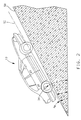
- FIG. 2 is a schematic illustration of a vehicle 10 travelling up an inclined road surface 50 having an angle of incline ⁇ I .
- the analysis and result are identical for a vehicle travelling down the same inclined road surface 50.
- the total angle of incline ⁇ T of the vehicle 10 is equal to the incline angle ⁇ I of the road surface 50 plus the pitch angle ⁇ P of the vehicle 10.
- PITCH STIFFNESS is a constant term particular to a specific vehicle design.
- g is an abbreviated form for earth's gravitational force at one atmosphere and is often used as a unit for acceleration.
- SENSED LONGITUDINAL ACCELERATION represents the longitudinal acceleration, in units of g, as sensed by the longitudinal accelerometer 34.
- the output of an accelerometer is a voltage signal having a magnitude varying in accordance with varying acceleration.
- the controller 26 of FIG. 1 compares the voltage level of the longitudinal accelerometer 34 with a predetermined voltage level corresponding to an acceleration equal to g. In this way, the controller 26 arrives at an acceleration in units of g corresponding to the actual accelerometer voltage output.
- an accelerometer output voltage level of 2 volts may correspond to an acceleration of 1 g. So an accelerometer with an output of 1 volt corresponds to an acceleration of 0.5 g, or 4.9 m/s2.
- SENSED LONGITUDINAL ACCELERATION (YAW RATE X LATERAL VELOCITY) + COMPUTED LONGITUDINAL ACCELERATION + G[SIN ( ⁇ I + ⁇ P )] + BIAS LONG YAW RATE is the rate of vehicle turning in degrees per second. It is computed as follows: For a forward travelling vehicle, a positive yaw rate represents a clockwise vehicle turning maneuver, while a negative yaw rate represents a counterclockwise vehicle turning maneuver.
- LATERAL VELOCITY is the speed by which the vehicle is travelling laterally. It exists during transient conditions such as varying yaw rates or angular accelerations. However, incline angle computation is not performed during varying yaw rates to insure computational accuracy. Therefore, LATERAL VELOCITY is essentially zero and the first term of equation (2) is negligible.
- Each of the two rear wheels 16 and 18 have rotational speed sensors 22 and 24, respectively.
- the output of the two sensors are utilized by the controller 26 to compute the average speed of the two rear wheels, thereby achieving a longitudinal velocity.
- Longitudinal velocity is recalculated each scan of the controller 26.
- the change in longitudinal velocity from one scan to the next is divided by the scan rate of the controller to arrive at the COMPUTED LONGITUDINAL ACCELERATION term of equation (2).
- BIAS LONG is a known constant voltage offset corresponding to the amount of offset of the longitudinal accelerometer 34 from a perpendicular to the vehicle plane 52.
- An accelerometer which is offset will result in a constant voltage bias which must be accounted for in computing acceleration.
- ⁇ I SIN ⁇ 1 [SENSED LONGITUDINAL ACCELERATION - COMPUTED LONGITUDINAL ACCELERATION - BIAS LONG ] - ⁇ P Since all quantities in equation (4) are known, the incline angle ⁇ I of the road surface 50 can be computed.
- FIG. 3 is a flow diagram for an incline angle calculation routine contained within and performed by controller 26 for implementation of the present invention. The routine is performed each scan of the controller. Referring to FIG. 3, step 60, input signals from the two rear wheel speed sensors 22 and 24 and the longitudinal accelerometer 34 are read via signal lines 28, 30 and 40, respectively.
- the vehicle yaw rate is computed in accordance with equation (3) based upon the newly read inputs of step 60.
- the newly computed yaw rate of step 62 is compared in step 64 with the previously calculated yaw rate of step 62 stored in memory during the last scan of the controller 26. If the difference between the two yaw rates is greater than a predetermined threshold, the controller 26 exits the routine. This ensures that the incline angle computation is not performed during angular accelerations which could affect the accuracy of the computation.
- the newly computed yaw rate of step 62 is stored into memory at step 70 for reference during the next scan of the controller 26.
- the controller 26 computes a longitudinal velocity in accordance with the average rear wheel speeds.
- a vehicle longitudinal acceleration is computed as a change in the longitudinal velocity of step 66 from the previously computed longitudinal velocity of step 66 stored in memory during the last scan of the controller 26, divided by the scan rate of the controller 26.
- the controller 26 identifies the vehicle longitudinal acceleration sensed by the longitudinal accelerometer 34 corresponding to the input read in step 60.
- the vehicle pitch stiffness is multiplied by the sensed longitudinal acceleration of step 72 to arrive at a vehicle pitch angle ⁇ P .
- the incline angle ⁇ I of the road surface 50 is computed in accordance with equation (4), and filtered by methods well known to those skilled in the art to eliminate noise.
- the incline angle ⁇ I is then stored in memory at step 78 for use by various vehicle control systems to improve handling and operation.
- the computed yaw rate of step 62 and longitudinal velocity of step 66 are stored in memory in step 70 for reference during the next scan of the controller 26.
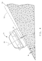
- FIG. 4 is a schematic illustration of a vehicle 10 travelling along a banked road surface 50 having an angle of bank ⁇ B .
- the total angle of bank ⁇ T of the vehicle 10 is equal to the bank angle ⁇ B of the road surface 50 plus the roll angle ⁇ R of the vehicle 10.
- ROLL STIFFNESS is a constant term particular to a specific vehicle design. It is a function of such design parameters as vehicle size, weight distribution, wheel base and suspension.
- g is an abbreviated form for earth's gravitational force at one atmosphere and is often used as a unit for acceleration.
- SENSED LATERAL ACCELERATION represents the lateral acceleration, in units of g, as sensed by the lateral accelerometer 32.
- a roll angle ⁇ R in degrees is obtained.
- SENSED LATERAL ACCELERATION (YAW RATE X COMPUTED LONGITUDINAL VELOCITY) + D(LATERAL VELOCITY)/DT + G[SIN( ⁇ S + ⁇ P )] + BIAS LAT YAW RATE is the rate of vehicle turning in degrees per second. It is computed as follows: Each of the two rear wheels 16 and 18 have rotational speed sensors 22 and 24, respectively. The output of the two sensors are utilized by the controller 26 to compute the average speed of the two rear wheels, thereby achieving a longitudinal velocity. Longitudinal velocity is recalculated each scan of the controller 26.
- LATERAL VELOCITY is the speed by which the vehicle is travelling laterally. It exists during transient conditions such as varying yaw rates or angular accelerations. However, incline angle computation is not performed during varying yaw rates to insure computational accuracy. Therefore, D(LATERAL VELOCITY)DT is essentially zero and the second term of equation (6) is negligible.
- BIAS LAT is a known constant voltage offset corresponding to the degree of offset of the lateral accelerometer 32 from a perpendicular to the vehicle plane 52.
- An accelerometer which is offset will result in a constant voltage bias which must be accounted for in computing acceleration.
- ⁇ B SIN ⁇ 1[SENSED LATERAL ACCELERATION - (YAW RATE X COMPUTED LONGITUDINAL VELOCITY) - BIAS LAT ] - ⁇ R Since all quantities in equation (8) are known, the bank angle ⁇ B of the road surface 50 can be computed.
- FIG. 5 is a flow diagram for a bank angle calculation routine contained within and performed by controller 26 for implementation of the present invention. The routine is performed each scan of the controller. Referring to FIG. 5, step 80, input signals from the two rear wheel speed sensors 22 and 24 and the lateral accelerometer 32 are read via signal lines 28, 30 and 38, respectively.
- the vehicle yaw rate is computed in accordance with equation (7) based upon the newly read inputs of step 80.
- the newly computed yaw rate of step 82 is compared in step 84 with the previously calculated yaw rate of step 82 stored in memory during the last scan of the controller 26. If the difference between the two yaw rates is greater than a predetermined threshold, the controller 26 exits the routine. This ensures that the bank angle computation is not performed during angular accelerations which could affect the accuracy of the computation.
- the newly computed yaw rate of step 82 is stored into memory at step 88 for reference during the next scan of the controller 26.
- the controller 26 computes a vehicle longitudinal velocity in accordance with the average wheel speeds.
- the controller 26 identifies the vehicle lateral acceleration sensed by the lateral accelerometer 32 corresponding to the input read in step 80.
- the vehicle roll stiffness is multiplied by the sensed lateral acceleration of step 92 to arrive at a vehicle roll angle ⁇ R .
- the bank angle ⁇ B of the road surface 50 is computed in accordance with equation (8), and filtered to eliminate noise.
- the bank angle ⁇ B is then stored in memory at step 98 for use by various vehicle control systems to improve handling and operation.
- the computed yaw rate of step 82 and longitudinal velocity of step 86 are stored in memory in step 90 for reference during the next scan of the controller 26.
Landscapes
- Engineering & Computer Science (AREA)
- Mechanical Engineering (AREA)
- Transportation (AREA)
- Physics & Mathematics (AREA)
- General Physics & Mathematics (AREA)
- Radar, Positioning & Navigation (AREA)
- Remote Sensing (AREA)
- Vehicle Body Suspensions (AREA)
- Control Of Driving Devices And Active Controlling Of Vehicle (AREA)
Applications Claiming Priority (2)
| Application Number | Priority Date | Filing Date | Title |
|---|---|---|---|
| US08/263,694 US5446658A (en) | 1994-06-22 | 1994-06-22 | Method and apparatus for estimating incline and bank angles of a road surface |
| US263694 | 1994-06-22 |
Publications (3)
| Publication Number | Publication Date |
|---|---|
| EP0689116A2 true EP0689116A2 (de) | 1995-12-27 |
| EP0689116A3 EP0689116A3 (de) | 1997-10-08 |
| EP0689116B1 EP0689116B1 (de) | 1999-11-10 |
Family
ID=23002872
Family Applications (1)
| Application Number | Title | Priority Date | Filing Date |
|---|---|---|---|
| EP95201476A Expired - Lifetime EP0689116B1 (de) | 1994-06-22 | 1995-06-06 | Verfahren und Vorrichtung zur Schätzung des Gefälle- und Seitenneigungswinkels einer Fahrbahn |
Country Status (3)
| Country | Link |
|---|---|
| US (1) | US5446658A (de) |
| EP (1) | EP0689116B1 (de) |
| DE (1) | DE69513232T2 (de) |
Cited By (8)
| Publication number | Priority date | Publication date | Assignee | Title |
|---|---|---|---|---|
| WO1999064262A1 (en) * | 1998-06-09 | 1999-12-16 | Rover Group Limited | Vehicle roll control |
| EP0983919A3 (de) * | 1998-09-04 | 2001-03-28 | Ford Global Technologies, Inc. | Verfahren zur Feststellung des Neigungswinkels eines sich bewegenden Fahrzeuges |
| GB2398846A (en) * | 2003-02-26 | 2004-09-01 | Ford Global Tech Llc | A system and method of controlling a safety system of a vehicle |
| EP1346856A3 (de) * | 2002-03-20 | 2004-12-08 | Ford Global Technologies, Inc. | System und Verfahren zur Bestimmung des Rollwinkels eines Fahrzeugs |
| EP1101637A3 (de) * | 1999-11-19 | 2004-12-15 | Land Rover Group Limited | Fahzeugaufhängungen |
| EP1466763A3 (de) * | 2003-04-10 | 2005-01-05 | Continental Aktiengesellschaft | Verfahren zum Betreiben einer Niveauregelanlage eines Kraftfahrzeuges |
| FR2884311A1 (fr) * | 2005-04-12 | 2006-10-13 | Renault Sas | Procede d'estimation de la pente et du devers d'une route a partir d'un vehicule automobile, et dispositif de mise en oeuvre |
| CN107176168A (zh) * | 2016-03-11 | 2017-09-19 | 罗伯特·博世有限公司 | 用于确定机动车的最大允许的转弯速度的方法和设备 |
Families Citing this family (91)
| Publication number | Priority date | Publication date | Assignee | Title |
|---|---|---|---|---|
| KR100207106B1 (ko) * | 1994-04-06 | 1999-07-15 | 정몽규 | 자동차 주행도로의 기울기 측정장치 및 그 방법 |
| DE4443522C2 (de) * | 1994-12-07 | 1999-11-25 | Daimler Chrysler Ag | Verfahren zur Bestimmung der Fahrbahnneigung |
| DE69727225T2 (de) * | 1996-06-24 | 2004-10-21 | Breed Automotive Tech | Kraftstofffluss-steuerungseinheit |
| KR20000022154A (ko) * | 1996-06-24 | 2000-04-25 | 드레이어 론니 알 | 차량 안전 장치용 콘트롤러 |
| EP0907526A4 (de) * | 1996-06-24 | 2001-01-03 | Breed Automotive Tech | Steuergerät für eine fahrzeug-sicherheitsvorrichtung |
| US6246945B1 (en) * | 1996-08-10 | 2001-06-12 | Daimlerchrysler Ag | Process and system for controlling the longitudinal dynamics of a motor vehicle |
| DE19749058A1 (de) * | 1997-07-02 | 1999-01-07 | Bosch Gmbh Robert | Verfahren und Vorrichtung zur Regelung einer die Fahrzeugbewegung repräsentierenden Bewegungsgröße |
| JP2001501891A (ja) * | 1997-07-02 | 2001-02-13 | ロベルト・ボッシュ・ゲゼルシャフト・ミト・ベシュレンクテル・ハフツング | 車両運動を表わす運動変数の制御方法および装置 |
| DE19751839A1 (de) * | 1997-11-22 | 1999-05-27 | Bosch Gmbh Robert | Verfahren und Vorrichtung zur Erkennung einer Kipptendenz eines Fahrzeuges |
| DE19751867A1 (de) | 1997-11-22 | 1999-05-27 | Bosch Gmbh Robert | Verfahren und Vorrichtung zur Erkennung einer Kipptendenz eines Fahrzeuges |
| DE19751925A1 (de) | 1997-11-22 | 1999-05-27 | Bosch Gmbh Robert | Verfahren und Vorrichtung zur Erkennung einer Kipptendenz eines Fahrzeuges |
| DE19802041A1 (de) | 1998-01-21 | 1999-07-22 | Bosch Gmbh Robert | Verfahren und Vorrichtung zur Stabilisierung eines Fahrzeuges im Sinne einer Umkippvermeidung |
| DE19821617C1 (de) * | 1998-05-15 | 1999-09-30 | Daimler Chrysler Ag | Verfahren und Vorrichtung zur Messung des Neigungswinkels in seitlich geneigten Kurven und deren Verwendung |
| JP3662118B2 (ja) * | 1998-08-07 | 2005-06-22 | トヨタ自動車株式会社 | 車輌の加減速度演算方法 |
| US6112147A (en) * | 1998-08-17 | 2000-08-29 | General Motors Corporation | Vehicle yaw rate control with bank angle compensation |
| US6195606B1 (en) * | 1998-12-07 | 2001-02-27 | General Motors Corporation | Vehicle active brake control with bank angle compensation |
| US6202009B1 (en) | 1998-12-22 | 2001-03-13 | Ford Global Technologies, Inc. | Method for detecting fault of vehicle motion sensors |
| JP3649036B2 (ja) * | 1999-03-26 | 2005-05-18 | 日産自動車株式会社 | ヨーレート推定装置 |
| JP3509631B2 (ja) * | 1999-05-28 | 2004-03-22 | トヨタ自動車株式会社 | 車輌用データ記録装置 |
| US6834218B2 (en) | 2001-11-05 | 2004-12-21 | Ford Global Technologies, Llc | Roll over stability control for an automotive vehicle |
| US6263261B1 (en) | 1999-12-21 | 2001-07-17 | Ford Global Technologies, Inc. | Roll over stability control for an automotive vehicle |
| US6332104B1 (en) | 1999-12-21 | 2001-12-18 | Ford Global Technologies, Inc. | Roll over detection for an automotive vehicle |
| US6324446B1 (en) | 1999-12-21 | 2001-11-27 | Ford Global Technologies, Inc. | Roll over stability control for an automotive vehicle |
| DE10019137A1 (de) * | 2000-04-18 | 2001-10-25 | Bosch Gmbh Robert | Schlupfregelsystem für ein Fahrzeug |
| US7109856B2 (en) | 2000-09-25 | 2006-09-19 | Ford Global Technologies, Llc | Wheel lifted and grounded identification for an automotive vehicle |
| US7233236B2 (en) | 2000-09-25 | 2007-06-19 | Ford Global Technologies, Llc | Passive wheel lift identification for an automotive vehicle using operating input torque to wheel |
| US6904350B2 (en) | 2000-09-25 | 2005-06-07 | Ford Global Technologies, Llc | System for dynamically determining the wheel grounding and wheel lifting conditions and their applications in roll stability control |
| US7132937B2 (en) | 2000-09-25 | 2006-11-07 | Ford Global Technologies, Llc | Wheel lift identification for an automotive vehicle using passive and active detection |
| US6356188B1 (en) | 2000-09-25 | 2002-03-12 | Ford Global Technologies, Inc. | Wheel lift identification for an automotive vehicle |
| US6397127B1 (en) | 2000-09-25 | 2002-05-28 | Ford Global Technologies, Inc. | Steering actuated wheel lift identification for an automotive vehicle |
| US6351694B1 (en) | 2001-01-16 | 2002-02-26 | Ford Global Technologies, Inc. | Method for robust estimation of road bank angle |
| US6799092B2 (en) | 2001-02-21 | 2004-09-28 | Ford Global Technologies, Llc | Rollover stability control for an automotive vehicle using rear wheel steering and brake control |
| DE10154341A1 (de) * | 2001-11-06 | 2003-05-15 | Volkswagen Ag | Verfahren und Vorrichtung zur Bestimmung einer geometrischen Fahrzeugneigung eines Kraftfahrzeuges |
| US6654674B2 (en) | 2001-11-21 | 2003-11-25 | Ford Global Technologies, Llc | Enhanced system for yaw stability control system to include roll stability control function |
| US6556908B1 (en) | 2002-03-04 | 2003-04-29 | Ford Global Technologies, Inc. | Attitude sensing system for an automotive vehicle relative to the road |
| US7194351B2 (en) | 2002-08-01 | 2007-03-20 | Ford Global Technologies, Llc | System and method for determining a wheel departure angle for a rollover control system |
| US7003389B2 (en) | 2002-08-01 | 2006-02-21 | Ford Global Technologies, Llc | System and method for characterizing vehicle body to road angle for vehicle roll stability control |
| US6941205B2 (en) | 2002-08-01 | 2005-09-06 | Ford Global Technologies, Llc. | System and method for deteching roll rate sensor fault |
| US7302331B2 (en) | 2002-08-01 | 2007-11-27 | Ford Global Technologies, Inc. | Wheel lift identification for an automotive vehicle |
| US7079928B2 (en) | 2002-08-01 | 2006-07-18 | Ford Global Technologies, Llc | System and method for determining a wheel departure angle for a rollover control system with respect to road roll rate and loading misalignment |
| US7085639B2 (en) * | 2002-08-01 | 2006-08-01 | Ford Global Technologies, Llc | System and method for characterizing the road bank for vehicle roll stability control |
| US6961648B2 (en) | 2002-08-05 | 2005-11-01 | Ford Motor Company | System and method for desensitizing the activation criteria of a rollover control system |
| US6963797B2 (en) | 2002-08-05 | 2005-11-08 | Ford Global Technologies, Llc | System and method for determining an amount of control for operating a rollover control system |
| US20040024505A1 (en) | 2002-08-05 | 2004-02-05 | Salib Albert Chenouda | System and method for operating a rollover control system in a transition to a rollover condition |
| US20040024504A1 (en) | 2002-08-05 | 2004-02-05 | Salib Albert Chenouda | System and method for operating a rollover control system during an elevated condition |
| US7085642B2 (en) * | 2002-08-05 | 2006-08-01 | Ford Global Technologies, Llc | Method and system for correcting sensor offsets |
| US7430468B2 (en) | 2002-08-05 | 2008-09-30 | Ford Global Technologies, Llc | System and method for sensitizing the activation criteria of a rollover control system |
| US7239949B2 (en) | 2003-02-26 | 2007-07-03 | Ford Global Technologies, Llc | Integrated sensing system |
| US9162656B2 (en) | 2003-02-26 | 2015-10-20 | Ford Global Technologies, Llc | Active driven wheel lift identification for an automotive vehicle |
| US7653471B2 (en) | 2003-02-26 | 2010-01-26 | Ford Global Technologies, Llc | Active driven wheel lift identification for an automotive vehicle |
| US7136731B2 (en) | 2003-06-11 | 2006-11-14 | Ford Global Technologies, Llc | System for determining vehicular relative roll angle during a potential rollover event |
| KR100520144B1 (ko) * | 2003-12-26 | 2005-10-10 | 삼성전자주식회사 | 가속도계를 이용한 이동체의 속력측정 및 그 장치 |
| KR100731695B1 (ko) | 2004-01-27 | 2007-06-25 | 주식회사 만도 | 경사노면 판단방법 |
| US7308350B2 (en) | 2004-05-20 | 2007-12-11 | Ford Global Technologies, Llc | Method and apparatus for determining adaptive brake gain parameters for use in a safety system of an automotive vehicle |
| US7451032B2 (en) | 2004-06-02 | 2008-11-11 | Ford Global Technologies, Llc | System and method for determining desired yaw rate and lateral velocity for use in a vehicle dynamic control system |
| US7640081B2 (en) | 2004-10-01 | 2009-12-29 | Ford Global Technologies, Llc | Roll stability control using four-wheel drive |
| US7668645B2 (en) | 2004-10-15 | 2010-02-23 | Ford Global Technologies | System and method for dynamically determining vehicle loading and vertical loading distance for use in a vehicle dynamic control system |
| US7715965B2 (en) | 2004-10-15 | 2010-05-11 | Ford Global Technologies | System and method for qualitatively determining vehicle loading conditions |
| US7660654B2 (en) | 2004-12-13 | 2010-02-09 | Ford Global Technologies, Llc | System for dynamically determining vehicle rear/trunk loading for use in a vehicle control system |
| US7480547B2 (en) * | 2005-04-14 | 2009-01-20 | Ford Global Technologies, Llc | Attitude sensing system for an automotive vehicle relative to the road |
| US7089674B1 (en) * | 2005-04-29 | 2006-08-15 | Hendon Burton D | Angle-measuring gauge for motorcycles and the like |
| KR100651549B1 (ko) * | 2005-05-13 | 2007-02-28 | 삼성전자주식회사 | 이동체의 속력 측정 장치 및 방법 |
| US20060276939A1 (en) * | 2005-06-02 | 2006-12-07 | Ameen Yashwant K | Real-time determination of grade and superelevation angles of roads |
| US7590481B2 (en) | 2005-09-19 | 2009-09-15 | Ford Global Technologies, Llc | Integrated vehicle control system using dynamically determined vehicle conditions |
| DE102005047021B3 (de) * | 2005-09-30 | 2007-05-10 | Siemens Ag | Anordnung zur Bestimmung eines absoluten Neigungswinkels gegenüber der Horizontalen |
| US8121758B2 (en) | 2005-11-09 | 2012-02-21 | Ford Global Technologies | System for determining torque and tire forces using integrated sensing system |
| US7600826B2 (en) | 2005-11-09 | 2009-10-13 | Ford Global Technologies, Llc | System for dynamically determining axle loadings of a moving vehicle using integrated sensing system and its application in vehicle dynamics controls |
| US7788007B2 (en) * | 2006-01-12 | 2010-08-31 | Gm Global Technology Operations, Inc. | Roll stability indicator for vehicle rollover control |
| CN102385060A (zh) * | 2006-11-06 | 2012-03-21 | 电子地图有限公司 | 用于二维和三维精确位置和定向确定的布置和方法 |
| JP2010509585A (ja) * | 2006-11-06 | 2010-03-25 | テレ アトラス ベスローテン フエンノートシャップ | 2次元及び3次元の正確な場所及び方位を判定する装置及び方法 |
| US8396623B2 (en) * | 2007-09-28 | 2013-03-12 | Fujitsu Ten Limited | Driver recorder and method for setting up the driver recorder |
| KR20090048227A (ko) * | 2007-11-09 | 2009-05-13 | 팅크웨어(주) | 이동체의 주행상태 판단 장치 및 방법 |
| US8150651B2 (en) * | 2008-06-11 | 2012-04-03 | Trimble Navigation Limited | Acceleration compensated inclinometer |
| US9157737B2 (en) * | 2008-06-11 | 2015-10-13 | Trimble Navigation Limited | Altimeter with calibration |
| US8566034B1 (en) | 2008-06-11 | 2013-10-22 | Trimble Navigation Limited | Inclinometer with calibration |
| TWI337585B (en) * | 2008-10-16 | 2011-02-21 | Univ Nat Chiao Tung | Road angle estimation system and its method |
| DE102009000922A1 (de) * | 2009-02-17 | 2010-08-19 | Robert Bosch Gmbh | Verfahren zur Fahrzeugstabilisierung mit integrierter Funktion zur Umkippvermeidung |
| US9278693B2 (en) * | 2009-03-24 | 2016-03-08 | Ford Global Technologies, Llc | System and method for improving vehicle performance on grade |
| US8200374B2 (en) * | 2009-05-27 | 2012-06-12 | GM Global Technology Operations LLC | Methods of operating a control system of a vehicle and vehicle systems |
| DE102009026688A1 (de) | 2009-06-03 | 2010-12-09 | Zf Friedrichshafen Ag | Verfahren zur Kalibrierung eines Neigungssensors |
| DE102012024971A1 (de) * | 2012-12-20 | 2013-07-04 | Daimler Ag | Verfahren zum kombinierten Bestimmen eines momentanen Wankwinkels eines Kraftfahrzeugs und einer momentanen Fahrbahn-Querneigung eines von dem Kraftfahrzeug befahrenen kurvenförmigen Fahrbahnabschnitts |
| GB2510417B (en) * | 2013-02-04 | 2016-06-15 | Jaguar Land Rover Ltd | Method and system of angle estimation |
| JP6045517B2 (ja) * | 2014-01-30 | 2016-12-14 | 三菱電機株式会社 | 車両傾斜角度計測装置及び光軸制御信号生成装置 |
| US10241215B2 (en) * | 2015-11-19 | 2019-03-26 | Agjunction Llc | Sensor alignment calibration |
| JP6380468B2 (ja) * | 2016-06-21 | 2018-08-29 | マツダ株式会社 | 四輪駆動車の制御装置 |
| US9791279B1 (en) * | 2016-06-30 | 2017-10-17 | U-Blox Ag | System for and method of determining angular position of a vehicle |
| US10836386B2 (en) | 2017-11-10 | 2020-11-17 | GM Global Technology Operations LLC | Determination of roll angle and bank angle with suspension displacement data |
| US11117589B2 (en) * | 2019-01-29 | 2021-09-14 | GM Global Technology Operations LLC | System and method for determining roadway bank angle |
| CN113085874B (zh) * | 2021-03-23 | 2022-12-27 | 浙江吉利控股集团有限公司 | 基于俯仰角与纵向坡度确定侧向加速度的方法及装置 |
| CN113799783B (zh) * | 2021-10-09 | 2023-08-22 | 摩登汽车有限公司 | 应用于车辆的道路横向坡度测量方法及系统 |
| CN114896953B (zh) * | 2022-04-26 | 2024-06-18 | 东风汽车集团股份有限公司 | 车身侧倾刚度性能指标正向分解方法及分解装置 |
Family Cites Families (11)
| Publication number | Priority date | Publication date | Assignee | Title |
|---|---|---|---|---|
| CA995979A (en) * | 1973-07-17 | 1976-08-31 | Allmanna Svenska Elektriska Aktiebolaget | Vehicle stabilizing systems |
| US4586138A (en) * | 1982-07-29 | 1986-04-29 | The United States Of America As Represented By The United States Department Of Energy | Route profile analysis system and method |
| SE441039B (sv) * | 1983-12-08 | 1985-09-02 | Gote Palsgard | Anordning for metning av sidolutningen hos ett underlag med hjelp av en derpa framforbar vagn |
| US4531300A (en) * | 1984-05-07 | 1985-07-30 | Sperry Corporation | Electronic inclination gauge with acceleration compensation |
| JPH01122716A (ja) * | 1987-11-05 | 1989-05-16 | Hitachi Ltd | 自動車のアクティブサスペンション制御方式 |
| US5043896A (en) * | 1990-06-11 | 1991-08-27 | Ford Motor Company | Vehicle braking system controller/road friction and hill slope tracking system |
| US5132906A (en) * | 1990-06-11 | 1992-07-21 | Ford Motor Company | Road surface friction and hill slope estimator |
| JP2541353B2 (ja) * | 1990-09-18 | 1996-10-09 | 三菱自動車工業株式会社 | 車両用アクティブサスペンション装置 |
| US5258912A (en) * | 1991-06-24 | 1993-11-02 | General Motors Corporation | Wheel understeer speed control |
| US5243564A (en) * | 1991-08-05 | 1993-09-07 | Toyota Jidosha Kabushiki Kaisha | Doppler-effect vehicle ground-speed detecting apparatus having means for detecting vehicle body inclination |
| US5333944A (en) * | 1991-08-06 | 1994-08-02 | Toyota Jidosha Kabushiki Kaisha | Electrically controlled vehicle brake system having means for controlling braking based on detected actual braking effect and determined target value |
-
1994
- 1994-06-22 US US08/263,694 patent/US5446658A/en not_active Expired - Fee Related
-
1995
- 1995-06-06 EP EP95201476A patent/EP0689116B1/de not_active Expired - Lifetime
- 1995-06-06 DE DE69513232T patent/DE69513232T2/de not_active Expired - Fee Related
Non-Patent Citations (1)
| Title |
|---|
| None |
Cited By (14)
| Publication number | Priority date | Publication date | Assignee | Title |
|---|---|---|---|---|
| US6282471B1 (en) | 1998-06-09 | 2001-08-28 | Land Rover Group Limited | Vehicle roll control |
| WO1999064262A1 (en) * | 1998-06-09 | 1999-12-16 | Rover Group Limited | Vehicle roll control |
| EP0983919A3 (de) * | 1998-09-04 | 2001-03-28 | Ford Global Technologies, Inc. | Verfahren zur Feststellung des Neigungswinkels eines sich bewegenden Fahrzeuges |
| US7040632B2 (en) | 1999-11-19 | 2006-05-09 | Land Rover Group Limited | Vehicle suspensions |
| EP1101637A3 (de) * | 1999-11-19 | 2004-12-15 | Land Rover Group Limited | Fahzeugaufhängungen |
| EP1346856A3 (de) * | 2002-03-20 | 2004-12-08 | Ford Global Technologies, Inc. | System und Verfahren zur Bestimmung des Rollwinkels eines Fahrzeugs |
| GB2398846A (en) * | 2003-02-26 | 2004-09-01 | Ford Global Tech Llc | A system and method of controlling a safety system of a vehicle |
| US6847875B2 (en) | 2003-02-26 | 2005-01-25 | Ford Global Technologies, Llc | Method for determining a longitudinal vehicle velocity by compensating individual wheel speeds |
| GB2398846B (en) * | 2003-02-26 | 2005-10-12 | Ford Global Tech Llc | A system and method for controlling a safety system |
| USRE41617E1 (en) * | 2003-02-26 | 2010-08-31 | Ford Global Technologies & Ford Motor Company | Method for determining a longitudinal vehicle by compensating individual wheel speeds |
| EP1466763A3 (de) * | 2003-04-10 | 2005-01-05 | Continental Aktiengesellschaft | Verfahren zum Betreiben einer Niveauregelanlage eines Kraftfahrzeuges |
| US7210551B2 (en) | 2003-04-10 | 2007-05-01 | Continental Aktiengesellschaft | Method for operating a level control system of a motor vehicle |
| FR2884311A1 (fr) * | 2005-04-12 | 2006-10-13 | Renault Sas | Procede d'estimation de la pente et du devers d'une route a partir d'un vehicule automobile, et dispositif de mise en oeuvre |
| CN107176168A (zh) * | 2016-03-11 | 2017-09-19 | 罗伯特·博世有限公司 | 用于确定机动车的最大允许的转弯速度的方法和设备 |
Also Published As
| Publication number | Publication date |
|---|---|
| DE69513232D1 (de) | 1999-12-16 |
| DE69513232T2 (de) | 2000-03-02 |
| EP0689116B1 (de) | 1999-11-10 |
| US5446658A (en) | 1995-08-29 |
| EP0689116A3 (de) | 1997-10-08 |
Similar Documents
| Publication | Publication Date | Title |
|---|---|---|
| EP0689116B1 (de) | Verfahren und Vorrichtung zur Schätzung des Gefälle- und Seitenneigungswinkels einer Fahrbahn | |
| US6526334B1 (en) | Method of controlling vehicle handling | |
| EP0803386B1 (de) | System und Verfahren zur dynamischen Bestimmung des Fahrzustandes eines Kraftfahrzeuges | |
| US6804584B2 (en) | Method for determining the roll angle of a vehicle using an estimation of road bank angle | |
| US5548536A (en) | Method for determining quantities which characterize the driving behavior | |
| US6725140B2 (en) | Method and apparatus for determining lateral velocity of a motor vehicle in closed form for all road and driving conditions | |
| US5742918A (en) | Method and apparatus for dynamically compensating a lateral acceleration of a motor vehicle | |
| US5742919A (en) | Method and apparatus for dynamically determining a lateral velocity of a motor vehicle | |
| EP0940273B1 (de) | Vorrichtung zum Schätzen des Rollens einer Fahrzeugkarosserie unter Benutzung von Grenzwerten für Rollwinkel und Rollwinkelgeschwindigkeit | |
| EP2203340B1 (de) | Vorrichtung zur schätzung der fahrzeugaufbaugeschwindigkeit | |
| EP1013525B1 (de) | Verfahren und Vorrichtung zur Bestimmung der dynamischen Stabilität eines Kraftfahrzeugs | |
| US7092808B2 (en) | Integrated sensing system for an automotive system | |
| EP0826576B1 (de) | Verfahren und Vorrichtung zur Schätzung der Giergeschwindigkeit eines Fahrzeuges | |
| EP1271098B1 (de) | Vorrichtung und Verfahren zur Beurteilung von Strassenoberflächengradienten und Programm zur Beurteilung von Gradienten | |
| EP0819912A2 (de) | Fahrzeugfahrzustandsvorhersagevorrichtung und Warnvorrichtung, welche die Vorrichtung verwendet | |
| US6745112B2 (en) | Method of estimating quantities that represent state of vehicle | |
| US6138066A (en) | Method of determining quantities describing vehicle driving behavior | |
| EP0775617A2 (de) | Vorrichtung zur Bestimmung einer geschätzten Bewegungszustandsgrösse eines Fahrzeuges | |
| US20030236603A1 (en) | System for sensing vehicle global and relative attitudes using suspension height sensors | |
| US20030195689A1 (en) | Method of estimating quantities that represent state of vehicle | |
| US20050182548A1 (en) | Method and device for detecting parameters characterizing the driving behavior of a vehicle | |
| US7003389B2 (en) | System and method for characterizing vehicle body to road angle for vehicle roll stability control | |
| KR100449395B1 (ko) | 차량의주행거동을표시하는양을결정하는방법 | |
| US6853886B2 (en) | Method of estimating quantities that represent state of vehicle | |
| JPH11115720A (ja) | 路面摩擦係数の推定装置 |
Legal Events
| Date | Code | Title | Description |
|---|---|---|---|
| PUAI | Public reference made under article 153(3) epc to a published international application that has entered the european phase |
Free format text: ORIGINAL CODE: 0009012 |
|
| AK | Designated contracting states |
Kind code of ref document: A2 Designated state(s): DE FR GB |
|
| PUAL | Search report despatched |
Free format text: ORIGINAL CODE: 0009013 |
|
| AK | Designated contracting states |
Kind code of ref document: A3 Designated state(s): DE FR GB |
|
| 17P | Request for examination filed |
Effective date: 19980408 |
|
| 17Q | First examination report despatched |
Effective date: 19980818 |
|
| GRAG | Despatch of communication of intention to grant |
Free format text: ORIGINAL CODE: EPIDOS AGRA |
|
| GRAG | Despatch of communication of intention to grant |
Free format text: ORIGINAL CODE: EPIDOS AGRA |
|
| GRAH | Despatch of communication of intention to grant a patent |
Free format text: ORIGINAL CODE: EPIDOS IGRA |
|
| GRAH | Despatch of communication of intention to grant a patent |
Free format text: ORIGINAL CODE: EPIDOS IGRA |
|
| GRAA | (expected) grant |
Free format text: ORIGINAL CODE: 0009210 |
|
| AK | Designated contracting states |
Kind code of ref document: B1 Designated state(s): DE FR GB |
|
| REF | Corresponds to: |
Ref document number: 69513232 Country of ref document: DE Date of ref document: 19991216 |
|
| ET | Fr: translation filed | ||
| PLBE | No opposition filed within time limit |
Free format text: ORIGINAL CODE: 0009261 |
|
| STAA | Information on the status of an ep patent application or granted ep patent |
Free format text: STATUS: NO OPPOSITION FILED WITHIN TIME LIMIT |
|
| 26N | No opposition filed | ||
| REG | Reference to a national code |
Ref country code: GB Ref legal event code: IF02 |
|
| PGFP | Annual fee paid to national office [announced via postgrant information from national office to epo] |
Ref country code: FR Payment date: 20020517 Year of fee payment: 8 |
|
| PGFP | Annual fee paid to national office [announced via postgrant information from national office to epo] |
Ref country code: GB Payment date: 20020529 Year of fee payment: 8 |
|
| PGFP | Annual fee paid to national office [announced via postgrant information from national office to epo] |
Ref country code: DE Payment date: 20020620 Year of fee payment: 8 |
|
| PG25 | Lapsed in a contracting state [announced via postgrant information from national office to epo] |
Ref country code: GB Free format text: LAPSE BECAUSE OF NON-PAYMENT OF DUE FEES Effective date: 20030606 |
|
| PG25 | Lapsed in a contracting state [announced via postgrant information from national office to epo] |
Ref country code: DE Free format text: LAPSE BECAUSE OF NON-PAYMENT OF DUE FEES Effective date: 20040101 |
|
| GBPC | Gb: european patent ceased through non-payment of renewal fee |
Effective date: 20030606 |
|
| PG25 | Lapsed in a contracting state [announced via postgrant information from national office to epo] |
Ref country code: FR Free format text: LAPSE BECAUSE OF NON-PAYMENT OF DUE FEES Effective date: 20040227 |
|
| REG | Reference to a national code |
Ref country code: FR Ref legal event code: ST |