EP0689264A2 - Antenne pliable pour plusieurs bandes de fréquences - Google Patents
Antenne pliable pour plusieurs bandes de fréquences Download PDFInfo
- Publication number
- EP0689264A2 EP0689264A2 EP95300997A EP95300997A EP0689264A2 EP 0689264 A2 EP0689264 A2 EP 0689264A2 EP 95300997 A EP95300997 A EP 95300997A EP 95300997 A EP95300997 A EP 95300997A EP 0689264 A2 EP0689264 A2 EP 0689264A2
- Authority
- EP
- European Patent Office
- Prior art keywords
- feed
- subreflector
- antenna
- band
- radiating elements
- Prior art date
- Legal status (The legal status is an assumption and is not a legal conclusion. Google has not performed a legal analysis and makes no representation as to the accuracy of the status listed.)
- Granted
Links
Images


Classifications
-
- H—ELECTRICITY
- H01—ELECTRIC ELEMENTS
- H01Q—ANTENNAS, i.e. RADIO AERIALS
- H01Q13/00—Waveguide horns or mouths; Slot antennas; Leaky-waveguide antennas; Equivalent structures causing radiation along the transmission path of a guided wave
- H01Q13/02—Waveguide horns
- H01Q13/0275—Ridged horns
-
- H—ELECTRICITY
- H01—ELECTRIC ELEMENTS
- H01Q—ANTENNAS, i.e. RADIO AERIALS
- H01Q1/00—Details of, or arrangements associated with, antennas
- H01Q1/27—Adaptation for use in or on movable bodies
- H01Q1/28—Adaptation for use in or on aircraft, missiles, satellites, or balloons
- H01Q1/288—Satellite antennas
-
- H—ELECTRICITY
- H01—ELECTRIC ELEMENTS
- H01Q—ANTENNAS, i.e. RADIO AERIALS
- H01Q25/00—Antennas or antenna systems providing at least two radiating patterns
- H01Q25/007—Antennas or antenna systems providing at least two radiating patterns using two or more primary active elements in the focal region of a focusing device
-
- Y—GENERAL TAGGING OF NEW TECHNOLOGICAL DEVELOPMENTS; GENERAL TAGGING OF CROSS-SECTIONAL TECHNOLOGIES SPANNING OVER SEVERAL SECTIONS OF THE IPC; TECHNICAL SUBJECTS COVERED BY FORMER USPC CROSS-REFERENCE ART COLLECTIONS [XRACs] AND DIGESTS
- Y10—TECHNICAL SUBJECTS COVERED BY FORMER USPC
- Y10S—TECHNICAL SUBJECTS COVERED BY FORMER USPC CROSS-REFERENCE ART COLLECTIONS [XRACs] AND DIGESTS
- Y10S343/00—Communications: radio wave antennas
- Y10S343/02—Satellite-mounted antenna
Definitions
- This invention relates to an array antenna which is constructed for stowing on board a satellite by use of hinged antenna elements and, more particularly, to an array antenna having a main reflector and a subreflector, the subreflector comprising a frequency selective surface (FSS) allowing concurrent operation at the 5 band portion of the electromagnetic spectrum by reflection from the subreflector to the main reflector and at C band by transmission through the subreflector, the C band employing a common feed for two signal channels at different frequencies.
- FSS frequency selective surface
- the present invention seeks to provide an improved antenna.
- an antenna comprising a main reflector, a subreflector positioned in front of the main reflector, a first feed operative at a relatively low frequency band of the electromagnetic spectrum and a second feed operative at a relatively high frequency band of the electromagnetic spectrum, the subreflector having a frequency selective surface (FSS) for reflecting radiation at the low band along a folded path between the main reflector and the first-feed while permitting radiation at the high band to propagate through the FSS along a straight path between the main reflector and the second feed, wherein the second feed comprises an array of radiators of sufficient bandwidth to accommodate a first signal channel and a second signal channel operative at a frequency different from a frequency of the first signal channel, and the antenna further comprises a first beamformer connected to the radiators of the second feed for forming a first beam within the low band, and a second beamformer connected to the radiators of the second feed for forming a second beam within the low band.
- FSS frequency selective surface
- An antenna constructed in accordance with the invention may employ a single S-band feed for transmission and/or reception of an S-band signal, and a separate single C-band feed constructed as an array of radiators may be employed for both of the foregoing C-band signal channels.
- a common main reflector is operative with both of the feeds.
- the antenna includes a subreflector having a microwave frequency selective surface by which the feeds communicate with the main reflector.
- the radiators are square aperture horns joined by separate transmit and receive barline beam-forming networks, and a meanderline polarizer extends across radiating aperture of the radiators to produce circularly polarized radiation patterns. Tapered ridges extend longitudinally along inner wall surfaces of each of the horns to provide increased bandwidth to the C-band feed.
- the frequency selective surface is constructed, typically, of a generally planar substrate of material transparent to electromagnetic radiation, and numerous radiating elements, or resonators, disposed on the substrate.
- the radiating elements are arranged in an array of repeating nested sets of radiating elements, each of which is configured as a closed path, such as an annulus, of electrically conductive material.
- each nested set of the radiating elements includes three radiating elements, namely, a relatively small inner element, a larger middle element encircling the inner element, and an outer element of still larger size encircling the middle element.
- the outer element is configured as a hexagon, rather than a circular annulus, to permit a closer spacing of the nested sets of radiating elements, thereby to increase the available beam width of the antenna without introduction of grating lobes.
- the subreflector by virtue of its construction with the FSS, may be formed as a relatively thin antenna element which is readily stowed by folding down against a housing of the satellite.
- the main reflector is substantially larger than the subreflector, and is disposed behind the subreflector.
- the lower frequency S-band feed is located behind and to the side of the subreflector for transmission of radiation via a folded optical path to the main reflector, wherein the radiation reflects from the FSS.
- the C-band feed is located in front of and to the side of the subreflector for transmission of radiation along a straight path through the FSS to the main reflector. Both of the reflectors are positioned- by hinged supports.
- the invention enables a single antenna to accommodate all three of the foregoing channels while being capable of stowage on board a satellite.
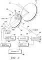
- FIGS 1-4 show a construction of antenna 20 and the manner in which the antenna 20 can be deployed on board a communications satellite 22 (Figure l) and stowed on the satellite 22 within a launch vehicle's shroud 22A ( Figure 2) prior to launch.
- the antenna 20 is operative to transmit and receive microwave radiation to and from ground stations on the earth, and comprises a main reflector 24, a subreflector 26, an S-band feed 28, and a C-band feed 30.
- the subreflector 26 has a frequency selective surface (FSS) 32 which is operative to reflect the relatively low frequency S-band radiation of the S-band feed 28, and is operative in a transparent mode to transmit the relatively high frequency C-band radiation of the C-band feed 30.
- FSS frequency selective surface
- the subreflector 26 is positioned in front of the main reflector 24, the S-band feed 28 is located behind and to the side of the subreflector 26, and the C-band feed 30 is located forward and to the side of the subreflector 26.
- This arrangement of the antenna components allows the components to be mounted conveniently upon a housing 34 of the satellite 22.
- this arrangement of the antenna components allows radiation from the S-band feed 28 to be reflected by the FSS 32 to the main reflector 24, while allowing concurrently radiation from the C-band feed 30 to propagate along a linear optical path through the FSS 32 directly to the main reflector 24.
- the main reflector 24 has a curved reflecting surface 36 which is operative in conjunction with radiators (to be described hereinafter) of the feeds 28 and 30 to form beams of radiation at the S-band and the C-band band frequencies.
- the antenna 20 is operative with one S-band signal channel in one portion of the electromagnetic spectrum, and with two C-band signal channels in two separate portions of the spectrum.
- the S-band signal channel is in the frequency band of 2.655 - 2.690 GHz (gigahertz), this band being reflected by the FSS 32.
- One of the C-band channels is in the frequency band of 3.7 - 4.2 GHz, this band being passed by the FSS 32 and serving as a transmit signal channel for transmission of signals from the C-band feed 30.
- the second of the C-band channels is in the frequency band of 5.925 - 6.425 GHz, this band being passed by the FSS 32 and serving as a receive signal channel for reception of signals by the C-band feed 30.
- Figure 4 demonstrates the propagation paths of rays of radiation, in the deployed configuration of the antenna 20, between the feeds 28, 30 and the main reflector 24.
- Rays 38 of S-band radiation- indicated by short dashes, propagate along optical paths which are folded at the FSS 32, the optical paths of the rays 38 extending from the S-band feed 28 via the FSS 32 of the subreflector 26 to the reflecting surface 36 of the main reflector 24.
- Rays 40 of C-band radiation indicated by long dashes, propagate along the aforementioned straight optical paths from the C-band feed 30 through the FSS 32 to the reflecting surface 36 of the main reflector 24.
- the C-band feed 30 lies at the focus of the reflecting surface 36 of the main reflector 24.
- the subreflector 26 has a substrate 42 for supporting the FSS 32, the substrate 42 being transparent to the C/S band radiations.
- the FSS 32 comprises an array of resonators or radiating elements 44 disposed on a front surface 46 of the substrate 42.
- the front surface 46 lies within a plane 48 which is equidistant and symmetrically positioned between the feeds 28 and 30. This provides for a geometrical arrangement of the antenna components such that the S-band rays 38, if traced back from the main reflector 24 through the FSS, would converge upon the location of the C-band feed 30.
- the S-band feed 28 is located at a reflected virtual focal point of the main reflector 24.
- the stowing of the antenna 20 is accomplished by providing hinges 50 and 52, respectively, for the main reflector 24 and the subreflector 26, the hinges 50 and 52 being disposed on the satellite housing 34 ( Figure 1).
- the hinges 50 and 52 enable the main reflector 24 and the subreflector 26 to be pivoted relative to the housing 34 from the stowed position of Figure 2 to the deployed position of Figure 1.
- a portion of the hinge 50 includes a straight arm 54 extending from the main reflector 24 to engage with a pivot 56 of the hinge 50.
- a portion of the hinge 52 includes a bent arm 58 extending from the subreflector 26 to engage with a pivot 60 of the hinge 52.
- a hold-down 62 ( Figure 2) secures the antenna 20 to the satellite 22 in the stowed condition of the antenna 20. Stowing of the antenna 20 is accomplished by first pivoting the subreflector 36 to a position adjacent the C-band feed 30 followed by a pivoting of the main reflector 24 to a position adjacent to both the S-band feed 28 and the stowed subreflector 26.
- the stowing of the antenna 20 provides for such a compact configuration antenna that, if desired, a second similarly constructed antenna 64 can be provided, as shown in its deployed position in Figure 1.
- a main reflector is pivotal from a stowed position to a deployed position
- suitable deployment devices for bringing the reflector into its desired orientation and for maintaining the desired orientation are presently available. Such devices are employed in the practice of the invention, and need not be described in detail herein for an understanding of the invention.
- Figure 3 shows spatial relationships among the antenna components upon a deploying of the antenna 20.
- the reflecting surface 36 of the main reflector 24 is an offset paraboloidal reflecting surface.
- a reference line C joins the antenna focus, at the C-band feed 30, to the virtual focal point of the antenna 20, at the S-band feed 28.
- a second reference line D extends from the antenna focus at the C-band feed 30 to the vertex of the paraboloidal surface of the main reflector 24.
- the FSS of the subreflector 26 is flat, intersects the line C, and is perpendicular to the line C.
- Angulation of line C relative to line D is shown in Figure 3. Also shown is angulation of a central ray E of the C-band feed 30 relative to the line D, as well as the orientation of extreme rays F and G.
- the invention permits the construction of a relatively large antenna, as compared to presently available antennas, such that the distance A between the C-band feed 30 and the parabola vertex is 104 feet, and wherein the spacing 2B between the feeds 28 and 30 is 42 feet.
- FIG. 5 shows further details of the antenna 20 and also, by way of example, a portion of a communication system 66 employing the antenna 20.
- Figure 5 shows a portion of an array 68 of the radiating elements 44 of the FSS.
- Each of the radiating elements 44 comprises a nested set of annular radiators 70 of successively larger size wherein one of the radiators enclosed another of the radiators.
- Three radiators 70 are shown, by way of example, in each of the radiating elements 44, and wherein an outermost one of the radiators 70 in each of the radiating elements 44 is hexagonal.
- the use of the outer hexagonal radiator 70 permits a closer spacing of the radiating elements 44 to obtain improved antenna performance in terms of increased bandwidth and operation of the FSS with increased beam width for each of the feeds 28 and 30. Further details in the construction of the FSS will be provided hereinafter.
- the C-band feed 30 has two orthogonal ports 72 and 74.
- the port 72 serves to input signals for transmission by the feed 30 in the aforementioned transmission signal channel.
- the port 74 serves to output signals received by the feed 30 in the aforementioned reception signal channel.
- Transmission is indicated by a ray 4OT of radiation
- reception is indicated by a ray 40R of radiation.
- electromagnetic waves represented by the rays 40T and 40R are circularly polarized with opposite senses of polarization.
- the transmitted wave may have a right hand circular polarization
- the received wave may have a left hand circular polarization.
- the rays 4OT and 40R are portrayed by long dashes, and the ray 38 from the S-band feed 28 is portrayed by short dashes. Beams of C and 5 band radiation produced by the antenna 20 are indicated at 76.
- the communication system 66 includes a receiver 78, a transmitter 80, a transceiver 82, and a signal processor 84.
- the antenna 20 includes a receive beamformer 86 which connects with the receiver 78, and a transmit beamformer 88 which connects with the transmitter 80.
- the beamformers 86 and 88 are formed within the structure of the C-band feed 30.
- the transceiver 82 connects with the S-band feed 28.
- the S-band signal channel can be used for either reception or transmission of signals and, accordingly, the transceiver 82 has been provided to enable either a transmission or a reception of microwave signals as may be desired.
- Connections are provided between the signal processor 84 and the transceiver 82 as well as with the receiver 78 and the transmitter 80.
- one of a plurality of communication channels in one spectral band is employed for an up-link signal transmission, and another of the plurality of signal transmission bands is a separate portion of the electromagnetic spectrum is employed for the down-link transmission of signals.
- the system 66 provides for a generalized situation wherein the S-band signal channel may be employed for either up-link or down-link transmission and the two C-band channels are operative concurrently for both up-link or down-link transmissions.
- an up-link signal from a ground station to the satellite is incident upon the antenna 20, and propagates via the C-band feed 30, including the port 74, and the receive beamformer 86, to the receiver 78.
- the receiver 78 applies the received signal to the signal processor 84 which, by way of example, may demodulate the signal, filter the signal, and modulate the signal onto a further carrier suitable for retransmission, thereby to transfer a signal from an up-link transmission band to a down-link transmission band for transmission back to a location an the earth.
- the signal is outputted by the signal processor 84 to the transmitter 80 which transmits the signal via the C-band feed 30, including the transmit beamformer 88 and the port 72, to be radiated by the antenna 20 in a down-link beam.
- the signal processor 84 may present to the signal processor 84 by the transceiver 82, or a down-link signal may be transmitted from the signal processor 84 via the transceiver 82.
- FIG. 6 shows further details in the construction of the main reflector 24.
- the reflector 24 includes a frame 90 located on a back side of the reflecting surface 36.
- the frame 90 has longitudinal struts 92 and transverse struts 94 to provide dimensional stability to the reflecting surface 36.
- the hinge 50 is shown partially in Figure 6, the hinge 50 connecting via its arm 54 to the frame 90 to enable pivoting of the main reflector 24 about the pivot 56.
- FIG. 7 shows details in the construction of the S-band feed 28.
- the feed 28 comprises, by way of example as constructed in a preferred embodiment of the invention, seven helical radiating elements 96 supported by a base 98.
- five of the radiating elements 96 are shown only in outline form.
- Four of the elements 96 are active, as indicated in the drawing, for producing four independent beams directed toward the earth.
- the remaining three of the elements 96 are dummy elements, as indicated in the drawing, for balancing mutual coupling effects of the active helical elements, thereby to avoid a squinting of the beams away from each other for improved accuracy in defining earth coverage by the respective beams.
- the base 98 is fabricated of an electrically conductive material, such as a metal, to serve as a ground plane for the radiating elements 96.
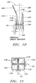
- FIGS. 8-14 provide details in the construction of the C-band feed 30.
- the feed 30 comprises an array of radiators 100 which are upstanding from a supporting metallic base 102 which serves as a ground plane of the feed 30.
- Each of the radiators 100 comprises a straight section of waveguide 100 of square cross section, and a flared horn 106 communicating with the waveguide section 104.
- Each of the radiators 100 is fabricated of electroformed copper.
- a meanderline polarizer 108 extends across the radiating apertures of the respective horns 106.
- Each of the waveguide sections 104 has four sidewalls 110, and the ports 72 and 74 are located in a pair of abutting ones of the sidewalls 110 to provide for the orthogonal arrangement of feeding electromagnetic signals into and out of a radiator 100.
- Each of the ports 72 and 74 comprises a coaxial feed 112 having an inner conductor 114 enclosed within an outer conductor ⁇ 116.
- Four ridges 118 are provided in each radiator 100, there being one ridge 118 extending inwardly from a central portion of each sidewall 110 to provide a quad-ridge configuration.
- the ridges 118 extend along each radiator 110 in a direction parallel to a longitudinal axis 120 from a back wall 122 of the waveguide section 104 to the radiating aperture 124 at the front of the horn 106.
- Each of the ridges 118 has a maximum depth at the back end of the radiator 100, in the vicinity of the back wall 122, and then tapers through the waveguide section 104 and within the horn 106 to a zero depth at the radiating aperture 124.
- the coaxial feeds 112 are located within individual ones of the ridges 118.
- the coaxial feed 112 extends across the axis 120 into the opposite ridge 118, the amount of extension of the inner conductor 114 being adjusted to provide for the desired impedance match.
- the ridges 118 are operative to provide increased bandwidth to each of the radiators 100.
- Each of the ports 72 and 74 is capable of launching a single linearly polarized wave within the radiator 100.
- the linearly polarized waves are orthogonal to each other.
- the meanderline polarizer 108 is operative to convert one of the linearly polarized waves to right-hand circular polarization, and to convert the other of the linearly polarized waves to left-hand circular polarization in each of the radiators 100.
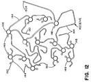
- the receive beamformer 86 and the transmit beamformer 88 which are constructed as barline circuit networks in laminar form, the two beamformers 86 and 88 being separated by a metallic layer 126 which serves as a ground plane and isolates the circuits of the beamformers 86 and 88 from each other.
- a fragmentary portion 128 of the barline network of the receive beamformer 86 is shown in Figure 14, the portion 128 comprising a barline center conductor 130 disposed within a layer 132 of honeycomb dielectric material, an upper aluminum honeycomb layer 134 sandwiched between a first face skin 136 of electrically insulating dielectric material and a second face skin 138 of electrically insulating dielectric material, and a lower aluminum honeycomb layer 140 sandwiched between a first face skin 142 of electrically insulating dielectric material and a second face skin 144 of electrically insulating dielectric material.
- the constructional features of the portion 128 apply also to the construction of the transmit beamformer 88 and, accordingly, no sectional view of the beamformer 88 need be provided.
- Figures 12 and 13 show plan views of the circuit barline networks of the receive beamformer 86 and the transmit beamformer 88, respectively.
- the networks of each of the beamformers 86 and 88 include barline segments 144 of specific lengths to introduce phase shifts among the radiators 100 (Figure 8), circular power dividers 146 connected to the barline segments 144 for dividing power among the radiators 100, loads 148 connected to the barline segments 144 for matching line impedance (typically 50 ohms), and connections 150 to the port 74 ( Figure 8) in the case of the receive beamformer 86 or to the port 72 in the case of the transmit beamformer 88.
- Each of the connections 150 comprise a feed-through element 152, two of the feed-through elements 152 being identified in Figure 9.
- the power dividers 146 can act also in reciprocal fashion so as to serve as a power combiner in the receive beamformer 86 while serving to divide power in the transmit beamformer 88.
- one of the connectors 150R connects with a coaxto-waveguide transition 154 on top of the base 102 ( Figure 8) for connection to the receiver 78 of Figure 5.
- one of the connectors 150T connects with a coax-to-waveguide transition 156 on top of the base 102 ( Figures 8 and 9) for connection to the transmitter 80 of Figure 5.
- the receive beamformer 86 In the operation of the receive beamformer 86, power received at the C-band feed 30 with the requisite sense of the circular polarization is converted by the meanderline polarizer 108 to a linearly polarized wave which propagates along each of the radiators 100, is extracted by the respective receive ports 74 and is applied to the connections 150 of the beamformer 86. Via the power dividers (combiners) 146, the beamformer 86 sums the signals from the respective radiators 100 with appropriate phase shift being provided by the barline segments 144 to obtain a receive beam and to output power of the receive beam to the receiver 78.
- the receiver has a pass band tuned to reception of the received signal while excluding the spectrum of the transmit signal.
- a signal applied by the transmitter 80 is divided by the power dividers 146 among the transmit ports 72 of the respective radiators 100 with appropriate phase shift being provided by the barline segments 144 for generating the transmit beam from the array of the radiators 100.
- each of the radiators 70 is formed as a closed, generally circular path of electrically conductive material, a metal such as copper or aluminum being employed in the preferred embodiment of the invention.
- the substrate 42 is fabricated of dielectric materials, all of which are transparent to the C-band and the S-band electromagnetic radiation.
- the outermost one of the radiators is identified as 70A
- the innermost one of the radiators is identified as 70C
- the middle radiator is identified as 70B.
- the spacing, D, between the centers 158 of the radiating elements 44, and the closest point of approach, d, between adjacent radiating elements 44 are indicated in Figure 15.
- the inner and the outer radii r1 and r2 of the innermost radiator 70C are shown in Figures 15 and 17.
- the inner and outer radii r3 and r4 of the middle radiator 70B are indicated also in Figures 15 and 17.
- the difference in radii, r2-r1, and the difference in radii r4-r3 provide the width of the innermost and the middle radiators 70C and 70B.
- the width of the outermost radiator 70A is given by W, as shown in Figure 17.
- Adjacent ones of the radiating elements 44 have their centers 158 arranged at the vertices of an equilateral triangle, as shown in Figure 15, wherein each side of the triangle is identified by the distance D.
- the length L of one side of the hexagon of the outermost radiator 70A in any one of the radiating elements 44 is shown also in Figure 15.
- the substrate 42 has a lightweight rigid construction which is advantageous in satellite antenna systems.
- the substrate 42 comprises a central honeycomb core 160 enclosed on front and back sides by layers 162 and 164 of plastic film material, such as a polycarbonate, a layer of Kevlar being used in the construction of the front and back layers 162 and 164 in the preferred embodiment of the invention.
- a relatively thin layer 166 of plastic material such as nylon or Upilex is secured adhesively to the front layer 162 to serve as a bed for deposition of the radiator 40, the Upilex being employed in the preferred embodiment of the invention.
- the honeycomb core 160 has a dielectric constant, similar to that of air, and may be formed of a material such as craft paper, such a material, Nomax being employed in a preferred embodiment of the invention.
- the radiators 70 are fabricated of copper film deposited in a layer in a range of typically 5 - 10 mil thickness. The minimum thickness should be equal to at least a few times the electromagnetic skin depth of the copper film.
- the width W of the radiator 70A has a value in the range of 0.01 - 0.0 ⁇ 2 inch, a value of 0.015 inch being employed in the preferred embodiment of the invention.
- radiator 70A This provides for a circumference of the radiator 70A approximately equal to the wavelength of the S-band radiation within the dielectric material of the substrate, thereby enabling the radiator 70A to resonate at the frequency of the S-band radiation.
- construction of the inner annular C-band radiators 70B and 70C with mean values of circumference equal approximately to mean values of their respective bands of radiation allow these radiators to resonate at their respective frequencies.
- the distance D between the centers is equal to 1.73 L which is equal to approximately one-third wavelength of the S-band radiation in the dielectric substrate, these being equal approximately to 0.770 inches in the preferred embodiment of the invention.
- the closest point of approach, d is equal to 15 mils.
- the radii r1, r2 , r3 and r4 are equal respectively to 0.70 inches, 0.265 inches, 0.275 inches, and 0.335 inches.
- the following dimensions are used in the construction of the substrate 42.
- the Kevlar layers 162 and 164 each have a thickness in the range of 10 - 20 mils.
- the honeycomb core 160 has a thickness of one inch.
- the Upilex layer 166 has a thickness in the range of 1 -2 mils.
- the dielectric constant of the layers 162, 164, and 166 is in the range of approximately 2.2 -2.8.
- the invention has provided for a multiple channel satellite communication antenna employing a plural channel C-band feed and a single channel S-band feed which are operative concurrently with a single main reflector by use of a subreflector constructed as an FSS.
Landscapes
- Physics & Mathematics (AREA)
- Engineering & Computer Science (AREA)
- Astronomy & Astrophysics (AREA)
- General Physics & Mathematics (AREA)
- Remote Sensing (AREA)
- Aviation & Aerospace Engineering (AREA)
- Aerials With Secondary Devices (AREA)
- Variable-Direction Aerials And Aerial Arrays (AREA)
Priority Applications (1)
| Application Number | Priority Date | Filing Date | Title |
|---|---|---|---|
| EP97201505A EP0803932B1 (fr) | 1994-06-22 | 1995-02-16 | Antenne pliable pour plusieurs bandes de fréquences |
Applications Claiming Priority (2)
| Application Number | Priority Date | Filing Date | Title |
|---|---|---|---|
| US08/263,558 US5557292A (en) | 1994-06-22 | 1994-06-22 | Multiple band folding antenna |
| US263558 | 1994-06-22 |
Related Child Applications (1)
| Application Number | Title | Priority Date | Filing Date |
|---|---|---|---|
| EP97201505A Division EP0803932B1 (fr) | 1994-06-22 | 1995-02-16 | Antenne pliable pour plusieurs bandes de fréquences |
Publications (3)
| Publication Number | Publication Date |
|---|---|
| EP0689264A2 true EP0689264A2 (fr) | 1995-12-27 |
| EP0689264A3 EP0689264A3 (fr) | 1996-11-06 |
| EP0689264B1 EP0689264B1 (fr) | 1999-10-20 |
Family
ID=23002268
Family Applications (2)
| Application Number | Title | Priority Date | Filing Date |
|---|---|---|---|
| EP97201505A Expired - Lifetime EP0803932B1 (fr) | 1994-06-22 | 1995-02-16 | Antenne pliable pour plusieurs bandes de fréquences |
| EP95300997A Expired - Lifetime EP0689264B1 (fr) | 1994-06-22 | 1995-02-16 | Antenne pliable pour plusieurs bandes de fréquences |
Family Applications Before (1)
| Application Number | Title | Priority Date | Filing Date |
|---|---|---|---|
| EP97201505A Expired - Lifetime EP0803932B1 (fr) | 1994-06-22 | 1995-02-16 | Antenne pliable pour plusieurs bandes de fréquences |
Country Status (5)
| Country | Link |
|---|---|
| US (1) | US5557292A (fr) |
| EP (2) | EP0803932B1 (fr) |
| JP (1) | JPH0818331A (fr) |
| CA (1) | CA2140507C (fr) |
| DE (2) | DE69512684T2 (fr) |
Cited By (5)
| Publication number | Priority date | Publication date | Assignee | Title |
|---|---|---|---|---|
| EP1189301A3 (fr) * | 2000-09-15 | 2003-07-09 | Space Systems / Loral, Inc. | Système de déploiement et de stockage pour réflecteur primaire et secondaire |
| EP1810372A4 (fr) * | 2004-10-15 | 2008-09-03 | Harris Corp | Alimentation simultanee en bande large d'antenne a reflecteur a focalisation annulaire multibande |
| EP2911241A1 (fr) * | 2014-02-20 | 2015-08-26 | Agence Spatiale Europeenne | Antenne à réflecteur à faisceaux multiples à double bande pour satellites à large bande |
| WO2016205715A1 (fr) * | 2015-06-19 | 2016-12-22 | Hughes Network Systems, Llc | Terminal terrestre de télécommunication par satellite utilisant un diplexeur à surface sélective en fréquence |
| US10658757B2 (en) | 2015-06-19 | 2020-05-19 | Hughes Network Systems, Llc | Satellite ground terminal utilizing frequency-selective surface subreflector |
Families Citing this family (55)
| Publication number | Priority date | Publication date | Assignee | Title |
|---|---|---|---|---|
| GB9811850D0 (en) * | 1998-06-02 | 1998-07-29 | Cambridge Ind Ltd | Antenna feeds |
| US6211834B1 (en) | 1998-09-30 | 2001-04-03 | Harris Corporation | Multiband ring focus antenna employing shaped-geometry main reflector and diverse-geometry shaped subreflector-feeds |
| DE19945062A1 (de) * | 1999-09-20 | 2001-04-12 | Daimler Chrysler Ag | Reflektor mit geformter Oberfläche und räumlich getrennten Foki zur Ausleuchtung identischer Gebiete, Antennensystem und Verfahren zur Oberflächenermittlung |
| US6512485B2 (en) | 2001-03-12 | 2003-01-28 | Wildblue Communications, Inc. | Multi-band antenna for bundled broadband satellite internet access and DBS television service |
| US6433752B1 (en) * | 2001-04-13 | 2002-08-13 | The Boeing Company | Multiple antenna reflectors for microwave imaging and sounding |
| US7038632B2 (en) * | 2001-09-14 | 2006-05-02 | Andrew Corporation | Co-located multi-band antenna |
| US6844862B1 (en) * | 2002-02-11 | 2005-01-18 | Lockheed Martin Corporation | Wide angle paraconic reflector antenna |
| US6759994B2 (en) * | 2002-07-26 | 2004-07-06 | The Boeing Company | Multiple beam antenna using reflective and partially reflective surfaces |
| CN1989652B (zh) | 2004-06-28 | 2013-03-13 | 脉冲芬兰有限公司 | 天线部件 |
| FI20055420A0 (fi) | 2005-07-25 | 2005-07-25 | Lk Products Oy | Säädettävä monikaista antenni |
| FI119009B (fi) * | 2005-10-03 | 2008-06-13 | Pulse Finland Oy | Monikaistainen antennijärjestelmä |
| FI118872B (fi) | 2005-10-10 | 2008-04-15 | Pulse Finland Oy | Sisäinen antenni |
| FI118782B (fi) | 2005-10-14 | 2008-03-14 | Pulse Finland Oy | Säädettävä antenni |
| KR100753552B1 (ko) * | 2006-07-07 | 2007-08-30 | 한국전자통신연구원 | 단일 주파수 대역 필터링 용 fss 구조 |
| US8618990B2 (en) | 2011-04-13 | 2013-12-31 | Pulse Finland Oy | Wideband antenna and methods |
| WO2008045151A1 (fr) * | 2006-10-05 | 2008-04-17 | Pulse Finland Oy | Antenne multibandes avec une structure d'alimentation résonante commune et procédés correspondants |
| US10211538B2 (en) | 2006-12-28 | 2019-02-19 | Pulse Finland Oy | Directional antenna apparatus and methods |
| FI20075269A0 (fi) | 2007-04-19 | 2007-04-19 | Pulse Finland Oy | Menetelmä ja järjestely antennin sovittamiseksi |
| FI120427B (fi) | 2007-08-30 | 2009-10-15 | Pulse Finland Oy | Säädettävä monikaista-antenni |
| FI124129B (fi) * | 2007-09-28 | 2014-03-31 | Pulse Finland Oy | Kaksoisantenni |
| FI20096134A0 (fi) | 2009-11-03 | 2009-11-03 | Pulse Finland Oy | Säädettävä antenni |
| FI20096251A0 (sv) | 2009-11-27 | 2009-11-27 | Pulse Finland Oy | MIMO-antenn |
| US8847833B2 (en) | 2009-12-29 | 2014-09-30 | Pulse Finland Oy | Loop resonator apparatus and methods for enhanced field control |
| FI20105158A7 (fi) | 2010-02-18 | 2011-08-19 | Pulse Finland Oy | Kuorisäteilijällä varustettu antenni |
| US9406998B2 (en) | 2010-04-21 | 2016-08-02 | Pulse Finland Oy | Distributed multiband antenna and methods |
| EP2643882B1 (fr) | 2010-12-15 | 2014-04-16 | Skybox Imaging, Inc. | Système d'antenne intégrée pour microsatellites d'imagerie |
| FI20115072A0 (fi) | 2011-01-25 | 2011-01-25 | Pulse Finland Oy | Moniresonanssiantenni, -antennimoduuli ja radiolaite |
| US9673507B2 (en) | 2011-02-11 | 2017-06-06 | Pulse Finland Oy | Chassis-excited antenna apparatus and methods |
| US8648752B2 (en) | 2011-02-11 | 2014-02-11 | Pulse Finland Oy | Chassis-excited antenna apparatus and methods |
| US8866689B2 (en) | 2011-07-07 | 2014-10-21 | Pulse Finland Oy | Multi-band antenna and methods for long term evolution wireless system |
| US9450291B2 (en) | 2011-07-25 | 2016-09-20 | Pulse Finland Oy | Multiband slot loop antenna apparatus and methods |
| US9123990B2 (en) | 2011-10-07 | 2015-09-01 | Pulse Finland Oy | Multi-feed antenna apparatus and methods |
| US9531058B2 (en) | 2011-12-20 | 2016-12-27 | Pulse Finland Oy | Loosely-coupled radio antenna apparatus and methods |
| US9484619B2 (en) | 2011-12-21 | 2016-11-01 | Pulse Finland Oy | Switchable diversity antenna apparatus and methods |
| US8988296B2 (en) | 2012-04-04 | 2015-03-24 | Pulse Finland Oy | Compact polarized antenna and methods |
| US9979078B2 (en) | 2012-10-25 | 2018-05-22 | Pulse Finland Oy | Modular cell antenna apparatus and methods |
| JPWO2014073445A1 (ja) * | 2012-11-06 | 2016-09-08 | シャープ株式会社 | 一次放射器 |
| US10069209B2 (en) | 2012-11-06 | 2018-09-04 | Pulse Finland Oy | Capacitively coupled antenna apparatus and methods |
| US10079428B2 (en) | 2013-03-11 | 2018-09-18 | Pulse Finland Oy | Coupled antenna structure and methods |
| US9647338B2 (en) | 2013-03-11 | 2017-05-09 | Pulse Finland Oy | Coupled antenna structure and methods |
| US9634383B2 (en) | 2013-06-26 | 2017-04-25 | Pulse Finland Oy | Galvanically separated non-interacting antenna sector apparatus and methods |
| US9680212B2 (en) | 2013-11-20 | 2017-06-13 | Pulse Finland Oy | Capacitive grounding methods and apparatus for mobile devices |
| US9590308B2 (en) | 2013-12-03 | 2017-03-07 | Pulse Electronics, Inc. | Reduced surface area antenna apparatus and mobile communications devices incorporating the same |
| US9350081B2 (en) | 2014-01-14 | 2016-05-24 | Pulse Finland Oy | Switchable multi-radiator high band antenna apparatus |
| US9973228B2 (en) | 2014-08-26 | 2018-05-15 | Pulse Finland Oy | Antenna apparatus with an integrated proximity sensor and methods |
| US9948002B2 (en) | 2014-08-26 | 2018-04-17 | Pulse Finland Oy | Antenna apparatus with an integrated proximity sensor and methods |
| US9722308B2 (en) | 2014-08-28 | 2017-08-01 | Pulse Finland Oy | Low passive intermodulation distributed antenna system for multiple-input multiple-output systems and methods of use |
| US9906260B2 (en) | 2015-07-30 | 2018-02-27 | Pulse Finland Oy | Sensor-based closed loop antenna swapping apparatus and methods |
| US10153559B1 (en) * | 2016-06-23 | 2018-12-11 | Harris Corporation | Modular center fed reflector antenna system |
| CN107196065B (zh) * | 2017-04-28 | 2020-01-07 | 湖南航天环宇通信科技股份有限公司 | 大型可展开固面天线 |
| US10673146B1 (en) * | 2017-07-31 | 2020-06-02 | United States Of America As Represented By The Administrator Of National Aeronautics And Space Administration | Hybrid communication system including a mounting structure for an optical element |
| CN108091997B (zh) * | 2018-01-30 | 2023-08-01 | 厦门大学嘉庚学院 | 一种嵌套感应-六边形阵列复合超宽频带天线及终端 |
| WO2021140517A1 (fr) | 2020-01-09 | 2021-07-15 | Nsl Comm Ltd | Système de communication à faisceau multipoint compact pour satellite de petite taille |
| CN114094347B (zh) | 2020-08-24 | 2023-07-18 | 华为技术有限公司 | 多频段天线系统和基站 |
| CN115377684B (zh) * | 2021-05-21 | 2026-04-21 | 威海蓝天科技有限公司 | 基于频率选择表面的主被动复合宽带天线装置 |
Family Cites Families (12)
| Publication number | Priority date | Publication date | Assignee | Title |
|---|---|---|---|---|
| US3395059A (en) * | 1964-04-15 | 1968-07-30 | Sylvania Electric Prod | Method of making lightweight horn antenna |
| GB2065377B (en) * | 1979-12-10 | 1984-05-16 | Marconu Co Ltd | Combined radar communication system |
| DE3023562C2 (de) * | 1980-06-24 | 1982-10-28 | Siemens AG, 1000 Berlin und 8000 München | Einrichtung zur Polarisationsumwandlung elektromagnetischer Wellen |
| FR2517626A1 (fr) * | 1981-12-04 | 1983-06-10 | Europ Agence Spatiale | Engin spatial orbital, notamment satellite, a missions multiples |
| US5086304A (en) * | 1986-08-13 | 1992-02-04 | Integrated Visual, Inc. | Flat phased array antenna |
| US4792813A (en) * | 1986-08-14 | 1988-12-20 | Hughes Aircraft Company | Antenna system for hybrid communications satellite |
| US4972199A (en) * | 1989-03-30 | 1990-11-20 | Hughes Aircraft Company | Low cross-polarization radiator of circularly polarized radiation |
| US5258771A (en) * | 1990-05-14 | 1993-11-02 | General Electric Co. | Interleaved helix arrays |
| US5162809A (en) * | 1990-10-23 | 1992-11-10 | Hughes Aircraft Company | Polarization independent frequency selective surface for diplexing two closely spaced frequency bands |
| US5373302A (en) * | 1992-06-24 | 1994-12-13 | The United States Of America As Represented By The Administrator Of The National Aeronautics And Space Administration | Double-loop frequency selective surfaces for multi frequency division multiplexing in a dual reflector antenna |
| US5283587A (en) * | 1992-11-30 | 1994-02-01 | Space Systems/Loral | Active transmit phased array antenna |
| US5471224A (en) * | 1993-11-12 | 1995-11-28 | Space Systems/Loral Inc. | Frequency selective surface with repeating pattern of concentric closed conductor paths, and antenna having the surface |
-
1994
- 1994-06-22 US US08/263,558 patent/US5557292A/en not_active Expired - Lifetime
-
1995
- 1995-01-18 CA CA002140507A patent/CA2140507C/fr not_active Expired - Fee Related
- 1995-02-16 DE DE69512684T patent/DE69512684T2/de not_active Expired - Fee Related
- 1995-02-16 EP EP97201505A patent/EP0803932B1/fr not_active Expired - Lifetime
- 1995-02-16 DE DE69512839T patent/DE69512839T2/de not_active Expired - Fee Related
- 1995-02-16 EP EP95300997A patent/EP0689264B1/fr not_active Expired - Lifetime
- 1995-04-05 JP JP7080421A patent/JPH0818331A/ja active Pending
Cited By (7)
| Publication number | Priority date | Publication date | Assignee | Title |
|---|---|---|---|---|
| EP1189301A3 (fr) * | 2000-09-15 | 2003-07-09 | Space Systems / Loral, Inc. | Système de déploiement et de stockage pour réflecteur primaire et secondaire |
| EP1810372A4 (fr) * | 2004-10-15 | 2008-09-03 | Harris Corp | Alimentation simultanee en bande large d'antenne a reflecteur a focalisation annulaire multibande |
| EP2911241A1 (fr) * | 2014-02-20 | 2015-08-26 | Agence Spatiale Europeenne | Antenne à réflecteur à faisceaux multiples à double bande pour satellites à large bande |
| US9478861B2 (en) | 2014-02-20 | 2016-10-25 | Agence Spatiale Europeene | Dual-band multiple beam reflector antenna for broadband satellites |
| WO2016205715A1 (fr) * | 2015-06-19 | 2016-12-22 | Hughes Network Systems, Llc | Terminal terrestre de télécommunication par satellite utilisant un diplexeur à surface sélective en fréquence |
| US10559888B2 (en) | 2015-06-19 | 2020-02-11 | Hughes Network Systems, Llc | Satellite ground terminal utilizing frequency-selective surface diplexer |
| US10658757B2 (en) | 2015-06-19 | 2020-05-19 | Hughes Network Systems, Llc | Satellite ground terminal utilizing frequency-selective surface subreflector |
Also Published As
| Publication number | Publication date |
|---|---|
| DE69512684D1 (de) | 1999-11-11 |
| EP0803932A1 (fr) | 1997-10-29 |
| JPH0818331A (ja) | 1996-01-19 |
| CA2140507A1 (fr) | 1995-12-23 |
| EP0689264B1 (fr) | 1999-10-20 |
| EP0689264A3 (fr) | 1996-11-06 |
| US5557292A (en) | 1996-09-17 |
| EP0803932B1 (fr) | 1999-10-06 |
| DE69512684T2 (de) | 2000-03-09 |
| DE69512839D1 (de) | 1999-11-25 |
| DE69512839T2 (de) | 2000-05-18 |
| CA2140507C (fr) | 2002-10-01 |
Similar Documents
| Publication | Publication Date | Title |
|---|---|---|
| EP0689264B1 (fr) | Antenne pliable pour plusieurs bandes de fréquences | |
| US11715880B2 (en) | Waveguide feed network architecture for wideband, low profile, dual polarized planar horn array antennas | |
| US5471224A (en) | Frequency selective surface with repeating pattern of concentric closed conductor paths, and antenna having the surface | |
| US5576721A (en) | Composite multi-beam and shaped beam antenna system | |
| US4115782A (en) | Microwave antenna system | |
| US4343005A (en) | Microwave antenna system having enhanced band width and reduced cross-polarization | |
| US5543809A (en) | Reflectarray antenna for communication satellite frequency re-use applications | |
| US5793334A (en) | Shrouded horn feed assembly | |
| US5485167A (en) | Multi-frequency band phased-array antenna using multiple layered dipole arrays | |
| US5818396A (en) | Launcher for plural band feed system | |
| US5907309A (en) | Dielectrically loaded wide band feed | |
| US20040008153A1 (en) | Single and dual-band patch/helix antenna arrays | |
| US12288933B2 (en) | Antenna system for satellite applications | |
| EP0390350B1 (fr) | Source pour ondes à polarisation circulaire à faible polarisation croisée | |
| US5793335A (en) | Plural band feed system | |
| JP2003143051A (ja) | 衛星用の反射鏡アンテナ・システム | |
| US6329957B1 (en) | Method and apparatus for transmitting and receiving multiple frequency bands simultaneously | |
| Gurbet et al. | Comprehensive review of ku, k, and ka band antenna designs: Applications in cubesats | |
| WO2001065641A1 (fr) | Antenne reglable | |
| US7843392B2 (en) | Dual frequency antenna system | |
| US5995056A (en) | Wide band tem fed phased array reflector antenna | |
| Abd El-Rahman et al. | Dual-Band Cavity-Backed KA-band antenna for satellite communication | |
| JPH03106103A (ja) | 2周波数共用アレイフィード | |
| CN107919536B (zh) | 用于卫星通信的双线极化天线馈源阵列及卫星通信天线 | |
| JPH0195608A (ja) | 複反射鏡アンテナ |
Legal Events
| Date | Code | Title | Description |
|---|---|---|---|
| PUAI | Public reference made under article 153(3) epc to a published international application that has entered the european phase |
Free format text: ORIGINAL CODE: 0009012 |
|
| AK | Designated contracting states |
Kind code of ref document: A2 Designated state(s): DE FR GB IT |
|
| PUAL | Search report despatched |
Free format text: ORIGINAL CODE: 0009013 |
|
| AK | Designated contracting states |
Kind code of ref document: A3 Designated state(s): DE FR GB IT |
|
| 17P | Request for examination filed |
Effective date: 19970117 |
|
| GRAG | Despatch of communication of intention to grant |
Free format text: ORIGINAL CODE: EPIDOS AGRA |
|
| 17Q | First examination report despatched |
Effective date: 19981201 |
|
| GRAG | Despatch of communication of intention to grant |
Free format text: ORIGINAL CODE: EPIDOS AGRA |
|
| GRAH | Despatch of communication of intention to grant a patent |
Free format text: ORIGINAL CODE: EPIDOS IGRA |
|
| GRAH | Despatch of communication of intention to grant a patent |
Free format text: ORIGINAL CODE: EPIDOS IGRA |
|
| GRAA | (expected) grant |
Free format text: ORIGINAL CODE: 0009210 |
|
| AK | Designated contracting states |
Kind code of ref document: B1 Designated state(s): DE FR GB IT |
|
| DX | Miscellaneous (deleted) | ||
| REF | Corresponds to: |
Ref document number: 69512839 Country of ref document: DE Date of ref document: 19991125 |
|
| ET | Fr: translation filed | ||
| ITF | It: translation for a ep patent filed | ||
| RAP4 | Party data changed (patent owner data changed or rights of a patent transferred) |
Owner name: SPACE SYSTEMS / LORAL, INC. |
|
| PLBE | No opposition filed within time limit |
Free format text: ORIGINAL CODE: 0009261 |
|
| STAA | Information on the status of an ep patent application or granted ep patent |
Free format text: STATUS: NO OPPOSITION FILED WITHIN TIME LIMIT |
|
| 26N | No opposition filed | ||
| REG | Reference to a national code |
Ref country code: GB Ref legal event code: IF02 |
|
| PGFP | Annual fee paid to national office [announced via postgrant information from national office to epo] |
Ref country code: FR Payment date: 20030131 Year of fee payment: 9 |
|
| PGFP | Annual fee paid to national office [announced via postgrant information from national office to epo] |
Ref country code: GB Payment date: 20030212 Year of fee payment: 9 |
|
| PGFP | Annual fee paid to national office [announced via postgrant information from national office to epo] |
Ref country code: DE Payment date: 20030228 Year of fee payment: 9 |
|
| PG25 | Lapsed in a contracting state [announced via postgrant information from national office to epo] |
Ref country code: GB Free format text: LAPSE BECAUSE OF NON-PAYMENT OF DUE FEES Effective date: 20040216 |
|
| PG25 | Lapsed in a contracting state [announced via postgrant information from national office to epo] |
Ref country code: DE Free format text: LAPSE BECAUSE OF NON-PAYMENT OF DUE FEES Effective date: 20040901 |
|
| GBPC | Gb: european patent ceased through non-payment of renewal fee |
Effective date: 20040216 |
|
| PG25 | Lapsed in a contracting state [announced via postgrant information from national office to epo] |
Ref country code: FR Free format text: LAPSE BECAUSE OF NON-PAYMENT OF DUE FEES Effective date: 20041029 |
|
| REG | Reference to a national code |
Ref country code: FR Ref legal event code: ST |
|
| PG25 | Lapsed in a contracting state [announced via postgrant information from national office to epo] |
Ref country code: IT Free format text: LAPSE BECAUSE OF NON-PAYMENT OF DUE FEES Effective date: 20050216 |