EP0689299B1 - Procédé pour la commutation du gain d'antenne d'un appareil radio portable - Google Patents
Procédé pour la commutation du gain d'antenne d'un appareil radio portable Download PDFInfo
- Publication number
- EP0689299B1 EP0689299B1 EP95304371A EP95304371A EP0689299B1 EP 0689299 B1 EP0689299 B1 EP 0689299B1 EP 95304371 A EP95304371 A EP 95304371A EP 95304371 A EP95304371 A EP 95304371A EP 0689299 B1 EP0689299 B1 EP 0689299B1
- Authority
- EP
- European Patent Office
- Prior art keywords
- antenna
- radio unit
- portable radio
- force
- spring
- Prior art date
- Legal status (The legal status is an assumption and is not a legal conclusion. Google has not performed a legal analysis and makes no representation as to the accuracy of the status listed.)
- Expired - Lifetime
Links
- 238000000034 method Methods 0.000 title description 4
- 238000001514 detection method Methods 0.000 claims description 16
- 230000005540 biological transmission Effects 0.000 claims description 8
- 230000035945 sensitivity Effects 0.000 description 6
- 238000004891 communication Methods 0.000 description 4
- 238000010586 diagram Methods 0.000 description 2
- 230000005684 electric field Effects 0.000 description 2
- 238000010295 mobile communication Methods 0.000 description 2
- 238000010276 construction Methods 0.000 description 1
- 230000003247 decreasing effect Effects 0.000 description 1
- 230000002542 deteriorative effect Effects 0.000 description 1
- 230000002708 enhancing effect Effects 0.000 description 1
- 238000004519 manufacturing process Methods 0.000 description 1
- 230000005855 radiation Effects 0.000 description 1
Images



Classifications
-
- H—ELECTRICITY
- H04—ELECTRIC COMMUNICATION TECHNIQUE
- H04B—TRANSMISSION
- H04B1/00—Details of transmission systems, not covered by a single one of groups H04B3/00 - H04B13/00; Details of transmission systems not characterised by the medium used for transmission
- H04B1/38—Transceivers, i.e. devices in which transmitter and receiver form a structural unit and in which at least one part is used for functions of transmitting and receiving
- H04B1/3827—Portable transceivers
- H04B1/3833—Hand-held transceivers
-
- H—ELECTRICITY
- H04—ELECTRIC COMMUNICATION TECHNIQUE
- H04B—TRANSMISSION
- H04B1/00—Details of transmission systems, not covered by a single one of groups H04B3/00 - H04B13/00; Details of transmission systems not characterised by the medium used for transmission
- H04B1/38—Transceivers, i.e. devices in which transmitter and receiver form a structural unit and in which at least one part is used for functions of transmitting and receiving
-
- H—ELECTRICITY
- H01—ELECTRIC ELEMENTS
- H01Q—ANTENNAS, i.e. RADIO AERIALS
- H01Q1/00—Details of, or arrangements associated with, antennas
- H01Q1/12—Supports; Mounting means
- H01Q1/22—Supports; Mounting means by structural association with other equipment or articles
- H01Q1/24—Supports; Mounting means by structural association with other equipment or articles with receiving set
- H01Q1/241—Supports; Mounting means by structural association with other equipment or articles with receiving set used in mobile communications, e.g. GSM
- H01Q1/242—Supports; Mounting means by structural association with other equipment or articles with receiving set used in mobile communications, e.g. GSM specially adapted for hand-held use
- H01Q1/243—Supports; Mounting means by structural association with other equipment or articles with receiving set used in mobile communications, e.g. GSM specially adapted for hand-held use with built-in antennas
- H01Q1/244—Supports; Mounting means by structural association with other equipment or articles with receiving set used in mobile communications, e.g. GSM specially adapted for hand-held use with built-in antennas extendable from a housing along a given path
Definitions
- the present invention relates to a radio unit for a mobile station used in mobile communications and more particularly, to a portable radio unit.
- Fig.3 is a sectional view of a switch part of the embodiment of the portable radio unit of the present invention.
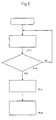
- a portable phone 100 Being turned its power on, a portable phone 100 is set to a standby status. An antenna 102 is kept retracted. Under the standby status, the antenna 102 always receives a receiving control channel sent from a radio base station (not shown).
- the receiving control channel contains a receiving signal and any other information required to give a call.
Landscapes
- Engineering & Computer Science (AREA)
- Computer Networks & Wireless Communication (AREA)
- Signal Processing (AREA)
- Mobile Radio Communication Systems (AREA)
- Transceivers (AREA)
- Support Of Aerials (AREA)
Claims (8)
- Un appareil radio (100) portable comprenant une antenne (102), un récepteur (103), un transmetteur (104), des moyens de détection (105) pour détecter un signal d'appel en réception, et des moyens de commutation de gain (101) réagissant aux moyens de détection (105) pour commuter le gain d'antenne,
caractérisé en ce que lesdits moyens de détection (105) détectent également un signal de transmission émanant dudit transmetteur (104), de manière que les moyens de commutation de gain (101) commutent le gain d'antenne lorsque le signal de transmission a été détecté,
et en ce que les moyens de commutation de gain (101) étendent l'antenne (102) lors de la détection soit du signal de détection, soit du signal de transmission. - Un appareil radio (100) portable selon la revendication 1, dans lequel les moyens de commutation de gain (101) comprennent :des moyens support (127a, 128) pour supporter une extrémité de l'antenne et pour exercer une force sur l'antenne, dans une direction d'extension ;des moyens de commande (122, 124) pour commander ladite force de manière à maintenir ladite antenne (102) en position rétractée ; etdes moyens de libération (125) pour libérer ladite force, lorsque ledit signal d'appel de réception ou ledit signal de transmission a été détecté par lesdits moyens de détection, de manière que ladite antenne soit déployée par l'effet de ladite force.
- Un appareil radio (100) portable selon la revendication 2, dans lequel lesdits moyens support comprennent un organe support (127a) pour supporter une extrémité de l'antenne (102) et un ressort (128) pour exercer une force sur l'antenne, dans une direction d'extension ; lesdits moyens de commande (122, 124) comprenant un verrou (122) pour maintenir l'organe support (127a) en une position à laquelle l'antenne (102) est rétractée ; et lesdits moyens de libération (125) comprenant un électro-aimant (123) devant libérer ledit verrou (122), de manière que ladite antenne (102) soit déployée par l'effet de ladite force.
- Un appareil radio (100) portable selon la revendication 3, dans lequel un deuxième ressort (124) déplace ledit verrou (122) en direction d'une position à laquelle il y a rétention de l'organe support (127a) ; ledit verrou est attiré en direction dudit électro-aimant lorsqu'il est alimenté, à l'encontre de la force exercée par le deuxième ressort (124), de manière que ledit organe support (127a) soit libéré pour déployer l'antenne (102) ; et ledit verrou (122) est rappelé à l'encontre de la force exercée par le deuxième ressort (124), par l'organe support (127a), lorsque l'antenne (102) est rétractée manuellement.
- Un appareil radio (100) portable selon l'une quelconque des revendications précédentes, dans lequel ladite antenne (102) est rétractable manuellement, depuis une position déployée à une position rétractée, et dans lequel lesdits moyens de commutation de gain servent à déployer ladite antenne (102) de la position rétractée à une position intermédiaire, d'où elle est déployable manuellement à ladite position déployée.
- Un appareil radio (100) portable selon l'une quelconque des revendications précédentes, dans lequel lesdits moyens de commutation de gain (101) déploient l'antenne par le relâchement d'un ressort (124) qui provoque la sortie de l'antenne (102) depuis l'intérieur de l'appareil (100), lorsqu'est détecté soit le signal de détection, soit le signal de transmission.
- Un appareil radio (100) portable selon la revendication 6, dans lequel ladite antenne (102) est repoussée pour revenir en prise avec un verrou chargé par ressort (122, 124), pour retenir l'antenne (102) à sa position rétractée.
- Un appareil radio (100) portable selon l'une quelconque des revendications précédentes, ayant un statut d'attente auquel il reçoit de façon continue des émissions radio provenant d'une station de base, se faisant sur un canal de contrôle, et dans lequel lesdits moyens de détection (105) déterminent si un signal reçu contient ou non le signal d'appel en réception pour la station correspondant à l'appareil radio (100) portable.
Applications Claiming Priority (3)
| Application Number | Priority Date | Filing Date | Title |
|---|---|---|---|
| JP6141837A JP2581320B2 (ja) | 1994-06-23 | 1994-06-23 | 携帯型無線装置 |
| JP14183794 | 1994-06-23 | ||
| JP141837/94 | 1994-06-23 |
Publications (3)
| Publication Number | Publication Date |
|---|---|
| EP0689299A2 EP0689299A2 (fr) | 1995-12-27 |
| EP0689299A3 EP0689299A3 (fr) | 1997-05-28 |
| EP0689299B1 true EP0689299B1 (fr) | 2002-09-11 |
Family
ID=15301303
Family Applications (1)
| Application Number | Title | Priority Date | Filing Date |
|---|---|---|---|
| EP95304371A Expired - Lifetime EP0689299B1 (fr) | 1994-06-23 | 1995-06-22 | Procédé pour la commutation du gain d'antenne d'un appareil radio portable |
Country Status (6)
| Country | Link |
|---|---|
| US (1) | US6321099B1 (fr) |
| EP (1) | EP0689299B1 (fr) |
| JP (1) | JP2581320B2 (fr) |
| KR (1) | KR0180324B1 (fr) |
| AU (1) | AU699761B2 (fr) |
| DE (1) | DE69528115T2 (fr) |
Families Citing this family (6)
| Publication number | Priority date | Publication date | Assignee | Title |
|---|---|---|---|---|
| EP0800227A3 (fr) * | 1996-04-02 | 1998-07-08 | Nec Corporation | Dispositif pour commander l'expansion/contraction d'une antenne et méthode pour la commande |
| DE19747581C2 (de) * | 1997-10-28 | 1999-11-25 | Siemens Ag | Mobilfunkendgerät |
| US6507317B1 (en) * | 2000-08-11 | 2003-01-14 | Agere Systems Inc. | Retractable antenna for electronic devices |
| US6573868B2 (en) * | 2001-02-28 | 2003-06-03 | 3Com Corporation | Retractable antenna for electronic devices |
| TWM259325U (en) * | 2004-06-02 | 2005-03-11 | Fih Co Ltd | Automatic antenna |
| US8688174B2 (en) * | 2012-03-13 | 2014-04-01 | Telecommunication Systems, Inc. | Integrated, detachable ear bud device for a wireless phone |
Family Cites Families (20)
| Publication number | Priority date | Publication date | Assignee | Title |
|---|---|---|---|---|
| US3905063A (en) * | 1972-01-07 | 1975-09-16 | Rixson Firemark | Condition responsive door holder-closer |
| US4492820A (en) * | 1980-10-24 | 1985-01-08 | Salt Lake Communications, Inc. | Telephone alarm system |
| EP0193316B1 (fr) * | 1985-02-18 | 1989-09-27 | Nec Corporation | Système de téléphonie mobile pour l'appel automatique d'un abonné mobile absent |
| US4725845A (en) * | 1986-03-03 | 1988-02-16 | Motorola, Inc. | Retractable helical antenna |
| JPS62219719A (ja) * | 1986-03-19 | 1987-09-28 | Matsushita Electric Works Ltd | 送受信装置 |
| US4803493A (en) * | 1986-12-01 | 1989-02-07 | Jamison Wayne L | Mobile antenna circuit with variable line length |
| JPS63185204A (ja) * | 1987-01-28 | 1988-07-30 | Alpine Electron Inc | ラジオ受信機のアンテナ長さ自動調整装置 |
| GB2219159B (en) * | 1988-05-27 | 1993-03-10 | Technophone Ltd | Antenna assembly |
| JPH02252326A (ja) | 1989-03-27 | 1990-10-11 | Nissan Motor Co Ltd | コードレス電話の着信呼出し装置 |
| JPH03235532A (ja) * | 1990-02-13 | 1991-10-21 | Toshiba Corp | コードレス電話装置 |
| JPH03265201A (ja) * | 1990-03-14 | 1991-11-26 | Fujitsu Ltd | アンテナ機構 |
| JPH0439755U (fr) * | 1990-07-31 | 1992-04-03 | ||
| JPH0443032U (fr) * | 1990-08-13 | 1992-04-13 | ||
| JPH0713293Y2 (ja) * | 1991-03-19 | 1995-03-29 | 三洋電機株式会社 | 電子機器のアンテナ装置 |
| JPH0548489A (ja) * | 1991-08-08 | 1993-02-26 | Matsushita Electric Ind Co Ltd | 電話装置 |
| JP2699730B2 (ja) * | 1991-11-27 | 1998-01-19 | 日本電気株式会社 | 携帯無線機のアンテナ取出し機構 |
| JPH05152992A (ja) * | 1991-11-30 | 1993-06-18 | Nec Corp | 無線送受信装置 |
| JP3002985U (ja) * | 1994-02-18 | 1994-10-11 | 株式会社花絹コーポレーション | 携帯電話機 |
| JP3048941U (ja) * | 1997-10-30 | 1998-05-29 | 文長 王 | 揚水ポンプの吐出し口転向装置 |
| JP3121713U (ja) * | 2006-03-06 | 2006-05-25 | 横浜ゴム株式会社 | タイヤ用滑止具 |
-
1994
- 1994-06-23 JP JP6141837A patent/JP2581320B2/ja not_active Expired - Fee Related
-
1995
- 1995-06-13 AU AU21646/95A patent/AU699761B2/en not_active Ceased
- 1995-06-21 KR KR1019950016769A patent/KR0180324B1/ko not_active Expired - Fee Related
- 1995-06-22 DE DE69528115T patent/DE69528115T2/de not_active Expired - Fee Related
- 1995-06-22 EP EP95304371A patent/EP0689299B1/fr not_active Expired - Lifetime
-
1997
- 1997-07-07 US US08/888,528 patent/US6321099B1/en not_active Expired - Fee Related
Also Published As
| Publication number | Publication date |
|---|---|
| AU699761B2 (en) | 1998-12-17 |
| KR960003226A (ko) | 1996-01-26 |
| JPH088776A (ja) | 1996-01-12 |
| EP0689299A3 (fr) | 1997-05-28 |
| DE69528115D1 (de) | 2002-10-17 |
| KR0180324B1 (ko) | 1999-05-15 |
| DE69528115T2 (de) | 2003-01-02 |
| US6321099B1 (en) | 2001-11-20 |
| AU2164695A (en) | 1996-01-11 |
| JP2581320B2 (ja) | 1997-02-12 |
| EP0689299A2 (fr) | 1995-12-27 |
Similar Documents
| Publication | Publication Date | Title |
|---|---|---|
| US5321738A (en) | Switch apparatus of a portable cordless telephone using an antenna | |
| JP3165724B2 (ja) | 通信装置 | |
| US6006117A (en) | Radio telephone with separate antenna for stand-by mode | |
| US5237429A (en) | Facsimile interface device for radios | |
| GB2225512A (en) | Cellular cordless telephone | |
| EP1016157B1 (fr) | Telephone a diverses configurations d'antennes | |
| EP1237289A2 (fr) | Appareil de communication mobil | |
| JP3312735B2 (ja) | 受信機のための聴覚報知器回路 | |
| US20020115455A1 (en) | Extended range cordless telephone system and method | |
| EP0689299B1 (fr) | Procédé pour la commutation du gain d'antenne d'un appareil radio portable | |
| KR920000140B1 (ko) | 무선전화장치용 확성장치와 그 확성방법 | |
| US6035205A (en) | Apparatus and method for enhancing telephone call quality of facsimile system with wireless telephone function | |
| EP1000826A3 (fr) | Dispositif de télécommande pour un véhicule automobile | |
| RU2209515C2 (ru) | Способ управления работой телекоммуникационного терминала, телекоммуникационный терминал и радиомодуль | |
| JPH0621863A (ja) | 無線電話機 | |
| JP2000040988A (ja) | 無線通信装置 | |
| JP3896708B2 (ja) | 無線通信装置 | |
| JPH03182129A (ja) | 移動無線電話システム | |
| JPH06311067A (ja) | 無線電話装置 | |
| JP4588612B2 (ja) | 無線中継システム | |
| KR950007499B1 (ko) | 멀티형 무선전화기 및 그 운용방법 | |
| JPH09172388A (ja) | 自動車電話機 | |
| JPH11274826A (ja) | 携帯無線通話装置 | |
| JP2000196712A (ja) | 移動局とアンテナ装置 | |
| JP3381871B2 (ja) | 携帯無線機 |
Legal Events
| Date | Code | Title | Description |
|---|---|---|---|
| PUAI | Public reference made under article 153(3) epc to a published international application that has entered the european phase |
Free format text: ORIGINAL CODE: 0009012 |
|
| AK | Designated contracting states |
Kind code of ref document: A2 Designated state(s): DE GB IT SE |
|
| PUAL | Search report despatched |
Free format text: ORIGINAL CODE: 0009013 |
|
| AK | Designated contracting states |
Kind code of ref document: A3 Designated state(s): DE GB IT SE |
|
| 17P | Request for examination filed |
Effective date: 19970516 |
|
| 17Q | First examination report despatched |
Effective date: 20000218 |
|
| GRAG | Despatch of communication of intention to grant |
Free format text: ORIGINAL CODE: EPIDOS AGRA |
|
| GRAG | Despatch of communication of intention to grant |
Free format text: ORIGINAL CODE: EPIDOS AGRA |
|
| GRAH | Despatch of communication of intention to grant a patent |
Free format text: ORIGINAL CODE: EPIDOS IGRA |
|
| GRAH | Despatch of communication of intention to grant a patent |
Free format text: ORIGINAL CODE: EPIDOS IGRA |
|
| GRAA | (expected) grant |
Free format text: ORIGINAL CODE: 0009210 |
|
| AK | Designated contracting states |
Kind code of ref document: B1 Designated state(s): DE GB IT SE |
|
| REG | Reference to a national code |
Ref country code: GB Ref legal event code: FG4D |
|
| REF | Corresponds to: |
Ref document number: 69528115 Country of ref document: DE Date of ref document: 20021017 |
|
| PG25 | Lapsed in a contracting state [announced via postgrant information from national office to epo] |
Ref country code: SE Free format text: LAPSE BECAUSE OF FAILURE TO SUBMIT A TRANSLATION OF THE DESCRIPTION OR TO PAY THE FEE WITHIN THE PRESCRIBED TIME-LIMIT Effective date: 20021211 |
|
| PLBE | No opposition filed within time limit |
Free format text: ORIGINAL CODE: 0009261 |
|
| STAA | Information on the status of an ep patent application or granted ep patent |
Free format text: STATUS: NO OPPOSITION FILED WITHIN TIME LIMIT |
|
| 26N | No opposition filed |
Effective date: 20030612 |
|
| PGFP | Annual fee paid to national office [announced via postgrant information from national office to epo] |
Ref country code: GB Payment date: 20040616 Year of fee payment: 10 |
|
| PGFP | Annual fee paid to national office [announced via postgrant information from national office to epo] |
Ref country code: DE Payment date: 20040701 Year of fee payment: 10 |
|
| PG25 | Lapsed in a contracting state [announced via postgrant information from national office to epo] |
Ref country code: IT Free format text: LAPSE BECAUSE OF NON-PAYMENT OF DUE FEES;WARNING: LAPSES OF ITALIAN PATENTS WITH EFFECTIVE DATE BEFORE 2007 MAY HAVE OCCURRED AT ANY TIME BEFORE 2007. THE CORRECT EFFECTIVE DATE MAY BE DIFFERENT FROM THE ONE RECORDED. Effective date: 20050622 Ref country code: GB Free format text: LAPSE BECAUSE OF NON-PAYMENT OF DUE FEES Effective date: 20050622 |
|
| PG25 | Lapsed in a contracting state [announced via postgrant information from national office to epo] |
Ref country code: DE Free format text: LAPSE BECAUSE OF NON-PAYMENT OF DUE FEES Effective date: 20060103 |
|
| GBPC | Gb: european patent ceased through non-payment of renewal fee |
Effective date: 20050622 |