EP0689365A1 - Verteilereinrichtung, insbesondere für den Hauptverteiler von Fernsprech- und Datenleitungen - Google Patents
Verteilereinrichtung, insbesondere für den Hauptverteiler von Fernsprech- und Datenleitungen Download PDFInfo
- Publication number
- EP0689365A1 EP0689365A1 EP95107287A EP95107287A EP0689365A1 EP 0689365 A1 EP0689365 A1 EP 0689365A1 EP 95107287 A EP95107287 A EP 95107287A EP 95107287 A EP95107287 A EP 95107287A EP 0689365 A1 EP0689365 A1 EP 0689365A1
- Authority
- EP
- European Patent Office
- Prior art keywords
- contact
- distribution
- strips
- connection
- distributor
- Prior art date
- Legal status (The legal status is an assumption and is not a legal conclusion. Google has not performed a legal analysis and makes no representation as to the accuracy of the status listed.)
- Granted
Links
- 230000011664 signaling Effects 0.000 claims description 8
- 238000000465 moulding Methods 0.000 abstract 3
- 238000005516 engineering process Methods 0.000 description 4
- 239000007787 solid Substances 0.000 description 4
- 230000005540 biological transmission Effects 0.000 description 2
- 238000006073 displacement reaction Methods 0.000 description 2
- 238000009413 insulation Methods 0.000 description 2
- 238000006243 chemical reaction Methods 0.000 description 1
- 238000010276 construction Methods 0.000 description 1
- 230000002349 favourable effect Effects 0.000 description 1
- 230000006870 function Effects 0.000 description 1
- 238000003780 insertion Methods 0.000 description 1
- 230000037431 insertion Effects 0.000 description 1
- 238000004519 manufacturing process Methods 0.000 description 1
- 230000009993 protective function Effects 0.000 description 1
- 238000009420 retrofitting Methods 0.000 description 1
- 238000000926 separation method Methods 0.000 description 1
- 230000001960 triggered effect Effects 0.000 description 1
Images



Classifications
-
- H—ELECTRICITY
- H01—ELECTRIC ELEMENTS
- H01R—ELECTRICALLY-CONDUCTIVE CONNECTIONS; STRUCTURAL ASSOCIATIONS OF A PLURALITY OF MUTUALLY-INSULATED ELECTRICAL CONNECTING ELEMENTS; COUPLING DEVICES; CURRENT COLLECTORS
- H01R43/00—Apparatus or processes specially adapted for manufacturing, assembling, maintaining, or repairing of line connectors or current collectors or for joining electric conductors
- H01R43/16—Apparatus or processes specially adapted for manufacturing, assembling, maintaining, or repairing of line connectors or current collectors or for joining electric conductors for manufacturing contact members, e.g. by punching and by bending
-
- H—ELECTRICITY
- H04—ELECTRIC COMMUNICATION TECHNIQUE
- H04Q—SELECTING
- H04Q1/00—Details of selecting apparatus or arrangements
- H04Q1/02—Constructional details
- H04Q1/14—Distribution frames
- H04Q1/142—Terminal blocks for distribution frames
-
- H—ELECTRICITY
- H01—ELECTRIC ELEMENTS
- H01R—ELECTRICALLY-CONDUCTIVE CONNECTIONS; STRUCTURAL ASSOCIATIONS OF A PLURALITY OF MUTUALLY-INSULATED ELECTRICAL CONNECTING ELEMENTS; COUPLING DEVICES; CURRENT COLLECTORS
- H01R9/00—Structural associations of a plurality of mutually-insulated electrical connecting elements, e.g. terminal strips or terminal blocks; Terminals or binding posts mounted upon a base or in a case; Bases therefor
- H01R9/22—Bases, e.g. strip, block, panel
- H01R9/24—Terminal blocks
- H01R9/2425—Structural association with built-in components
- H01R9/2441—Structural association with built-in components with built-in overvoltage protection
-
- H—ELECTRICITY
- H04—ELECTRIC COMMUNICATION TECHNIQUE
- H04Q—SELECTING
- H04Q1/00—Details of selecting apparatus or arrangements
- H04Q1/02—Constructional details
- H04Q1/14—Distribution frames
- H04Q1/146—Distribution frames with line protection means
Definitions
- the invention relates to a distribution device, in particular for the main distributor of telephone and data lines according to the preamble of claim 1.
- Such distribution devices serve as an interface for the subscriber and switching centers of telephone systems.
- a distribution device in particular for the main distributor of telephone and data lines, which consists of a plurality of distribution strips with contact elements arranged on the connection side for connecting both the subscriber and the switching cables, from the business service side to the contact elements arranged in the interior of the distributor strips, plugs are formed, and in which contact elements are introduced in the interior of the distributor strips in junction elements arranged next to one another, which form two disconnection points and an intrusion contact on the service side and two intrusion contacts on the rear connection side.
- the contact elements in the interior of each distributor component form a closed line path with a double wire of the switching cable and the subscriber cable, which is manipulated by means of plugs via the openings on the front side of the service center via openings arranged one above the other.
- the invention is therefore based on the object of further developing a distribution device of the generic type so that all operations of the service can be carried out from one side of the frame with the distribution device, the distribution device should be constructed in an uncomplicated manner and require less space.
- the invention provides the characterizing features of claim 1.
- the modular structure of the distributor strips with the contact spring arranged therein in a particularly favorable manner means that less space is required.
- the integrated, complete surge protection concept reduces the number of necessary contact points.
- Full flexibility in switching over the entire network is achieved in particular by using the same components in the entire network.
- the switching means are simpler and therefore more cost-effective to manufacture and assemble.
- With the switching means designed according to the invention the performance of the interfaces to the network is increased.
- the existing technology can also be used better than before.
- the entire wiring is done by plugging. Changes can be made quickly and economically.
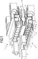
- the distributor device 1 shown in simplified form in FIG. 1 comprises distributor strips 2 with distributor components 3 with openings 4, 5, 34 on the service side 6, with contact springs 7 inside and with slots 8 on the connection side 9 for receiving the wires of an incoming cable (not shown) ), e.g. a system cable, and connector 10 for protection, connector 11 for disconnecting and connecting line paths and a central part 12 with contact elements 13 for forming a second disconnection point.
- an incoming cable not shown
- the distribution device 1 here consists of two distribution strips 2, slightly offset one above the other, and the middle part 12 arranged therebetween.
- the top strip 2 is snapped onto the middle part 12 by 180 degrees to the bottom strip 2.
- Each distribution strip 2 consists of 8 distribution components 3 for eight double wires.
- Fig. 2 shows a perspective view of a distribution strip 2 for eight pairs, as they can be used to terminate cables in the main distributor, but also in cable distributors and in transmission technology.
- the distributor device 1 is constructed modularly from these distributor strips 2.
- the distribution devices 1 are preferably constructed from distribution strips 2 with a connection capacity of eight pairs each. However, four twin-wire units can also be implemented.
- the distributor strip 2 consists of a housing part 14 with locking devices 15 for snapping onto a frame formed from round rods (not shown) and with rows of slots 8 for receiving cable wires and with connecting elements 17, 18 for lining up strips 2 in a horizontal and vertical sequence.
- Each distribution strip 2 is constructed in the manner of a plug and can be used as such in the cable network or in the switching system. This means that changes can be made to the cable network or in switching systems by changing the plug. Switching and rearranging becomes unnecessary.
- Each cable terminated with the distribution device 1 according to FIG. 1 can be quickly plugged into any transmission technology device.
- the individual cable cores are terminated with connection contacts 19, for example insulation displacement contact elements (not shown) on the connection side 9 of the distributor strips 2.
- a one-piece contact spring 7 is introduced into the distribution strip 2 per wire, via which all protection and switching functions are implemented.
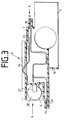
- FIG. 3 shows the arrangement of the contact spring 7 in a cross section through the distributor strip 2 according to FIG. 2.
- the contact spring 7 is designed in one piece as shown in FIG. 4.
- an insulation displacement terminal is formed as a connection contact 19 for the closed cable (not shown), from the base 20 of which a contact spring 22, which is slotted in the middle and front region 21, is bent out to form a telecommunication contact.
- the Contact spring 22 for forming the remote signaling contact is slotted to achieve a double contact and thus double security.
- the remote signaling contact to be formed from the contact spring 22 (see FIG. 5) can be designed as a switching or isolating contact 31, 32.
- the contact spring 22 is bent in part of its slotted area so that it protrudes from the housing part 14 (Fig. 1, 2).
- the legs 23 created by the free cutting of the contact spring 22 from the center of the base 20 of the connection contact 19 are bent in a U-shape, the bases 24 of the legs 23 being supported on the housing part 14 (FIG. 2).
- the length of the legs 23 corresponds to the length of the free cut of the contact spring 22.
- the legs 23 end just below a solid surface 25, which is formed parallel to the connection contact 19.
- a second connection contact 26 is formed from the solid surface 25 on the service side 6 by free cutting and angling for the connection of possibly necessary jumper wires. After the vertical bend from the plane of the solid surface 25, the second connection contact 26 is again parallel to the solid surface 25 and to the first connection contact 19 and lies on the housing part 14 (FIG. 2). The remaining rest of the full surface 25 is again cut free in the front region and bent into a contact surface 27 at a 90 ° angle to the full surface 25.
- the contact surface 27 serves to make contact with a surge arrester 28 (FIG. 1).
- the contact spring 7 is as shown in 3 so introduced into the distributor component 3 that the connection contact 19 for closed cables via the slot 8 on the connection side 9, the connection contact 26 for the possible connection of a jumper wire via the slot 34 and the contact surface 27 for contacting the surge arrester 28 via the opening 4 can be reached.
- the contact spring 22 provided for forming the telecommunication contact is accessible via an opening 29 in the housing part 14 of the distributor strip 2.
- the middle part 12 shows the design and application of the middle part 12. If the user desires overvoltage protection or 5-point protection, it is possible to insert the middle part 12 between two distribution strips 2. As a result, a second separation point is generated via the contact element 13 and is used for grinding in securing elements.
- the overvoltage protection can be installed separately from the coarse protection. Furthermore, there is a possibility through contacts in the central part 12 of electrically reporting the status of the triggered fail-safe to the outside. A restriction of the handling on the distribution device 1 does not occur due to the protection that is plugged in.
- the surge arrester 28 is fully integrated in the distribution strips 2. After the insertion of earth rails 30 (FIG. 1) into the distribution strip 2, only the surge arrester 28 needs to be used for the respective double wires, which leads the line path via the contact surface 27 of the contact spring 7 closes in the event of an error.
- the surge arrester 28 remains accessible from the front at all times, even during operation, so that any fail-safe that may be used also shows the status of the respective double wire from the front.
- side-by-side distribution strips 2 are shown.
- the distribution strips 2 can be strung together to form 16 DA or 24 DA strips.
- Higher-pair cables are intercepted on the frame, not shown, and divided into the number of double wires corresponding to the strips 2.
- the termination units of a cable assembled in this way can then be plugged together with the same units of another cable or device.
- the remote signaling contact is formed by the two modules, as shown in FIG. 5.
- the telecommunications contact is formed from the central regions 21 of the contact springs 22 of the distributor strips 2 arranged one above the other.
- the remote signaling contact switches each wire 1: 1.
- the strips 2 can be plugged together in two different latching positions, so that either an isolating or switching contact 32, 31 is formed. Switching from one operating mode to the other can also be carried out reversibly at any time during operation.
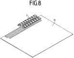
- FIG. 8 shows a supplementary embodiment.
- the distributor strip 2 is provided for contacting printed circuit boards.
- a circuit board 33 is inserted instead of the cable connection.
- the distribution strip 2 serves here as an interface between active technology and the incoming cables. The device can only be started up by plugging in the cable. There is also the possibility of testing and disconnection, maneuverability, and the possibility of surge protection.
- the distributor strips 2 are fastened in their combination as a distributor device 1 to a frame in vertical bays.
- the distribution strips 2 are preferably used as 16 DA units.
- the distribution strips 2 for terminating the system cables are plugged together with those on the subscriber side. This creates a 1: 1 connection of the subscriber to the system cables without routing.
- the retrofitting or repositioning of distribution strips 2 is also possible at any time during operation.
- Each vertical bay can hold up to 50 of these 16 connected DA units. This results in a much higher capacity of interconnected twisted pairs than before.
- the proportion of routable lines can be up to 100%.
- a "classic" distribution distributor can also be set up if the environment of the main distributor for the modern network structure is not yet available. The conversion to a manipulation distributor with 1: 1 switching can then be done again by repositioning the existing cable terminations.
Landscapes
- Engineering & Computer Science (AREA)
- Manufacturing & Machinery (AREA)
- Computer Networks & Wireless Communication (AREA)
- Structure Of Telephone Exchanges (AREA)
- Coupling Device And Connection With Printed Circuit (AREA)
- Time-Division Multiplex Systems (AREA)
- Radio Relay Systems (AREA)
- Sub-Exchange Stations And Push- Button Telephones (AREA)
- Telephonic Communication Services (AREA)
Abstract
Description
- Die Erfindung bezieht sich auf eine Verteilereinrichtung, insbesondere für den Hauptverteiler von Fernsprech- und Datenleitungen gemäß dem Oberbegriff des Anspruches 1.
- Derartige Verteilereinrichtungen, insbesondere für den Hauptverteiler von Fernsprechanlagen, dienen als Schnittstelle für die Teilnehmer- und Vermittlungsstellen von Fernsprechanlagen.
- Aus der DE 43 06 349 C1 ist eine Verteilereinrichtung, insbesondere für den Hauptverteiler von Fernsprech- und Datenleitungen bekannt, der aus einer Mehrzahl von Verteilerleisten mit auf der Anschlußseite angeordneten Kontaktelementen zum Anschluß sowohl der Teilnehmer- als auch der Vermittlungskabel, mit von der Betriebsdienstseite her an die im Inneren der Verteilerleisten angeordneten Kontaktelemente anschließbaren Steckern, gebildet ist und bei der im Inneren der Verteilerleisten in nebeneinander angeordneten Verteilerbauelementen Kontaktelemente eingebracht sind, die zwei Trennstellen und einen Aufschaltekontakt auf der Betriebsdienstseite und zwei Aufschaltekontakte auf der rückwärtigen Anschlußseite bilden. Die Kontaktelemente im Inneren jedes Verteilerbauelementes bilden mit einer Doppelader des Vermittlungskabels und des Teilnehmerkabels einen geschlossenen Leitungsweg, welcher über die vorne liegende Betriebsdienstseite über übereinander angeordnete Öffnungen mittels Stecker manipuliert wird.
- Nachteilig ist es bei dieser Verteilereinrichtung, daß eine komplizierte Kontaktgestaltung mit vielen Einzelteilen die Ausbildung des Schaltmittels erschwert. Darüber hinaus muß auch jede Rangier- und Schutzfunktion durch Stecker realisiert werden.
- Der Erfindung liegt von daher die Aufgabe zugrunde, eine Verteilereinrichtung der gattungsgemäßen Art so weiterzubilden, daß alle Arbeiten des Betriebsdienstes von einer Seite des Gestelles mit der Verteilereinrichtung erledigt werden können, wobei die Verteilereinrichtung unkompliziert aufgebaut sein soll und einen geringeren Platzbedarf erfordert.
- Zur Lösung dieser Aufgabe sieht die Erfindung die kennzeichnenden Merkmale des Anspruches 1 vor. Durch den modularen Aufbau der Verteilerleisten mit der darin angeordneten in besonders günstiger Weise ausgestalteten Kontaktfeder wird ein geringerer Platzbedarf erreicht. Das integrierte vollständige Überspannungsschutz-Konzept verringert die Anzahl der notwendigen Kontaktstellen. Es wird eine volle Flexibilität bei Umschaltungen im gesamten Netz insbesondere auch durch die Benutzung der gleichen Bauteile im gesamten Leitungsnetz erreicht. Die Schaltmittel sind einfacher und damit kostengünstiger in der Herstellung und bei der Montage gestaltet. Mit dem erfindungsgemäß konzipierten Schaltmittel wird die Leistungsfähigkeit der Schnittstellen zum Netz erhöht. Auch die vorhandene Technik kann besser als bisher genutzt werden. Die gesamte Verkabelung erfolgt durch Stecken. Änderungen sind schnell und wirtschaftlich durchführbar.
- Die Erfindung ist nachfolgend anhand eines in den Zeichnungen dargestellten Ausführungsbeispieles einer Verteilereinrichtung näher erläutert. Es zeigen:
- Fig. 1
- eine perspektivische Prinzipdarstellung einer Verteilereinrichtung,
- Fig. 2
- eine perspektivische Darstellung einer Verteilerleiste in der Verteilereinrichtung nach Fig. 1,
- Fig. 3
- einen Schnitt durch die Verteilerleiste nach Fig. 2,
- Fig. 4
- eine perspektivische Darstellung der Kontaktfeder, wie sie in der Verteilerleiste gemäß der Figuren 2 und 3 verwendet ist,
- Fig. 5
- eine Schnittdarstellung durch mehrere übereinander gesteckte Verteilerleisten nach Fig. 2 mit Fernmeldekontakten als Trenn-/Schaltkontakt ausgebildet,
- Fig. 6
- eine perspektivische Darstellung seitlich aneinander reihbarer Verteilerleisten,
- Fig. 7
- eine perspektivische Darstellung von seitlich und übereiandergereihten Verteilerleisten mit Rangierdrähten und
- Fig. 8
- eine perspektivische Darstellung der Verbindung einer Verteilerleiste mit einer Leiterplatte.
- Die in Fig. 1 vereinfacht dargestellte Verteilereinrichtung 1 umfaßt Verteilerleisten 2 mit Verteilerbauelementen 3 mit Öffnungen 4,5,34 auf der Betriebsdienstseite 6, mit Kontaktfedern 7 im Inneren und mit Schlitzen 8 auf der Anschlußseite 9 zur Aufnahme der Adern eines ankommenden Kabels (nicht dargestellt), z.B. einem Systemkabel, sowie Stecker 10 zum Schützen, Stecker 11 zum Trennen und zum Aufschalten von Leitungswegen und ein Mittelteil 12 mit Kontaktelementen 13 zur Bildung einer zweiten Trennstelle. Jeder Leitungsweg, gebildet aus einer Doppelader, ist dabei einzeln schützbar. Die Verteilereinrichtung 1 besteht hier aus zwei übereinander leicht versetzt liegenden Verteilerleisten 2 und dem dazwischen angeordneten Mittelteil 12. Die oben liegende Leiste 2 ist dabei um 180 Grad zur unten liegenden Leiste 2 auf das Mittelteil 12 aufgerastet. Jede Verteilerleiste 2 besteht aus 8 Verteilerbauelementen 3 für acht Doppeladern.
- Die Fig. 2 zeigt in perspektivischer Ansicht eine Verteilerleiste 2 für acht Doppeladern, wie sie zum Abschluß von Kabeln im Hauptverteiler, aber auch in Kabelverzweigern und in der Übertragungstechnik verwendbar sind. Die Verteilereinrichtung 1 ist modular aus diesen Verteilerleisten 2 aufgebaut. Vorzugsweise sind die Verteilereinrichtungen 1 aus Verteilerleisten 2 mit einer Anschaltekapazität von jeweils acht Doppeladern aufgebaut. Es sind jedoch auch vier Doppelader-Einheiten realisierbar.
- Die Verteilerleiste 2 besteht aus einem Gehäuseteil 14 mit Rastvorrichtungen 15 zum Aufrasten auf einen aus Rundstangen gebildeten Rahmen (nicht dargestellt) sowie mit Reihen von Schlitzen 8 zur Aufnahme von Kabeladern und mit Verbindungselementen 17,18 zum Aneinanderreihen von Leisten 2 in waagerechter und senkrechter Folge. Jede Verteilerleiste 2 ist in der Art eines Steckers aufgebaut und kann als solcher im Kabelnetz oder im Vermittlungssystem benutzt werden. Dadurch können am Kabelnetz oder in Vermittlungssystemen Änderungen durch Umstecken vorgenommen werden. Das Neubeschalten und Umrangieren wird unnötig. Jedes mit der Verteilereinrichtung 1 nach Fig. 1 abgeschlossene Kabel kann schnell an jedes beliebige Gerät der Übertragungstechnik angesteckt werden. Die einzelnen Kabeladern werden mit Anschlußkontakten 19, z.B. Schneid-Klemm-Kontaktelementen (nicht dargestellt) auf der Anschlußseite 9 der Verteilerleisten 2 abgeschlossen. In der Verteilerleiste 2 ist pro Ader eine einteilige Kontaktfeder 7 eingebracht, über die sämtliche Schutz- und Schaltfunktionen realisiert werden.
- In der Fig. 3 ist in einem Querschnitt durch die Verteilerleiste 2 nach Fig. 2 die Anordnung der Kontaktfeder 7 gezeigt. Die Kontaktfeder 7 ist entsprechend der Darstellung in der Fig. 4 einstückig ausgeführt. Auf der Anschlußseite 9 ist eine Schneidklemme als Anschlußkontakt 19 für das abgeschlossene Kabel (nicht dargestellt) ausgebildet, aus deren Basis 20 eine im mittleren und vorderen Bereich 21 geschlitzte Kontaktfeder 22 zur Ausbildung eines Fernmeldekontaktes herausgebogen ist. Die Kontaktfeder 22 zur Bildung des Fernmeldekontaktes ist geschlitzt ausgeführt, um einen Doppelkontakt und damit eine doppelte Sicherheit zu erreichen. Der aus der Kontaktfeder 22 zu bildende Fernmeldekontakt (siehe Fig. 5) kann als Schalt- oder Trennkontakt 31,32 ausgebildet sein. Die Kontaktfeder 22 ist in einem Teil ihres geschlitzten Bereiches so gebogen, daß sie aus dem Gehäuseteil 14 (Fig.1,2) herausragt. Die durch den Freischnitt der Kontaktfeder 22 aus der Mitte der Basis 20 des Anschlußkontaktes 19 entstandenen Schenkel 23 sind U-förmig abgebogen, wobei die Basen 24 der Schenkel 23 sich am Gehäuseteil 14 abstützen (Fig.2). Die Länge der Schenkel 23 entspricht der Länge des Freischnitts der Kontaktfeder 22. Die Schenkel 23 enden kurz unterhalb einer Vollfläche 25, die parallel zum Anschlußkontakt 19 gebildet ist. Aus der Vollfläche 25 ist auf der Betriebsdienstseite 6 ein zweiter Anschlußkontakt 26 durch Freischnitt und Abwinkelung für den Anschluß eventuell erforderlicher Rangierdrähte herausgeformt. Der zweite Anschlußkontakt 26 liegt nach der senkrechten Abwinkelung aus der Ebene der Vollfläche 25 wiederum parallel zur Vollfläche 25 und zum ersten Anschlußkontakt 19 und liegt auf dem Gehäuseteil 14 auf (Fig.2). Der verbleibende Rest der Vollfläche 25 ist im vorderen Bereich wiederum freigeschnitten und zu einer Kontaktfläche 27 in 90°-Abwinkelung zur Vollfläche 25 gebogen. Die Kontaktfläche 27 dient zur Kontaktierung mit einem Überspannungsableiter 28 (Fig.1).
- Die Kontaktfeder 7 ist entsprechend der Darstellung in der Fig. 3 so in das Verteilerbauelement 3 eingebracht, daß der Anschlußkontakt 19 für abgeschlossene Kabel über den Schlitz 8 auf der Anschlußseite 9, der Anschlußkontakt 26 für den eventuellen Anschluß eines Rangierdrahtes über den Schlitz 34 und die Kontaktfläche 27 zum Kontaktieren der Überspannungsableiter 28 über die Öffnung 4 erreichbar ist. Die zur Bildung des Fernmeldekontaktes vorgesehene Kontaktfeder 22 ist über eine Öffnung 29 im Gehäuseteil 14 der Verteilerleiste 2 zugänglich.
- Die Fig. 1 zeigt die Ausbildung und Anwendung des Mittelteils 12. Wird vom Anwender ein Überspannungsfeinschutz oder ein 5-Punkte-Schutz gewünscht, so besteht die Möglichkeit, zwischen zwei Verteilerleisten 2 das Mittelteil 12 einzufügen. Dadurch wird über das Kontaktelement 13 eine zweite Trennstelle erzeugt, die zum Einschleifen von Sicherungselementen dient. Der Überspannungsfeinschutz kann getrennt vom Grobschutz installiert werden. Weiterhin ist durch Kontaktierungen im Mittelteil 12 eine Möglichkeit gegeben, den Zustand des ausgelösten Fail-Safes elektrisch nach außen zu melden. Eine Einschränkung des Handlings an der Verteilereinrichtung 1 tritt durch den gesteckten Schutz nicht auf.
- Der Überspannungsableiter 28 ist voll in die Verteilerleisten 2 integriert. Nach dem Einsetzen von Erdschienen 30 (Fig.1) in die Verteilerleiste 2 braucht nur noch der Überspannungsableiter 28 für die jeweiligen Doppeladern eingesetzt zu werden, der über die Kontaktfläche 27 der Kontaktfeder 7 den Leitungsweg im Fehlerfall schließt. Der Überspannungsableiter 28 bleibt auch im Betrieb jederzeit von vorne zugängig, so daß auch ein eventuell verwendeter Fail-Safe von vorne sichtbar den Zustand der jeweiligen Doppelader anzeigt.
- In der Fig. 6 sind seitlich aneinanderreihbare Verteilerleisten 2 gezeigt. Um möglichst flexibel die unterschiedlichen Kabel abschließen zu können, sind die Verteilerleisten 2 seitlich zu 16 DA- oder 24 DA-Leisten aneinander reihbar. Höherpaarige Kabel werden am nicht dargestellten Gestell abgefangen und in die den Leisten 2 entsprechende Anzahl von Doppeladern aufgeteilt. Die so zusammengestellten Abschlußeinheiten eines Kabels können dann mit den gleichen Einheiten eines anderen Kabels oder Gerätes zusammengesteckt werden. Dabei wird durch beide Baugruppen der Fernmeldekontakt entsprechend der Darstellung in der Fig. 5 gebildet. Der Fernmeldekontakt wird aus den mittleren Bereichen 21 der Kontaktfedern 22 der übereinander angeordneten Verteilerleisten 2 gebildet. Der Fernmeldekontakt schaltet jede Ader 1:1 durch. Das Zusammenstecken der Leisten 2 kann in zwei verschiedenen Raststellungen erfolgen, so daß wahlweise ein Trenn- oder Schaltkontakt 32,31 entsteht. Das Umschalten von einer Betriebsart auf die andere kann auch im Betrieb jederzeit reversibel durchgeführt werden.
- Ist in Ausnahmefällen eine Rangierung von einzelnen Doppeladern nötig, kann durch Stecken eines Trennsteckers 11 und Anschalten eines Rangierdrahtes 35 entsprechend der Darstellung in der Fig. 7 an den vorderen Anschlußkontakt 26 eine Verbindung hergestellt werden, die von der 1:1-Durchschaltung der Leiste 2 abweicht. Die Verteilerleisten 2 bieten die Möglichkeit, bis zu 100 % der angeschalteten Doppeladern zu rangieren.
- Eine ergänzende Ausführungsform zeigt die Figur 8. In der dargestellten Variante ist die Verteilerleiste 2 zum Kontaktieren von Leiterplatten vorgesehen. Auf der Anschlußseite 9 der Verteilerleiste 2 wird anstelle der Kabelanschaltung eine Leiterplatte 33 eingesteckt. Die Verteilerleiste 2 dient hier als Schnittstelle von aktiver Technik zu den ankommenden Kabeln. Eine Inbetriebnahme des Gerätes erfolgt nur noch durch Anstecken des Kabels. Es besteht auch hier die Prüf- und Trennmöglichkeit, die Rangierbarkeit, die Möglichkeit des Überspannungsschutzes.
- Bei einem Aufbau als Hauptverteiler werden die Verteilerleisten 2 in ihrer Kombination als Verteilereinrichtung 1 an einem Gestell in senkrechten Buchten befestigt. Die Verteilerleisten 2 werden dabei vorzugsweise als 16 DA-Einheiten verwendet. Die Verteilerleisten 2 zum Kabelabschluß der Systemkabel werden mit denen auf der Teilnehmerseite zusammengesteckt. Dadurch wird ohne zu rangieren, eine 1:1-Verbindung der Teilnehmer- zu den Systemkabeln hergestellt. Das Nachrüsten oder das Umstecken von Verteilerleisten 2 ist auch nachträglich im Betrieb jederzeit möglich.
- Jede senkrechte Bucht kann bis zu 50 Stück dieser durchgeschalteten 16 DA-Einheiten aufnehmen. Somit ergibt sich ein wesentlich höheres Fassungsvermögen von durchgeschalteten Doppeladern als bisher.
- Der Anteil an rangierbaren Leitungen kann bis zu 100 % betragen. Es kann also auch ein "klassischer" Rangierverteiler aufgebaut werden, wenn das Umfeld des Hauptverteilers für den modernen Netzaufbau noch nicht vorhanden ist. Der Umbau zu einem Manipulierverteiler mit 1:1-Durchschaltung kann dann auch wieder durch Umstecken der vorhandenen Kabelabschlüsse erfolgen.
- Im Kabelverzweiger können die gleichen Verteilerleisten 2 mit den beschriebenen Vorteilen verwendet werden.
Claims (5)
- Verteilereinrichtung, insbesondere für den Hauptverteiler von Fernsprech- und Datenleitungen, aus einer Mehrzahl von Verteilerleisten mit auf der Anschlußseite angeordneten Kontaktelementen zum Anschluß sowohl der Teilnehmer- als auch der Vermittlungskabel, mit von der Betriebsdienstseite her an die im Inneren der Verteilerleisten angeordneten Kontaktelemente anschließbaren Steckern,
dadurch gekennzeichnet, daß
die modular aufgebauten Verteilerleisten (2) Kabelabschlußmodule mit integriertem Überspannungsschutz bilden und daß die Kontaktelemente im Inneren der Verteilerleisten (2) aus einer einstückigen Kontaktfeder (7) mit einem Anschlußkontakt (19) auf der Anschlußseite (9), mit einem weiteren Anschlußkontakt (26) auf der Betriebsdienstseite (6), mit einem Fernmeldekontakt (22) im mittleren Bereich (21) und aus einer Kontaktfläche (27) zur Kontaktierung mit einem Überspannungsschutz (28) gebildet sind. - Verteilereinrichtung nach Anspruch 1, dadurch gekennzeichnet, daß jeweils zwei Verteilerleisten (2) aufeinandergerastet einen Fernmeldekontakt (22) bilden.
- Verteilereinrichtung nach Anspruch 2, dadurch gekennzeichnet, daß durch verschiedene Raststellungen von jeweils zwei Verteilerleisten (2) zueinander, im Betriebsdienst eine Umschaltmöglichkeit des Fernmeldekontaktes (22) von Trennkontakt (32) auf Schaltkontakt (31) und umgekehrt gegeben ist.
- Verteilereinrichtung nach Anspruch 1, dadurch gekennzeichnet, daß die Verteilerleisten (2) jeweils über ein Mittelteil (12) übereinandergerastet sind, wobei das Mittelteil (12) ein aus dem Mittelteilgehäuse heraus nach oben und unten herausgeformtes Kontaktelement (13) aufweist, welches mit den jeweiligen Fernmeldekontakten (22) zu einer weiteren Trennstelle kontaktiert.
- Verteilereinrichtung nach Anspruch 1, dadurch gekennzeichnet, daß die Verteilerleisten (2) seitlich aneinanderreihbar sind, wobei die eingebrachten Erdschienen (30) miteinander verbunden sind.
Applications Claiming Priority (2)
| Application Number | Priority Date | Filing Date | Title |
|---|---|---|---|
| DE4423339A DE4423339C1 (de) | 1994-06-20 | 1994-06-20 | Verteilereinrichtung, insbesondere für den Hauptverteiler von Fernsprech- und Datenleitungen |
| DE4423339 | 1994-06-20 |
Publications (2)
| Publication Number | Publication Date |
|---|---|
| EP0689365A1 true EP0689365A1 (de) | 1995-12-27 |
| EP0689365B1 EP0689365B1 (de) | 2001-01-24 |
Family
ID=6522171
Family Applications (1)
| Application Number | Title | Priority Date | Filing Date |
|---|---|---|---|
| EP95107287A Expired - Lifetime EP0689365B1 (de) | 1994-06-20 | 1995-05-13 | Verteilereinrichtung, insbesondere für den Hauptverteiler von Fernsprech- und Datenleitungen |
Country Status (6)
| Country | Link |
|---|---|
| EP (1) | EP0689365B1 (de) |
| AT (1) | ATE198970T1 (de) |
| DE (2) | DE4423339C1 (de) |
| DK (1) | DK0689365T3 (de) |
| ES (1) | ES2154306T3 (de) |
| GR (1) | GR3035763T3 (de) |
Cited By (3)
| Publication number | Priority date | Publication date | Assignee | Title |
|---|---|---|---|---|
| US6821153B2 (en) | 1999-11-29 | 2004-11-23 | Quante Ag | Overvoltage protection magazine |
| EP1699117A1 (de) * | 2005-03-04 | 2006-09-06 | 3M Innovative Properties Company | Telekommunikationsmodul, Anordnung von Telekommunikationsmodulen und mindestens ein externes Modul, Verfahren zur Herstellung eines Telekommunikationsmoduls und Gebrauch eines Telekommunikationsmoduls |
| US8025523B2 (en) | 2007-06-05 | 2011-09-27 | Adc Gmbh | Plug-in connector for a printed circuit board |
Families Citing this family (11)
| Publication number | Priority date | Publication date | Assignee | Title |
|---|---|---|---|---|
| IN190215B (de) * | 1995-09-26 | 2003-07-05 | Siemens Ag | |
| EP0766482A3 (de) * | 1995-09-29 | 2000-02-02 | KRONE Aktiengesellschaft | Verteilereinrichtung für die Telekommunikations- und Datentechnik |
| US6398580B2 (en) * | 2000-01-11 | 2002-06-04 | Visteon Global Tech., Inc. | Electrical terminal member |
| DE20108245U1 (de) | 2001-05-16 | 2001-07-26 | Schiederwerk MBZ Telekommunikation GmbH & Co., 90451 Nürnberg | Telekommunikation-Endverzweiger mit Prüfabschlüssen |
| DE102007026096A1 (de) | 2007-06-05 | 2008-12-11 | Adc Gmbh | Aderanschlussmodul |
| DE102007026097B4 (de) | 2007-06-05 | 2023-05-11 | Tyco Electronics Services Gmbh | Steckverbinder für Leiterplatten |
| DE102007026094B4 (de) | 2007-06-05 | 2023-05-11 | Tyco Electronics Services Gmbh | Kontaktelement für einen Steckverbinder für Leiterplatten |
| DE102007026095A1 (de) | 2007-06-05 | 2008-12-11 | Adc Gmbh | Erdkamm, insbesondere für einen Steckverbinder für Leiterplatten |
| DE202011003533U1 (de) * | 2011-03-04 | 2011-10-21 | Ccs Technology, Inc. | Kontaktfeder einer Verteilereinrichtung einer Telekommunikationsanlage |
| DE102011016063A1 (de) * | 2011-04-05 | 2012-10-11 | Adc Gmbh | Verteileranschlussmodul |
| DE102012214516A1 (de) * | 2012-06-19 | 2013-12-19 | Tyco Electronics Amp Gmbh | Verteileranschlussmodul |
Citations (3)
| Publication number | Priority date | Publication date | Assignee | Title |
|---|---|---|---|---|
| EP0518390A2 (de) * | 1985-07-15 | 1992-12-16 | AT&T Corp. | Steckbuchse und Prüfstecker |
| EP0576318A1 (de) * | 1992-06-18 | 1993-12-29 | Ingenierie Boga | Matrixverteiler, Leiterplatte und Verfahren zur Verteilerverwaltung |
| EP0624043A1 (de) * | 1993-05-03 | 1994-11-09 | The Whitaker Corporation | Kabelverwaltungssystem |
Family Cites Families (3)
| Publication number | Priority date | Publication date | Assignee | Title |
|---|---|---|---|---|
| DE3921228A1 (de) * | 1989-06-28 | 1991-01-10 | Siemens Ag | Verteilerleiste fuer telekommunikationsanlagen |
| DE4114947C1 (en) * | 1991-05-07 | 1992-08-20 | Siemens Ag, 8000 Muenchen, De | Protective plug for coupling to distributor contact module - has two differently shaped contact faces for contact spring of spring pair |
| DE4306349C1 (de) * | 1993-02-23 | 1994-03-17 | Krone Ag | Verteilereinrichtung, insbesondere für den Hauptverteiler von Fernsprech- und Datenleitungen |
-
1994
- 1994-06-20 DE DE4423339A patent/DE4423339C1/de not_active Expired - Fee Related
-
1995
- 1995-05-13 DK DK95107287T patent/DK0689365T3/da active
- 1995-05-13 ES ES95107287T patent/ES2154306T3/es not_active Expired - Lifetime
- 1995-05-13 AT AT95107287T patent/ATE198970T1/de not_active IP Right Cessation
- 1995-05-13 EP EP95107287A patent/EP0689365B1/de not_active Expired - Lifetime
- 1995-05-13 DE DE59508987T patent/DE59508987D1/de not_active Expired - Fee Related
-
2001
- 2001-04-19 GR GR20010400611T patent/GR3035763T3/el not_active IP Right Cessation
Patent Citations (3)
| Publication number | Priority date | Publication date | Assignee | Title |
|---|---|---|---|---|
| EP0518390A2 (de) * | 1985-07-15 | 1992-12-16 | AT&T Corp. | Steckbuchse und Prüfstecker |
| EP0576318A1 (de) * | 1992-06-18 | 1993-12-29 | Ingenierie Boga | Matrixverteiler, Leiterplatte und Verfahren zur Verteilerverwaltung |
| EP0624043A1 (de) * | 1993-05-03 | 1994-11-09 | The Whitaker Corporation | Kabelverwaltungssystem |
Cited By (3)
| Publication number | Priority date | Publication date | Assignee | Title |
|---|---|---|---|---|
| US6821153B2 (en) | 1999-11-29 | 2004-11-23 | Quante Ag | Overvoltage protection magazine |
| EP1699117A1 (de) * | 2005-03-04 | 2006-09-06 | 3M Innovative Properties Company | Telekommunikationsmodul, Anordnung von Telekommunikationsmodulen und mindestens ein externes Modul, Verfahren zur Herstellung eines Telekommunikationsmoduls und Gebrauch eines Telekommunikationsmoduls |
| US8025523B2 (en) | 2007-06-05 | 2011-09-27 | Adc Gmbh | Plug-in connector for a printed circuit board |
Also Published As
| Publication number | Publication date |
|---|---|
| ES2154306T3 (es) | 2001-04-01 |
| EP0689365B1 (de) | 2001-01-24 |
| ATE198970T1 (de) | 2001-02-15 |
| DE59508987D1 (de) | 2001-03-01 |
| DK0689365T3 (da) | 2001-03-05 |
| GR3035763T3 (en) | 2001-07-31 |
| DE4423339C1 (de) | 1995-09-21 |
Similar Documents
| Publication | Publication Date | Title |
|---|---|---|
| DE69305524T2 (de) | Verbessertes durchgangs-stecker-system für telekommunikations-systeme | |
| DE69839082T2 (de) | XDSL Trennvorrichtung für Hauptverteiler | |
| EP0388585B1 (de) | Schutzstecker für Anschlussleisten der Fernmelde- und Datentechnik | |
| EP1527503B1 (de) | Verteileranschlussmodul für die telekommunikations- und datentechnik | |
| DE4423339C1 (de) | Verteilereinrichtung, insbesondere für den Hauptverteiler von Fernsprech- und Datenleitungen | |
| EP0766482A2 (de) | Verteilereinrichtung für die Telekommunikations- und Datentechnik | |
| EP0243296B1 (de) | Verteilereinrichtung, insbesondere für den Hauptverteiler von Fernsprechanlagen | |
| DE2706681A1 (de) | Schutzeinrichtung fuer niederspannungsleitungen, insbesondere fuer fernsprechnetze | |
| EP0364658A2 (de) | Verteilereinrichtung, insbesondere für den Hauptverteiler von Fernsprechanlagen | |
| DE20200746U1 (de) | Anschlussblock und Verteilereinrichtung mit einem Anschlussblock | |
| DE19608517C1 (de) | Anschlußmodul für die Telekommunikationstechnik | |
| EP1922791A1 (de) | Schutzstecker für ein anschlussmodul | |
| EP1117158B1 (de) | Vorrichtung zur Schirmung für Anschlussleisten | |
| DE19537529C1 (de) | Verteilerleiste für die Telekommunikations- und Datentechnik | |
| EP0121223A1 (de) | Verteilerleiste mit einer Mehrzahl von den abisolierfreien Anschluss elektrischer Leiter gestattenden Doppelanschlussklemmen | |
| DE4042240C2 (de) | Anschlußmodul für eine Verteilereinrichtung, insbesondere für den Hauptverteiler von Fernmeldeeinrichtungen | |
| EP0414043B1 (de) | Verteilerleiste für eine Telekommunkationsanlage | |
| EP0365780B1 (de) | Anschlussvorrichtung zum Schalten oder Trennen von Leitungswegen in Fernsprechvermittlungsanlagen | |
| DE2642779B1 (de) | Mehrpoliger rangierstecker | |
| DE29515983U1 (de) | Montagebügel | |
| EP0121221B1 (de) | Rangierleiste mit einer Mehrzahl von den abisolierfreien Anschluss elektrischer Leiter gestattenden Doppelanschlussklemmen | |
| DE2238515C3 (de) | Schaltverteiler für Fernmelde-, insbesondere Fernsprechanlagen | |
| EP0835592A1 (de) | Hauptverteiler für eine telekommunikationsanlage | |
| DE2643186B1 (de) | Verteilerelement fuer fernmeldevermittlungsanlagen | |
| DE3311695C2 (de) |
Legal Events
| Date | Code | Title | Description |
|---|---|---|---|
| PUAI | Public reference made under article 153(3) epc to a published international application that has entered the european phase |
Free format text: ORIGINAL CODE: 0009012 |
|
| 17P | Request for examination filed |
Effective date: 19950916 |
|
| AK | Designated contracting states |
Kind code of ref document: A1 Designated state(s): AT BE CH DE DK ES FR GB GR IE IT LI NL PT SE |
|
| RAP1 | Party data changed (applicant data changed or rights of an application transferred) |
Owner name: KRONE GMBH |
|
| RTI1 | Title (correction) |
Free format text: DISTRIBUTION APPARATUS, PARTICULARLY FOR THE MAIN DISTRIBUTOR OF TELECOMMUNICATIONS OR DATA LINES |
|
| GRAG | Despatch of communication of intention to grant |
Free format text: ORIGINAL CODE: EPIDOS AGRA |
|
| GRAG | Despatch of communication of intention to grant |
Free format text: ORIGINAL CODE: EPIDOS AGRA |
|
| GRAH | Despatch of communication of intention to grant a patent |
Free format text: ORIGINAL CODE: EPIDOS IGRA |
|
| 17Q | First examination report despatched |
Effective date: 20000718 |
|
| GRAH | Despatch of communication of intention to grant a patent |
Free format text: ORIGINAL CODE: EPIDOS IGRA |
|
| GRAA | (expected) grant |
Free format text: ORIGINAL CODE: 0009210 |
|
| AK | Designated contracting states |
Kind code of ref document: B1 Designated state(s): AT BE CH DE DK ES FR GB GR IE IT LI NL PT SE |
|
| PG25 | Lapsed in a contracting state [announced via postgrant information from national office to epo] |
Ref country code: IE Free format text: LAPSE BECAUSE OF FAILURE TO SUBMIT A TRANSLATION OF THE DESCRIPTION OR TO PAY THE FEE WITHIN THE PRESCRIBED TIME-LIMIT Effective date: 20010124 |
|
| REF | Corresponds to: |
Ref document number: 198970 Country of ref document: AT Date of ref document: 20010215 Kind code of ref document: T |
|
| REG | Reference to a national code |
Ref country code: CH Ref legal event code: EP |
|
| ITF | It: translation for a ep patent filed | ||
| REF | Corresponds to: |
Ref document number: 59508987 Country of ref document: DE Date of ref document: 20010301 |
|
| REG | Reference to a national code |
Ref country code: DK Ref legal event code: T3 |
|
| REG | Reference to a national code |
Ref country code: IE Ref legal event code: FG4D Free format text: GERMAN |
|
| ET | Fr: translation filed | ||
| GBT | Gb: translation of ep patent filed (gb section 77(6)(a)/1977) |
Effective date: 20010222 |
|
| REG | Reference to a national code |
Ref country code: ES Ref legal event code: FG2A Ref document number: 2154306 Country of ref document: ES Kind code of ref document: T3 |
|
| PG25 | Lapsed in a contracting state [announced via postgrant information from national office to epo] |
Ref country code: PT Free format text: LAPSE BECAUSE OF FAILURE TO SUBMIT A TRANSLATION OF THE DESCRIPTION OR TO PAY THE FEE WITHIN THE PRESCRIBED TIME-LIMIT Effective date: 20010424 |
|
| PGFP | Annual fee paid to national office [announced via postgrant information from national office to epo] |
Ref country code: GB Payment date: 20010425 Year of fee payment: 7 |
|
| PGFP | Annual fee paid to national office [announced via postgrant information from national office to epo] |
Ref country code: ES Payment date: 20010516 Year of fee payment: 7 |
|
| PGFP | Annual fee paid to national office [announced via postgrant information from national office to epo] |
Ref country code: NL Payment date: 20010528 Year of fee payment: 7 Ref country code: FR Payment date: 20010528 Year of fee payment: 7 Ref country code: BE Payment date: 20010528 Year of fee payment: 7 Ref country code: AT Payment date: 20010528 Year of fee payment: 7 |
|
| PGFP | Annual fee paid to national office [announced via postgrant information from national office to epo] |
Ref country code: SE Payment date: 20010529 Year of fee payment: 7 Ref country code: DK Payment date: 20010529 Year of fee payment: 7 |
|
| PGFP | Annual fee paid to national office [announced via postgrant information from national office to epo] |
Ref country code: GR Payment date: 20010530 Year of fee payment: 7 |
|
| PG25 | Lapsed in a contracting state [announced via postgrant information from national office to epo] |
Ref country code: LI Free format text: LAPSE BECAUSE OF NON-PAYMENT OF DUE FEES Effective date: 20010612 Ref country code: CH Free format text: LAPSE BECAUSE OF NON-PAYMENT OF DUE FEES Effective date: 20010612 |
|
| PGFP | Annual fee paid to national office [announced via postgrant information from national office to epo] |
Ref country code: DE Payment date: 20010829 Year of fee payment: 7 |
|
| REG | Reference to a national code |
Ref country code: IE Ref legal event code: FD4D |
|
| PLBE | No opposition filed within time limit |
Free format text: ORIGINAL CODE: 0009261 |
|
| STAA | Information on the status of an ep patent application or granted ep patent |
Free format text: STATUS: NO OPPOSITION FILED WITHIN TIME LIMIT |
|
| REG | Reference to a national code |
Ref country code: GB Ref legal event code: IF02 |
|
| REG | Reference to a national code |
Ref country code: CH Ref legal event code: PL |
|
| 26N | No opposition filed | ||
| PG25 | Lapsed in a contracting state [announced via postgrant information from national office to epo] |
Ref country code: GB Free format text: LAPSE BECAUSE OF NON-PAYMENT OF DUE FEES Effective date: 20020513 Ref country code: AT Free format text: LAPSE BECAUSE OF NON-PAYMENT OF DUE FEES Effective date: 20020513 |
|
| PG25 | Lapsed in a contracting state [announced via postgrant information from national office to epo] |
Ref country code: SE Free format text: LAPSE BECAUSE OF NON-PAYMENT OF DUE FEES Effective date: 20020514 Ref country code: ES Free format text: LAPSE BECAUSE OF NON-PAYMENT OF DUE FEES Effective date: 20020514 |
|
| PG25 | Lapsed in a contracting state [announced via postgrant information from national office to epo] |
Ref country code: DK Free format text: LAPSE BECAUSE OF NON-PAYMENT OF DUE FEES Effective date: 20020531 Ref country code: BE Free format text: LAPSE BECAUSE OF NON-PAYMENT OF DUE FEES Effective date: 20020531 |
|
| PG25 | Lapsed in a contracting state [announced via postgrant information from national office to epo] |
Ref country code: NL Free format text: LAPSE BECAUSE OF NON-PAYMENT OF DUE FEES Effective date: 20021201 |
|
| PG25 | Lapsed in a contracting state [announced via postgrant information from national office to epo] |
Ref country code: DE Free format text: LAPSE BECAUSE OF NON-PAYMENT OF DUE FEES Effective date: 20021203 |
|
| PG25 | Lapsed in a contracting state [announced via postgrant information from national office to epo] |
Ref country code: GR Free format text: LAPSE BECAUSE OF NON-PAYMENT OF DUE FEES Effective date: 20021206 |
|
| GBPC | Gb: european patent ceased through non-payment of renewal fee |
Effective date: 20020513 |
|
| REG | Reference to a national code |
Ref country code: DK Ref legal event code: EBP |
|
| EUG | Se: european patent has lapsed | ||
| PG25 | Lapsed in a contracting state [announced via postgrant information from national office to epo] |
Ref country code: FR Free format text: LAPSE BECAUSE OF NON-PAYMENT OF DUE FEES Effective date: 20030131 |
|
| NLV4 | Nl: lapsed or anulled due to non-payment of the annual fee |
Effective date: 20021201 |
|
| REG | Reference to a national code |
Ref country code: FR Ref legal event code: ST |
|
| REG | Reference to a national code |
Ref country code: ES Ref legal event code: FD2A Effective date: 20030611 |
|
| PG25 | Lapsed in a contracting state [announced via postgrant information from national office to epo] |
Ref country code: IT Free format text: LAPSE BECAUSE OF NON-PAYMENT OF DUE FEES;WARNING: LAPSES OF ITALIAN PATENTS WITH EFFECTIVE DATE BEFORE 2007 MAY HAVE OCCURRED AT ANY TIME BEFORE 2007. THE CORRECT EFFECTIVE DATE MAY BE DIFFERENT FROM THE ONE RECORDED. Effective date: 20050513 |