EP0689746B1 - Verfahren und system zur verwaltung von atm-verkehr - Google Patents
Verfahren und system zur verwaltung von atm-verkehr Download PDFInfo
- Publication number
- EP0689746B1 EP0689746B1 EP95903674A EP95903674A EP0689746B1 EP 0689746 B1 EP0689746 B1 EP 0689746B1 EP 95903674 A EP95903674 A EP 95903674A EP 95903674 A EP95903674 A EP 95903674A EP 0689746 B1 EP0689746 B1 EP 0689746B1
- Authority
- EP
- European Patent Office
- Prior art keywords
- cells
- subnetwork
- node
- end system
- cell
- Prior art date
- Legal status (The legal status is an assumption and is not a legal conclusion. Google has not performed a legal analysis and makes no representation as to the accuracy of the status listed.)
- Expired - Lifetime
Links
Images


Classifications
-
- H—ELECTRICITY
- H04—ELECTRIC COMMUNICATION TECHNIQUE
- H04L—TRANSMISSION OF DIGITAL INFORMATION, e.g. TELEGRAPHIC COMMUNICATION
- H04L12/00—Data switching networks
- H04L12/54—Store-and-forward switching systems
- H04L12/56—Packet switching systems
- H04L12/5601—Transfer mode dependent, e.g. ATM
- H04L12/5602—Bandwidth control in ATM Networks, e.g. leaky bucket
-
- H—ELECTRICITY
- H04—ELECTRIC COMMUNICATION TECHNIQUE
- H04L—TRANSMISSION OF DIGITAL INFORMATION, e.g. TELEGRAPHIC COMMUNICATION
- H04L12/00—Data switching networks
- H04L12/54—Store-and-forward switching systems
- H04L12/56—Packet switching systems
- H04L12/5601—Transfer mode dependent, e.g. ATM
- H04L2012/5614—User Network Interface
- H04L2012/5615—Network termination, e.g. NT1, NT2, PBX
-
- H—ELECTRICITY
- H04—ELECTRIC COMMUNICATION TECHNIQUE
- H04L—TRANSMISSION OF DIGITAL INFORMATION, e.g. TELEGRAPHIC COMMUNICATION
- H04L12/00—Data switching networks
- H04L12/54—Store-and-forward switching systems
- H04L12/56—Packet switching systems
- H04L12/5601—Transfer mode dependent, e.g. ATM
- H04L2012/5619—Network Node Interface, e.g. tandem connections, transit switching
-
- H—ELECTRICITY
- H04—ELECTRIC COMMUNICATION TECHNIQUE
- H04L—TRANSMISSION OF DIGITAL INFORMATION, e.g. TELEGRAPHIC COMMUNICATION
- H04L12/00—Data switching networks
- H04L12/54—Store-and-forward switching systems
- H04L12/56—Packet switching systems
- H04L12/5601—Transfer mode dependent, e.g. ATM
- H04L2012/5629—Admission control
- H04L2012/563—Signalling, e.g. protocols, reference model
-
- H—ELECTRICITY
- H04—ELECTRIC COMMUNICATION TECHNIQUE
- H04L—TRANSMISSION OF DIGITAL INFORMATION, e.g. TELEGRAPHIC COMMUNICATION
- H04L12/00—Data switching networks
- H04L12/54—Store-and-forward switching systems
- H04L12/56—Packet switching systems
- H04L12/5601—Transfer mode dependent, e.g. ATM
- H04L2012/5629—Admission control
- H04L2012/5631—Resource management and allocation
- H04L2012/5632—Bandwidth allocation
- H04L2012/5635—Backpressure, e.g. for ABR
-
- H—ELECTRICITY
- H04—ELECTRIC COMMUNICATION TECHNIQUE
- H04L—TRANSMISSION OF DIGITAL INFORMATION, e.g. TELEGRAPHIC COMMUNICATION
- H04L12/00—Data switching networks
- H04L12/54—Store-and-forward switching systems
- H04L12/56—Packet switching systems
- H04L12/5601—Transfer mode dependent, e.g. ATM
- H04L2012/5629—Admission control
- H04L2012/5631—Resource management and allocation
- H04L2012/5636—Monitoring or policing, e.g. compliance with allocated rate, corrective actions
Definitions
- EFCI Explicit Forward Congestion Indication
- TM cells The advantage of using network (rather then end system) generated TM cells is that the network does not have to depend on the destination end system to properly signal the congestion indication back to the source end system.
- traffic policing referred to as User Parameter Control
- the traffic policing functions usually performed at the source edge node of the network, can use these backward TM cells to implement protective traffic management mechanisms.
- backward TM cells for each ATM connection represents a considerable complexity burden to the processing of ATM cells at edge and intermediate nodes in the network.
- the backward TM cells consume link bandwidth resources and may be generated from multiple points in the network. This burden of backward indications is particularly evident when one is using a single ATM Virtual Path Connection (VPC) to carry multiple (say, 100s) of Virtual Channel Connections (VCCs).
- VPC Virtual Path Connection
- VCCs Virtual Channel Connections
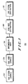
- FIG. 2, numeral 200 shows a block diagram of an embodiment of a system in accordance with the present invention.
- the present invention uses an end-to-end, closed-loop control mechanism to regulate the flow of cells entering the ATM network from a source end system for each connection.
- the network or each of one or more interconnected subnetworks through which the ATM connection flows, selectively uses a segment congestion control function.
- the segment congestion control mechanism monitors, for each connection, the EFCI state in cells leaving the egress edge of the subnetwork, and then communicates congestion state changes via backward TM cells to the ingress edge of the subnetwork. At the ingress edge, congestion state changes selectively regulate the flow of cells entering the subnetwork.
- the source end system (202) is utilized for transmitting cells to a serially coupled plurality of traffic management nodes (210, 212, 214, 216, 218, 220).
- the traffic management nodes (210, 212, 214, 216, 218, 220) are utilized for providing pathway(s) for cells across the network and for utilizing a segment traffic control mechanism for protecting nodes in a segment of the network against malfunctioning end systems.
- the first of the plurality of traffic management nodes is an ingress node (210), and also functions as a source edge node.
- the ingress node (210) is operably coupled to the source end system (202) and is used for providing at least cell entry-exit.
- the destination end system (208) is operably coupled to the egress node (220) and is used for receiving cells.
- the source end system (202) and destination end system (208) implement an end-to-end closed-loop rate control mechanism for controlling the flow of cells entering the network.
- Each subnetwork (204, 206, ...) includes: (1) an ingress node (210, 216, 7) that is operably coupled to receive cells from the source end system (202) or an egress node (214) of another subnetwork and is used for regulating the flow of cells into the subnetwork in accordance with a predetermined received TM cell scheme; (2) where selected, at least a first intermediate node (212, 218, ...) that is operably coupled to the ingress node (210, 216 7) and is used for providing a pathway for cells and for selectably sending TM cells to at least one of the ingress node and previous intermediate node(s) of the subnetwork, and (3) an egress node (214, 220, ...) that is operably coupled to the intermediate node(s) (212, 218, ...) for selectably providing TM cells to at least one of: the ingress node (210, 216, ...) of the subnetwork (204, 206, ...) and preselected intermediate node(s) (212,
- the end-to-end closed-loop rate control mechanism generally regulates the flow of cells leaving the source end system in accordance with Explicit Forward Congestion Indication (EFCI) cell information received at the destination end system, with state changes signaled back to the source end system using end-to-end (backward) TM cells.
- EFCI Explicit Forward Congestion Indication
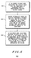
- transmitting the cells from the source edge node to the remaining traffic management nodes utilizing a segment traffic control mechanism for protecting nodes in a segment of the network against malfunctioning end systems (404), shown in FIG. 5, numeral 500 includes: (1) at an ingress pathway node, regulating the flow of cells into the subnetwork in accordance with a predetermined received TM cell scheme (502); (2) where the intermediate nodes are selected, providing a pathway for cells and for selectably sending TM cells from intermediate node(s) (504) to at least one of: the ingress pathway node and previous intermediate node(s) of the subnetwork; and (3) at an egress node, selectably providing TM cells (506) to at least one of: (3a) the ingress node of the subnetwork, and (3b) preselected intermediate node(s), together with providing a pathway for cells to one of: (3c) another subnetwork, and (3d) the destination end system.
- TM cell scheme 502
- the intermediate nodes are selected, providing a pathway for cells and
Landscapes
- Engineering & Computer Science (AREA)
- Computer Networks & Wireless Communication (AREA)
- Signal Processing (AREA)
- Data Exchanges In Wide-Area Networks (AREA)
Claims (10)
- Verkehrsverwaltungssystem ("TMS = traffic management system") zum Bereitstellen einer Zellflussregulation in einem Cell-Relay-Kommunikationsnetzwerk, umfassend:dadurch gekennzeichnet, dass die Mehrzahl von Verkehrsverwaltungsknoten einen Segmentverkehrssteuermechanismus (404) verwenden, um Knoten in einem Segment des Netzwerks gegen fehlerhaft funktionierende Endsysteme zu schützen, einschließlich des Quellenrandknotens; und(A) ein Quellenendsystem (102, 202), zum Übertragen von Zellen an einen Quellenrandknoten,(B) eine Mehrzahl von Verkehrsverwaltungsknoten (106, 206), die seriell an den Quellenrandknoten gekoppelt sind, zum Bereitstellen von einem oder mehreren Wegen für Zellen in dem Netzwerk, betriebsfähig an das Quellenendsystem gekoppelt, um zumindest einen Zell-Eintritt-Austritt zur Verfügung zu stellen, und einen Bestimmungsrandknoten, der seriell an die vorherige seriell gekoppelte Mehrzahl von einem oder mehreren Knoten gekoppelt ist, um zumindest einen Zell-Eintritt-Austritt zur Verfügung zu stellen, und(C) ein Bestimmungsendsystem (110, 208), das betriebsfähig an den Bestimmungsrandknoten gekoppelt ist, um Zellen zu empfangen;
dass das Quellenendsystem und das Bestimmungsendsystem einen Ende-zu-Ende-Raten-Steuermechanismus mit geschlossener Schleife implementieren, um den Fluss von Zellen zu steuern, die in das Netzwerk eintreten. - Verkehrsverwaltungssystem nach Anspruch 1, wobei die Mehrzahl von Verkehrsverwaltungsknoten umfasst:(A) mindestens ein erstes Unternetzwerk von Knoten (210, 212, 214, 216, 218, 220), die Verkehrsverwaltungszellen (TM-Zellen, "TM = traffic management") erzeugen, die an vorausgewählte vorherige Knoten innerhalb des Unternetzwerks gesendet werden, um den Segmentverkehrssteuermechanismus zu implementieren, und (B) das Bestimmungsendsystem, das TM-Zellen erzeugt, die an das Quellenendsystem gesendet werden, um den Ende-zu-Ende-Raten-Steuermechanismus mit geschlossener Schleife zu implementieren.
- Verkehrsverwaltungssystem nach Anspruch 2, wobei jedes Unternetzwerk umfasst:(A) einen Eingangsknoten (210, 216), der betriebsfähig so gekoppelt ist, dass er Zellen empfängt von entweder:(A1) dem Quellenendsystem, oder(A2) einem Ausgangsknoten eines weiteren Unternetzwerks, um den Fluss von Zellen in das Unternetzwerk gemäß einem vorbestimmten empfangenen TM-Zellschema zu regulieren,(B) wo ausgewählt, zumindest einen ersten Zwischenknoten (212, 218), der betriebsfähig an den Eingangsknoten gekoppelt ist, um einen Weg für Zellen zur Verfügung zu stellen und um die TM-Zellen wählbar an den Eingangsknoten und/oder einen oder mehrere vorausgehende Zwischenknoten des Unternetzwerks zu senden,(C) einen Ausgangsknoten (214, 220), der betriebsfähig an den oder die Zwischenknoten gekoppelt ist, um:(C1) wählbar TM-Zellen zur Verfügung zu stellen an:(C1a) den Eingangsknoten des Unternetzwerkes, und/oder(C1b) den oder die vorausgewählten Zwischenknoten, und(C2) einen Weg für Zellen zur Verfügung zu stellen an entweder:(C2a) ein weiteres Unternetzwerk oder(C2b) das Bestimmungsendsystem.
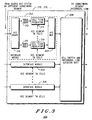
- Verkehrsverwaltungssystem, nach Anspruch 3, wobei der Segmentverkehrssteuermechanismus durch den Eingangsknoten implementiert ist, und wobei der Eingangsknoten umfasst:(A) eine Mehrzahl von Schnittstellenmodulen (302, 304, 306) mit jeweils VCC-Zellpuffern ("VCC = Virtual Channel Connection"/virtuelle Kanalverbindung) und jeweils VCC-segmentkontrollierter Zellflussregulation, zum Regulieren des Zellflusses durch das Unternetzwerk, wobei jedes betriebsfähig so gekoppelt ist, dass es Zellen empfangen kann von entweder:(A1) einem Quellenendsystem, oder(A2) einem von dem Unternetzwerk des Eingangsknotens verschiedenen Unternetzwerk, und(B) eine Zellschalt- und ZwischenknotenverbindungsWarteschlangeneinheit (308), die betriebsfähig an die Mehrzahl von Schnittstellenmodulen gekoppelt ist, um eine vorbestimmte Zwischenknotenverbindungs-Warteschlange der Zellen von den Schnittstellenmodulen zur Verfügung zu stellen, und, wo weiterhin ausgewählt:
wobei jedes Schnittstellenmodul umfasst C-F:(C) einen VCC-Demultiplexer (VCC DEMUX) (310), der betriebsfähig so gekoppelt ist, dass er Zellen empfangen und demultiplexen kann von entweder:(C1) einem Quellenendsystem, oder(C2) einem von dem Unternetzwerk des Eingangsknotens verschiedenen Unternetzwerk,(D) eine Mehrzahl von Puffern (312, 316), jeweils an den VCC DEMUX gekoppelt, um temporär eingehende Zellen zu halten, um ein Verschlimmern einer Überlastung entlang eines Verbindungsweges in dem Netzwerk zu vermeiden,(E) eine Mehrzahl von Zellflussregulatoren (314, 318), jeweils betriebsfähig an einen der Puffer und zum Empfangen von TM-Zellen von innerhalb des Unternetzwerkes gekoppelt, das eine virtuelle Kanalverbindung (VCC) verwendet, zum Regulieren des Zellflusses gemäß einem vorbestimmten Schema.(F) einen VCC-Multiplexer (VCC-MUX) (320), der betriebsfähig an die Mehrzahl von Zellflussregulatoren gekoppelt ist, um empfangen Zellen zu multiplexen. - Verkehrsverwaltungssystem nach Anspruch 2, wobei der Ende-zu-Ende-Raten-Steuermechanismus mit geschlossener Schleife den Fluss von Zellen reguliert, die das Quellenendsystem verlassen, gemäß einer Zelleninformation hinsichtlich einer expliziten Vorwärtsüberlastungsanzeige ("Explicit Forward Congestion Indication"), die an dem Bestimmungsendsystem empfangen wurde, wobei Überlastungszustandsveränderungen zurück an das Quellenendsystem unter Verwendung von Ende-zu-Ende-(Rückwärts)-TM-Zellen signalisiert werden.
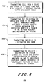
- Verkehrsverwaltungsverfahren zum Bereitstellen einer Zellflussregulation in einem Cell-Relay-Kommunikationsnetzwerk, das die Schritte umfasst:dadurch gekennzeichnet, dass:(A) Übertragen von Zellen von einem Quellenendsystem an einen Quellenrandknoten einer Mehrzahl von seriell gekoppelten Verkehrsverwaltungsknoten (402),(B) Übertragen der Zellen von den Quellenrandknoten an die verbleibenden Verkehrsverwaltungsknoten (404),(C) Übertragen der Zellen an einen Bestimmungsendrandknoten (406), und(D) Übertragen der Zellen an ein Bestimmungsendsystem (408) ;der Schritt des Übertragens der Zellen von dem Zellenrandknoten an die verbleibenden Verkehrsverwaltungsknoten das Verwenden eines Segementverkehrssteuermechanismus umfasst, der Knoten in einem Segment des Netzwerks gegen fehlerhaft funktionierende Endsysteme (404) schützt; unddas Quellenendsystem und das Bestimmungsendsystem einen Ende-zu-Ende-Raten-Steuermechanismus mit geschlossener Schleife implementieren, um den Fluss von Zellen, die in das Netzwerk (408) eintreten, zu steuern.
- Verkehrsverwaltungsverfahren nach Anspruch 6, das die Schritte umfasst:(A) das Erzeugen von Verkehrsverwaltungszellen (TM-Zellen, "TM = traffic management") durch die Mehrzahl von seriell gekoppelten Verkehrsverwaltungsknoten, wobei die TM-Zellen an vorausgewählte vorherige Knoten innerhalb des Unternetzwerks gesendet werden, zum Implementieren von Segmentverkehrssteuermechanismen, und(B) das Erzeugen von TM-Zellen durch das Bestimmungsendsystem, wobei die TM-Zellen an das Quellenendsystem gesendet werden, zum Implementieren des Ende-zu-Ende-Raten-Steuermechanismus mit geschlossener Schleife.
- Verkehrsverwaltungsverfahren nach Anspruch 7, das an der Mehrzahl von Verkehrsverwaltungsknoten die Schritte umfasst:(A) An einem Eingangswegeknoten, Regulieren des Flusses von Zellen in das Unternetzwerk gemäß einem vorbestimmten empfangenen TM-Zell-Schema (502),(B) Bereitstellen eines Weges für Zellen zum wählbaren Senden von TM-Zellen von einem oder mehreren Zwischenknoten: dem Eingangswegeknoten und/oder, wo gewählt, einem oder mehreren vorhergehenden Zwischenknoten des Unternetzwerks (504),(C) an einem Ausgangsknoten, wählbares Bereitstellen vom TM-Zellen an:(C2) Bereitstellen eines Weges für Zellen an entweder:(C1a) den Eingangsknoten des Unternetzwerks, und/oder(C1b) den oder die vorgewählten Zwischenknoten, und(C2a) ein weiteres Unternetzwerk oder(C2b) das Bestimmungsendsystem (506).
- Verkehrsverwaltungsverfahren nach Anspruch 8, wobei der Segmentverkehrssteuermechanismus durch den Eingangsknoten implementiert ist und die Schritte umfasst:(A) Verwenden einer Mehrzahl von Schnittstellenmodulen mit jeweils VCC-Zellpuffern ("VCC = Virtual Channel Connection"/virtuelle Kanalverbindung) und jeweils VCC-segmentkontrollierter Zellflussregulation, um den Zellfluss durch das Unternetzwerk zu regulieren, wobei jedes betriebsfähig so gekoppelt ist, dass es Zellen empfängt von entweder:(A1) einem Quellenendsystem, oder(A2) einem von dem Unternetzwerk des Eingangsknotens (602) verschiedenen Unternetzwerk, und(B) Verwenden einer Zellschalt- und Zwischenknotenverbindungs-Warteschlangeneinheit zum Bereitstellen einer vorbestimmten Zwischenknotenverbindungs-Warteschlange der Zellen von den Schnittstellenmodulen (604), und, wo weiterhin ausgewählt:
wobei das Verwenden einer Mehrzahl von Schnittstellenmodulen mit jeweils VCC-Zellpuffern und jeweils VCC-segmentkontrollierter Zellflussregulation, zum Regulieren des Zellflusses durch das Unternetzwerk, die Schritte umfasst C-F:(C) Verwenden eines VCC-Demultiplexers (VCC DEMUX), der betriebsfähig so gekoppelt ist, dass er Zellen empfangen und demultiplexen kann von entweder:(C1) einem Quellenendsystem, oder(C2) einem von dem Unternetzwerk des Eingangsknotens verschiedenen Unternetzwerk,(D) Verwenden einer Mehrzahl von Puffern zum temporären Halten von eingehenden Zellen, um ein Verschlimmern einer Überlastung entlang eines Verbindungsweges in dem Netzwerk zu vermeiden,(E) Verwenden einer Mehrzahl von Zellflussregulatoren, jeweils betriebsfähig an einen der Puffer und zum Empfangen von TM-Zellen von innerhalb des Unternetzwerkes gekoppelt, unter Verwendung einer virtuellen Kanalverbindung (VCC), zum Regulieren des Zellflusses gemäß einem vorbestimmten Schema,(F) Verwenden eines VCC-Multiplexers (VCC MUX) zum Multiplexen von empfangenen Zellen. - Verkehrverwaltungsverfahren nach Anspruch 8, wobei der Ende-zu-Ende-Raten-Steuermechanismus mit geschlossener Schleife den Schritt des Regulierens des Flusses von Zellen umfasst, die das Quellenendsystem verlassen, gemäß einer Zellinformation hinsichtlich einer expliziten Vorwärtsüberlastungsanzeige ("Explicit Forward Congestion Indication"), die an dem Bestimmungsendsystem empfangen wurde, wobei Statusänderungen an das Quellenendsystem unter Verwendung von Ende-zu-Ende-(Rückwärts)-TM-Zellen signalisiert werden.
Applications Claiming Priority (3)
| Application Number | Priority Date | Filing Date | Title |
|---|---|---|---|
| US18168194A | 1994-01-14 | 1994-01-14 | |
| US181681 | 1994-01-14 | ||
| PCT/US1994/013907 WO1995019675A1 (en) | 1994-01-14 | 1994-12-05 | Method and system for atm traffic management |
Publications (3)
| Publication Number | Publication Date |
|---|---|
| EP0689746A1 EP0689746A1 (de) | 1996-01-03 |
| EP0689746A4 EP0689746A4 (de) | 1999-11-24 |
| EP0689746B1 true EP0689746B1 (de) | 2005-10-19 |
Family
ID=22665312
Family Applications (1)
| Application Number | Title | Priority Date | Filing Date |
|---|---|---|---|
| EP95903674A Expired - Lifetime EP0689746B1 (de) | 1994-01-14 | 1994-12-05 | Verfahren und system zur verwaltung von atm-verkehr |
Country Status (5)
| Country | Link |
|---|---|
| EP (1) | EP0689746B1 (de) |
| AU (1) | AU670523B2 (de) |
| CA (1) | CA2154696C (de) |
| DE (1) | DE69434510T2 (de) |
| WO (1) | WO1995019675A1 (de) |
Families Citing this family (4)
| Publication number | Priority date | Publication date | Assignee | Title |
|---|---|---|---|---|
| GB9511314D0 (en) * | 1995-06-05 | 1995-08-02 | Gen Datacomm Adv Res | ATM network switch with congestion control |
| WO1997005724A1 (en) * | 1995-08-02 | 1997-02-13 | Nippon Telegraph And Telephone Corporation | Dynamic rate controller |
| JPH09266484A (ja) * | 1996-03-28 | 1997-10-07 | Mitsubishi Electric Corp | Atm交換機 |
| SE510170C2 (sv) * | 1997-05-16 | 1999-04-26 | Ericsson Telefon Ab L M | Metod och anordning för styrning av datapaketflöde medelst baktrycksmeddelande |
Family Cites Families (3)
| Publication number | Priority date | Publication date | Assignee | Title |
|---|---|---|---|---|
| US4190821A (en) * | 1978-10-02 | 1980-02-26 | Burroughs Corporation | Self-healing loop communications system |
| JPS608667B2 (ja) * | 1980-10-09 | 1985-03-05 | 株式会社明電舎 | ル−プ式デ−タハイウエイシステム |
| CA2096504C (en) * | 1993-05-18 | 1996-02-06 | Emanuel Weissmann | Self-healing drop and insert communication network |
-
1994
- 1994-12-05 EP EP95903674A patent/EP0689746B1/de not_active Expired - Lifetime
- 1994-12-05 CA CA002154696A patent/CA2154696C/en not_active Expired - Lifetime
- 1994-12-05 DE DE69434510T patent/DE69434510T2/de not_active Expired - Lifetime
- 1994-12-05 WO PCT/US1994/013907 patent/WO1995019675A1/en not_active Ceased
- 1994-12-05 AU AU12653/95A patent/AU670523B2/en not_active Expired
Also Published As
| Publication number | Publication date |
|---|---|
| EP0689746A4 (de) | 1999-11-24 |
| CA2154696C (en) | 2000-12-19 |
| DE69434510T2 (de) | 2006-07-27 |
| AU670523B2 (en) | 1996-07-18 |
| EP0689746A1 (de) | 1996-01-03 |
| CA2154696A1 (en) | 1995-07-20 |
| DE69434510D1 (de) | 2006-03-02 |
| WO1995019675A1 (en) | 1995-07-20 |
| AU1265395A (en) | 1995-08-01 |
Similar Documents
| Publication | Publication Date | Title |
|---|---|---|
| US5436891A (en) | Method and system for traffic management in cell relay networks | |
| US5765032A (en) | Per channel frame queuing and servicing in the egress direction of a communications network | |
| US7324511B2 (en) | Device, method and system for transferring frame | |
| EP0860070B1 (de) | Anordnung und verfahren in bezug auf paketflusssteuerung | |
| US6229788B1 (en) | Method and apparatus for traffic shaping in a broadband fiber-based access system | |
| US6301254B1 (en) | Virtual path ring protection method and apparatus | |
| US6879590B2 (en) | Methods, apparatuses and systems facilitating aggregation of physical links into logical link | |
| US5870384A (en) | Method and equipment for prioritizing traffic in an ATM network | |
| US7257121B2 (en) | System and method for mapping quality of service levels between MPLS and ATM connections in a network element | |
| JPH04100342A (ja) | トラヒック制御方式 | |
| JPH04156026A (ja) | 監視制御方法、監視制御装置及び交換システム | |
| JPH10271132A (ja) | パケット交換網におけるフロー制御方式 | |
| US5940368A (en) | Cell rate supervising system terminating congestion feedback loop | |
| EP1473895B1 (de) | Verfahren und Vorrichtung zur Multiplexübertragung | |
| EP0689746B1 (de) | Verfahren und system zur verwaltung von atm-verkehr | |
| US7136360B2 (en) | Available-bit-rate service in an asynchronous transfer mode based spacecraft network | |
| US8369320B2 (en) | Multiplexing apparatus and cell discard method | |
| EP0481447B1 (de) | Verfahren zur Steuerung eines Kommunikationsnetzes mit Knoten zur Vermittlung von virtuellen Kanälen und Knoten zur Vermittlung von virtuellen Wegen, sowie das genannte Kommunikationsnetz | |
| JPH10322344A (ja) | Atmトラヒツクのレート制御方式 | |
| AU2211600A (en) | Mechanism and method for dynamically allocating atm connections between exchanges | |
| KR100448711B1 (ko) | 광 링크 집속장치 및 그를 구비한 동기디지털계층전송시스템 | |
| KR100299138B1 (ko) | 에이티엠 장치에서 비실시간 트래픽 제어장치 및 방법 | |
| CA2326595A1 (en) | Method and apparatus for frame relay congestion interworking with abr flow-control loops | |
| Pazos | Bandwidth management and flow control for Internet backbones |
Legal Events
| Date | Code | Title | Description |
|---|---|---|---|
| PUAI | Public reference made under article 153(3) epc to a published international application that has entered the european phase |
Free format text: ORIGINAL CODE: 0009012 |
|
| AK | Designated contracting states |
Kind code of ref document: A1 Designated state(s): DE FR GB NL SE |
|
| 17P | Request for examination filed |
Effective date: 19960122 |
|
| RAP1 | Party data changed (applicant data changed or rights of an application transferred) |
Owner name: MOTOROLA, INC. |
|
| A4 | Supplementary search report drawn up and despatched |
Effective date: 19991008 |
|
| AK | Designated contracting states |
Kind code of ref document: A4 Designated state(s): DE FR GB NL SE |
|
| RIC1 | Information provided on ipc code assigned before grant |
Free format text: 6H 04L 12/56 A, 6H 04Q 11/04 B |
|
| 17Q | First examination report despatched |
Effective date: 20010608 |
|
| GRAP | Despatch of communication of intention to grant a patent |
Free format text: ORIGINAL CODE: EPIDOSNIGR1 |
|
| GRAS | Grant fee paid |
Free format text: ORIGINAL CODE: EPIDOSNIGR3 |
|
| GRAA | (expected) grant |
Free format text: ORIGINAL CODE: 0009210 |
|
| AK | Designated contracting states |
Kind code of ref document: B1 Designated state(s): DE FR GB NL SE |
|
| REG | Reference to a national code |
Ref country code: GB Ref legal event code: FG4D |
|
| REG | Reference to a national code |
Ref country code: SE Ref legal event code: TRGR |
|
| REF | Corresponds to: |
Ref document number: 69434510 Country of ref document: DE Date of ref document: 20060302 Kind code of ref document: P |
|
| ET | Fr: translation filed | ||
| PLBE | No opposition filed within time limit |
Free format text: ORIGINAL CODE: 0009261 |
|
| STAA | Information on the status of an ep patent application or granted ep patent |
Free format text: STATUS: NO OPPOSITION FILED WITHIN TIME LIMIT |
|
| 26N | No opposition filed |
Effective date: 20060720 |
|
| REG | Reference to a national code |
Ref country code: DE Ref legal event code: R081 Ref document number: 69434510 Country of ref document: DE Owner name: MOTOROLA MOBILITY, INC. ( N.D. GES. D. STAATES, US Free format text: FORMER OWNER: MOTOROLA, INC., SCHAUMBURG, ILL., US Effective date: 20110324 |
|
| REG | Reference to a national code |
Ref country code: FR Ref legal event code: TP Owner name: MOTOROLA MOBILITY, INC., US Effective date: 20110912 |
|
| REG | Reference to a national code |
Ref country code: NL Ref legal event code: TD Effective date: 20111229 Ref country code: NL Ref legal event code: SD Effective date: 20111229 |
|
| REG | Reference to a national code |
Ref country code: GB Ref legal event code: 732E Free format text: REGISTERED BETWEEN 20120112 AND 20120118 |
|
| PGFP | Annual fee paid to national office [announced via postgrant information from national office to epo] |
Ref country code: GB Payment date: 20131126 Year of fee payment: 20 Ref country code: SE Payment date: 20131206 Year of fee payment: 20 |
|
| PGFP | Annual fee paid to national office [announced via postgrant information from national office to epo] |
Ref country code: FR Payment date: 20131126 Year of fee payment: 20 Ref country code: NL Payment date: 20131206 Year of fee payment: 20 |
|
| PGFP | Annual fee paid to national office [announced via postgrant information from national office to epo] |
Ref country code: DE Payment date: 20131230 Year of fee payment: 20 |
|
| REG | Reference to a national code |
Ref country code: DE Ref legal event code: R071 Ref document number: 69434510 Country of ref document: DE |
|
| REG | Reference to a national code |
Ref country code: NL Ref legal event code: V4 Effective date: 20141205 |
|
| REG | Reference to a national code |
Ref country code: GB Ref legal event code: PE20 Expiry date: 20141204 |
|
| PG25 | Lapsed in a contracting state [announced via postgrant information from national office to epo] |
Ref country code: GB Free format text: LAPSE BECAUSE OF EXPIRATION OF PROTECTION Effective date: 20141204 |
|
| REG | Reference to a national code |
Ref country code: SE Ref legal event code: EUG |
|
| P01 | Opt-out of the competence of the unified patent court (upc) registered |
Effective date: 20230520 |