EP0690318A1 - A method for splicing optical fibers and a splicing apparatus capable of adjusting attenuation - Google Patents
A method for splicing optical fibers and a splicing apparatus capable of adjusting attenuation Download PDFInfo
- Publication number
- EP0690318A1 EP0690318A1 EP95102505A EP95102505A EP0690318A1 EP 0690318 A1 EP0690318 A1 EP 0690318A1 EP 95102505 A EP95102505 A EP 95102505A EP 95102505 A EP95102505 A EP 95102505A EP 0690318 A1 EP0690318 A1 EP 0690318A1
- Authority
- EP
- European Patent Office
- Prior art keywords
- attenuation
- optical fibers
- heating
- axes
- splicing
- Prior art date
- Legal status (The legal status is an assumption and is not a legal conclusion. Google has not performed a legal analysis and makes no representation as to the accuracy of the status listed.)
- Withdrawn
Links
Images


Classifications
-
- G—PHYSICS
- G02—OPTICS
- G02B—OPTICAL ELEMENTS, SYSTEMS OR APPARATUS
- G02B6/00—Light guides; Structural details of arrangements comprising light guides and other optical elements, e.g. couplings
- G02B6/24—Coupling light guides
- G02B6/26—Optical coupling means
- G02B6/264—Optical coupling means with optical elements between opposed fibre ends which perform a function other than beam splitting
- G02B6/266—Optical coupling means with optical elements between opposed fibre ends which perform a function other than beam splitting the optical element being an attenuator
-
- G—PHYSICS
- G02—OPTICS
- G02B—OPTICAL ELEMENTS, SYSTEMS OR APPARATUS
- G02B6/00—Light guides; Structural details of arrangements comprising light guides and other optical elements, e.g. couplings
- G02B6/24—Coupling light guides
- G02B6/255—Splicing of light guides, e.g. by fusion or bonding
- G02B6/2551—Splicing of light guides, e.g. by fusion or bonding using thermal methods, e.g. fusion welding by arc discharge, laser beam, plasma torch
Definitions
- This invention relates to a splicing method for optical fibers and a splicing apparatus capable of splicing two optical fibers with a desired attenuation (a designated attenuation), and capable of adjusting the attenuation.
- optical communication systems employing optical fibers have been developed and, in such a system, the necessity for splicing the optical fibers arises.
- an optical connector is used at portions at which connection and disconnection are necessary, and permanent connection by heating fusion, etc., is used at portions at which connection and disconnection are not necessary.
- Efforts have been made, in this permanent connection technology, that is, a splicing technology, to reduce the connection loss, and it has become possible to make connections with a loss of only about 0.05 dB.
- the splicing method according to the prior art brings the axes of two optical fibers into perfect conformity with each other and heats and fuses them by arc discharge, for example, so as to attain the low loss.
- Japanese Unexamined Patent Publication (Kokai) No. 4-243201 proposes a splicing construction wherein two optical fibers are spliced with their axes deviating from each other.
- This method of splicing the optical fibers with the axes thereof deviating from each other first determines a deviation of the axes corresponding to a designated attenuation on the basis of an approximation formula representing the relation between the deviation of the axes and the attenuation, then disposes the two optical fibers with the axes thereof deviating from each other so as to attain the deviation so determined, and heats and fuses the optical fibers by arc discharge so as to produce an optical attenuator.
- an apparatus for splicing optical fibers with a designated attenuation capable of adjusting the attenuation, which comprises heating means for heating and fusing opposed portions of two optical fibers, holding portions for holding the two optical fibers in opposition to each other in such a manner that the deviation of the axes of the two optical fibers can be adjusted, an attenuation measurement portion for measuring the attenuation between the two optical fibers, and control portion for controlling each of the heating means, the holding portions and the attenuation measurement portion, wherein the control portion includes a data base including data representing the relationship between an initial attenuation when the two optical fibers are so disposed as to oppose each other with the axes thereof deviating from each other and an attenuation which changes in accordance with the number of times of reheating, an axis adjustment portion for controlling the holding portions so that the initial attenuation described above can be obtained, and a heating control portion for controlling repetition of reheating by the heating means in
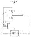
- Fig. 2 is a block diagram showing an apparatus according to an embodiment of the present invention.
- reference numerals 1 and 2 denote the optical fibers
- 10 is a splicing portion
- 20 is a control portion
- 11 and 12 are holding portions
- 13a and 13b are electrodes
- 14 is an auxiliary optical fiber
- 15 is a light source
- 16 is a power meter
- 21 is a control processing portion
- 22 is a data base
- 23 is an input operation portion
- 24 is an axis adjustment portion
- 25 is a heating control portion
- 26 is a monitor portion.
- the optical fibers 1 and 2 to be spliced are fitted to the holding portions 11 and 12.
- the holding portion 11 is so disposed as to be movable in the X, Y and Z directions, for example, and is controlled by the axis adjustment portion 24, whereas the holding portion 12 is kept stationary.
- Light is allowed to be incident from the light source 15 into the auxiliary optical fiber 14 and into the optical fiber 1, and light from the optical fiber 2 is compared, using the power meter 16, with light passing through the auxiliary optical fiber 14 as the reference.
- the X direction is a direction perpendicular to the sheet of the drawing, for example, the Y direction exists in the vertical direction of the drawing and the Z direction exists in the transverse direction of the drawing.
- the heating means can utilize laser heating, gas heating and so forth, but this embodiment represents the case where an arc discharge heating portion is disposed.
- the electrodes 13a and 13b are disposed in such a manner as to interpose the opposed portion of the optical fibers 1 and 2 and to orthogonally cross the opposed portion. The opposed portion of the optical fibers 1 and 2 is heated by the arc discharge when it is generated between the electrodes 13a and 13b.
- the monitor portion 26 has a construction such that it can accept the image of the opposed portion of the optical fibers 1 and 2 from the X and Y directions and can display it in magnification.
- the drawing shows an example of the image taken from either one of the X and Y directions. Since the size is displayed on the display screen, the deviation of the axes can be illustrated.
- FIG. 3 is a flowchart showing a splicing method according to an embodiment of the present invention.
- Splicing conditions inclusive of a designated attenuation are inputted by the input operation portion 23 (A1), and the optical fibers 1 and 2 are set to the splicing portion 10 (A2). In other words, the optical fibers 1 and 2 are held by the holding portions 11 and 12, respectively.
- the control processing portion 21 reads out the initial attenuation corresponding to the designated attenuation from the data base 22 (A3), and adjustment of the deviation of the axes is carried out by controlling the holding portion 11 by the axis adjustment portion 24 (A4). This deviation of the axes can be observed using the monitor portion 26.
- the light source 15 and the power meter 16 are operated so as to measure the attenuation (A5).
- the measured attenuation is compared with the initial attenuation (A6). When they are not equal, the flow returns to the step (A4), where the adjustment of the deviation of the axes is carried out by controlling the holding portion 11 by the axis adjustment portion 24.
- the voltage is applied from the heating control portion 25 to the electrodes 13a and 13b so as to generate an arc discharge, and the opposed portions of the optical fibers 1 and 2 are heated and fused by this arc discharge (A7).
- the attenuation of the optical fibers 1 and 2 so heated and fused is measured (A8), and the measured attenuation is compared with the designated attenuation (A9). When they are not equal, the arc discharge is again generated between the electrodes 13a and 13b and the heating fusion portion is reheated (A10). The attenuation is measured (A8), and reheating (A10) is repeated until the measured attenuation and the designated attenuation become equal to each other. When they become equal to each other, an appearance inspection is conducted (A11) and then the optical fibers 1, 2 are removed from the holding portions 11, 12 (A12). In this way, the splicing processing is completed.
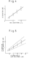
- the attenuation corresponding to the deviation of the axes of the optical fibers 1, 2 at the time of the axis adjustment drops after the optical fibers are connected by the arc discharge, and its relation is shown in Fig. 5, for example.
- the attenuation is set to 4 dB with the deviation of the axes being 8 ⁇ m and then heating fusion is effected by arc discharge, for example, the attenuation becomes 1 dB in the case of the characteristics represented by a curve of a solid line.
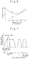
- Figure 6 is an explanatory view showing the relation between the number of times of discharge (number of times of reheating) and the change in the attenuation.
- the attenuation of 2 dB immediately after splicing becomes coincident with this designated attenuation by repeating arc discharge 10 times, and according to the experiments, the attenuation could be adjusted to the designated attenuation with accuracy of below 0.05 dB.
- the attenuation immediately after standard splicing which brings the axes of the optical fibers into conformity is 0.1 dB, the attenuation gradually increases by repeating arc discharge and conducting reheating as represented by the curve of the dotted line (b).
- the present invention splices the optical fibers 1, 2 with the axes thereof deviating from each other so that the attenuation becomes slightly greater than the designated attenuation, and then conducts fine adjustment of the attenuation by repeating an arc discharge so as to attain the designated attenuation.
- the conditions associated with the attenuation described above, etc. can be compiled into the data base and automation can be accomplished by using such a data base.
- Figure 7 is an explanatory view useful for explaining the splicing operation of the embodiment of the present invention, and shows the discharge power of the arc discharge (relative level) and a moving speed when the optical fiber 1 is moved towards the optical fiber 2.
- the holding portion 11 shown in Fig. 2 is moved at a predetermined speed towards the holding portion 12 under the control of the axis adjustment portion 24. In this way, the opposed portion of the optical fibers 1 and 2 is heated and fused by arc discharge. As described above, additional discharge is repeated until the attenuation becomes the designated attenuation.
- the preliminary heating time can be set to 150 ms, for example.
- the moving time can be set to 23 ms.
- preliminary heating time and moving time can be set so as to correspond to discharge power.
- additional discharge only the number of times of repetition can be controlled by setting the discharge time in advance, and discharge power, etc., can also be set in such a manner as to correspond to the difference between the measured attenuation and the designated attenuation whenever an additional discharge is started.
- the data base stores the data of the change of attenuation depending on discharge power and the number of times of discharge for the cases where the attenuation immediately after splicing is 2.0 dB, 2.5 dB, 3.0 dB, and so forth.
- the data base can be constituted of data which include the upper limit data of the number of times of additional discharge on the basis of the kind of the optical fibers to be spliced, discharge power, etc., limit data of an end face angle because there are many cases where the predetermined attenuation cannot be obtained when the end face angle of the optical fibers 1 and 2 exceeds a predetermined value, correspondence data of the difference range of the measured attenuation and the designated attenuation with respect to the discharge power of the additional discharge condition, and so forth.
- the control processing portion 21 inputs the kind of the optical fibers 1 and 2 and the designated attenuation from the input operation portion 23, looks up the data base 22, controls the axis adjustment portion 24 and the heating control portion 25, determines the initial attenuation corresponding to the designated attenuation, measures the attenuation by the light source 15 and the power meter 16, deviates the axes of the optical fibers 1 and 2, using the holding portion 11, so that the initial attenuation becomes equal to the measured attenuation, generates arc discharge between the electrodes 13a and 13b using the heating control portion 25, and heats and fuses the optical fibers 1, 2.
- the difference between the designated attenuation and the measured attenuation is obtained by measuring the attenuation between the optical fibers 1 and 2 so heated and fused, and determining which additional discharge conditions, etc., are selected. This additional discharge is repeated under the control of the heating control portion 25, and adjustment can be made so as to obtain the designated attenuation. In other words, complete automation can be accomplished, and the designated attenuation can be obtained with a high level of accuracy.
- control is also done in such a manner that after the optical fibers 1 and 2 are heated and fused with the axes thereof deviating from each other and reheating is repeated until the designated attenuation is obtained.
- Figure 9 is a flowchart useful for explaining another splicing method using the apparatus of the present invention.
- the splicing mode is the attenuation adjustment splice (a1) of the embodiment described above or a mode conversion splice (B1) for splicing optical fibers having mutually different core diameters, etc., or the standard splice (C1) for bringing the axes into conformity is determined depending on the splice condition input (A0).
- the control processing portion 21 determines the splicing condition by the input from the input operation portion 23 by using the splicing apparatus shown in Fig. 2.
- core adjustment is automatically made for the optical fibers 1, 2 held by the holding portions 11, 12, although their diameters are different (B2). This is carried out by moving the holding portion 11 in the X, Y and Z directions under the control of the axis adjustment portion 24, and adjusting the attenuation so that the attenuation measured by the light source 15 and the power meter 16 becomes minimal.
- arc discharge is generated between the electrodes 13a and 13b by the heating control portion 25 so as to heat and fuse the opposed portion of the optical fibers (B3).
- Measurement of the attenuation is then carried out (B4), and whether or not the measured attenuation is below the predetermined value is determined (B5).
- reheating is carried out (B6) and the measurement of the attenuation is conducted (B4).
- Whether or not the attenuation so measured is below the predetermined value is determined (B5).
Landscapes
- Physics & Mathematics (AREA)
- Engineering & Computer Science (AREA)
- Plasma & Fusion (AREA)
- General Physics & Mathematics (AREA)
- Optics & Photonics (AREA)
- Mechanical Coupling Of Light Guides (AREA)
- Light Guides In General And Applications Therefor (AREA)
- Control Of Non-Electrical Variables (AREA)
Applications Claiming Priority (2)
| Application Number | Priority Date | Filing Date | Title |
|---|---|---|---|
| JP6150709A JPH0815526A (ja) | 1994-07-01 | 1994-07-01 | 減衰量調整スプライス方法及びスプライス装置 |
| JP150709/94 | 1994-07-01 |
Publications (1)
| Publication Number | Publication Date |
|---|---|
| EP0690318A1 true EP0690318A1 (en) | 1996-01-03 |
Family
ID=15502700
Family Applications (1)
| Application Number | Title | Priority Date | Filing Date |
|---|---|---|---|
| EP95102505A Withdrawn EP0690318A1 (en) | 1994-07-01 | 1995-02-22 | A method for splicing optical fibers and a splicing apparatus capable of adjusting attenuation |
Country Status (2)
| Country | Link |
|---|---|
| EP (1) | EP0690318A1 (ja) |
| JP (1) | JPH0815526A (ja) |
Cited By (10)
| Publication number | Priority date | Publication date | Assignee | Title |
|---|---|---|---|---|
| US5897803A (en) * | 1995-04-28 | 1999-04-27 | Telefonaktiebolaget Lm Ericsson | Optical fiber attenuator made by fusion splicing offset fiber ends with extended heating after fusing |
| US6294760B1 (en) * | 1999-03-25 | 2001-09-25 | Fujikura Ltd. | Method for calibrating discharge heat energy of optical fiber splicing device |
| FR2815423A1 (fr) * | 2000-10-17 | 2002-04-19 | Opsitech Optical System Chip | Procede et dispositif de transmission d'une onde optique dans une structure de guidage optique |
| EP1202090A1 (en) * | 2000-09-21 | 2002-05-02 | Lucent Technologies Inc. | Dispersion-compensating fiber system having a bridge fiber and methods for making same |
| WO2002065176A1 (en) * | 2001-02-14 | 2002-08-22 | Telefonaktiebolaget Lm Ericsson (Publ) | Attenuator |
| US6464410B1 (en) * | 2000-06-14 | 2002-10-15 | Ciena Corporation | Attenuation splice, system and method therefor using estimation algorithm and closed loop intelligent control |
| US6478482B1 (en) * | 2000-06-14 | 2002-11-12 | Ciena Corporation | Attenuating splice, system, and method therefor |
| WO2003081309A3 (en) * | 2002-03-20 | 2004-02-05 | Intel Corp | In-line attenuation in optical fiber |
| CN109445029A (zh) * | 2018-12-13 | 2019-03-08 | 中电科仪器仪表(安徽)有限公司 | 一种大芯径光纤高能放电熔接装置和方法 |
| CN110542949A (zh) * | 2019-09-20 | 2019-12-06 | 光越科技(深圳)有限公司 | 一种用于硅光波导连接和耦合的光纤制作方法及加热装置 |
Citations (3)
| Publication number | Priority date | Publication date | Assignee | Title |
|---|---|---|---|---|
| EP0144136A1 (en) * | 1983-10-28 | 1985-06-12 | AT&T Corp. | Method for fabricating an optical attenuator by fusion splicing of optical fibres |
| US5285516A (en) * | 1992-03-18 | 1994-02-08 | Kaptron, Inc. | Fused fiber optic attenuator having axially overlapping fiber end portions |
| EP0594996A2 (de) * | 1992-10-30 | 1994-05-04 | Siemens Aktiengesellschaft | Optisches Dämpfungsglied, Verfahren zu seiner Herstellung und ein hierzu geeignetes thermisches Spleissgerät |
-
1994
- 1994-07-01 JP JP6150709A patent/JPH0815526A/ja not_active Withdrawn
-
1995
- 1995-02-22 EP EP95102505A patent/EP0690318A1/en not_active Withdrawn
Patent Citations (3)
| Publication number | Priority date | Publication date | Assignee | Title |
|---|---|---|---|---|
| EP0144136A1 (en) * | 1983-10-28 | 1985-06-12 | AT&T Corp. | Method for fabricating an optical attenuator by fusion splicing of optical fibres |
| US5285516A (en) * | 1992-03-18 | 1994-02-08 | Kaptron, Inc. | Fused fiber optic attenuator having axially overlapping fiber end portions |
| EP0594996A2 (de) * | 1992-10-30 | 1994-05-04 | Siemens Aktiengesellschaft | Optisches Dämpfungsglied, Verfahren zu seiner Herstellung und ein hierzu geeignetes thermisches Spleissgerät |
Non-Patent Citations (1)
| Title |
|---|
| PATENT ABSTRACTS OF JAPAN * |
Cited By (15)
| Publication number | Priority date | Publication date | Assignee | Title |
|---|---|---|---|---|
| US5897803A (en) * | 1995-04-28 | 1999-04-27 | Telefonaktiebolaget Lm Ericsson | Optical fiber attenuator made by fusion splicing offset fiber ends with extended heating after fusing |
| US6294760B1 (en) * | 1999-03-25 | 2001-09-25 | Fujikura Ltd. | Method for calibrating discharge heat energy of optical fiber splicing device |
| US6676307B1 (en) * | 2000-06-14 | 2004-01-13 | Ciena Corporation | Method and system for controlling splice attenuation |
| US6464410B1 (en) * | 2000-06-14 | 2002-10-15 | Ciena Corporation | Attenuation splice, system and method therefor using estimation algorithm and closed loop intelligent control |
| US6478482B1 (en) * | 2000-06-14 | 2002-11-12 | Ciena Corporation | Attenuating splice, system, and method therefor |
| EP1202090A1 (en) * | 2000-09-21 | 2002-05-02 | Lucent Technologies Inc. | Dispersion-compensating fiber system having a bridge fiber and methods for making same |
| WO2002033470A1 (fr) * | 2000-10-17 | 2002-04-25 | Opsitech Optical Sys On A Chip | Procede et dispositif de transmission d'une onde optique dans une structure de guidage optique |
| WO2002033470A3 (fr) * | 2000-10-17 | 2003-07-31 | Opsitech Optical Sys On A Chip | Procede et dispositif de transmission d'une onde optique dans une structure de guidage optique |
| FR2815423A1 (fr) * | 2000-10-17 | 2002-04-19 | Opsitech Optical System Chip | Procede et dispositif de transmission d'une onde optique dans une structure de guidage optique |
| WO2002065176A1 (en) * | 2001-02-14 | 2002-08-22 | Telefonaktiebolaget Lm Ericsson (Publ) | Attenuator |
| US7567745B2 (en) | 2001-02-14 | 2009-07-28 | Telefonaktiebolaget Lm Ericsson (Publ) | Optical attenuator and method of manufacture |
| WO2003081309A3 (en) * | 2002-03-20 | 2004-02-05 | Intel Corp | In-line attenuation in optical fiber |
| CN109445029A (zh) * | 2018-12-13 | 2019-03-08 | 中电科仪器仪表(安徽)有限公司 | 一种大芯径光纤高能放电熔接装置和方法 |
| CN110542949A (zh) * | 2019-09-20 | 2019-12-06 | 光越科技(深圳)有限公司 | 一种用于硅光波导连接和耦合的光纤制作方法及加热装置 |
| CN110542949B (zh) * | 2019-09-20 | 2020-11-06 | 光越科技(深圳)有限公司 | 一种用于硅光波导连接和耦合的光纤制作方法及加热装置 |
Also Published As
| Publication number | Publication date |
|---|---|
| JPH0815526A (ja) | 1996-01-19 |
Similar Documents
| Publication | Publication Date | Title |
|---|---|---|
| EP0697117B1 (en) | Controlled splicing of optical fibers | |
| EP0707226B1 (en) | Method of splicing polarization-maintaining optical fibers | |
| EP0690318A1 (en) | A method for splicing optical fibers and a splicing apparatus capable of adjusting attenuation | |
| CA1309773C (en) | Method for measuring splice loss of an optical fiber | |
| US20120073329A1 (en) | Large diameter optical waveguide splice | |
| US5772327A (en) | Automatic fusion-temperature control for optical fiber splicers | |
| US5897803A (en) | Optical fiber attenuator made by fusion splicing offset fiber ends with extended heating after fusing | |
| CA1196795A (en) | Apparatus and methods for testing lens structure | |
| US20030108307A1 (en) | Optical attenuator employing a fusion splice | |
| US6230522B1 (en) | Method for setting welding parameters for butt end joining optical fibers based on an offset | |
| JP3206607B2 (ja) | 光ファイバの融着接続装置 | |
| US20020094169A1 (en) | Method of laser welding | |
| JPS6046509A (ja) | 光フアイバのコア検出・軸合せ方法及びその装置 | |
| JPH0352604B2 (ja) | ||
| JPH0534646B2 (ja) | ||
| JP3359150B2 (ja) | 光部品の光損失測定方法 | |
| EP1174740A1 (en) | Method and apparatus for splicing optical fibers having different mode field diameters | |
| JPH0526167B2 (ja) | ||
| JP2783392B2 (ja) | 光ファイバの軸合わせ方法 | |
| US7228049B2 (en) | Optical fixed attenuator and process and apparatus for producing the same | |
| US7245814B1 (en) | Line attenuation device for monomode fibres and associated method for the production thereof | |
| CN111855145A (zh) | 一种光纤宏弯测试装置的使用方法 | |
| EP4488730A1 (en) | Multicore fiber connecting device and multicore fiber connecting method | |
| JPH0361926B2 (ja) | ||
| US20090238524A1 (en) | Apparatus for Thermal Connection of Optical Fibers, and Method for Thermal Connection of Optical Fibers |
Legal Events
| Date | Code | Title | Description |
|---|---|---|---|
| PUAI | Public reference made under article 153(3) epc to a published international application that has entered the european phase |
Free format text: ORIGINAL CODE: 0009012 |
|
| AK | Designated contracting states |
Kind code of ref document: A1 Designated state(s): DE FR GB |
|
| 17P | Request for examination filed |
Effective date: 19951218 |
|
| STAA | Information on the status of an ep patent application or granted ep patent |
Free format text: STATUS: THE APPLICATION HAS BEEN WITHDRAWN |
|
| 18W | Application withdrawn |
Withdrawal date: 19970616 |