EP0690526A2 - Coupleur en mode de courant avec mise à la masse améliorée - Google Patents
Coupleur en mode de courant avec mise à la masse améliorée Download PDFInfo
- Publication number
- EP0690526A2 EP0690526A2 EP95401469A EP95401469A EP0690526A2 EP 0690526 A2 EP0690526 A2 EP 0690526A2 EP 95401469 A EP95401469 A EP 95401469A EP 95401469 A EP95401469 A EP 95401469A EP 0690526 A2 EP0690526 A2 EP 0690526A2
- Authority
- EP
- European Patent Office
- Prior art keywords
- casing halves
- base
- coupler
- cover
- conductive member
- Prior art date
- Legal status (The legal status is an assumption and is not a legal conclusion. Google has not performed a legal analysis and makes no representation as to the accuracy of the status listed.)
- Withdrawn
Links
- 238000004804 winding Methods 0.000 claims description 8
- 230000008878 coupling Effects 0.000 description 4
- 238000010168 coupling process Methods 0.000 description 4
- 238000005859 coupling reaction Methods 0.000 description 4
- 239000002184 metal Substances 0.000 description 3
- 239000004020 conductor Substances 0.000 description 2
- 238000000034 method Methods 0.000 description 2
- 239000000725 suspension Substances 0.000 description 2
- 230000009471 action Effects 0.000 description 1
- 230000005540 biological transmission Effects 0.000 description 1
- 238000004140 cleaning Methods 0.000 description 1
- 230000006872 improvement Effects 0.000 description 1
- 230000001939 inductive effect Effects 0.000 description 1
- 239000000463 material Substances 0.000 description 1
- 230000013011 mating Effects 0.000 description 1
- 230000007246 mechanism Effects 0.000 description 1
- 238000012986 modification Methods 0.000 description 1
- 230000004048 modification Effects 0.000 description 1
- 238000004382 potting Methods 0.000 description 1
- 239000012858 resilient material Substances 0.000 description 1
- 229920001169 thermoplastic Polymers 0.000 description 1
- 239000004416 thermosoftening plastic Substances 0.000 description 1
Images
Classifications
-
- H—ELECTRICITY
- H01—ELECTRIC ELEMENTS
- H01R—ELECTRICALLY-CONDUCTIVE CONNECTIONS; STRUCTURAL ASSOCIATIONS OF A PLURALITY OF MUTUALLY-INSULATED ELECTRICAL CONNECTING ELEMENTS; COUPLING DEVICES; CURRENT COLLECTORS
- H01R31/00—Coupling parts supported only by co-operation with counterpart
- H01R31/005—Intermediate parts for distributing signals
-
- H—ELECTRICITY
- H01—ELECTRIC ELEMENTS
- H01R—ELECTRICALLY-CONDUCTIVE CONNECTIONS; STRUCTURAL ASSOCIATIONS OF A PLURALITY OF MUTUALLY-INSULATED ELECTRICAL CONNECTING ELEMENTS; COUPLING DEVICES; CURRENT COLLECTORS
- H01R13/00—Details of coupling devices of the kinds covered by groups H01R12/70 or H01R24/00 - H01R33/00
- H01R13/648—Protective earth or shield arrangements on coupling devices, e.g. anti-static shielding
- H01R13/658—High frequency shielding arrangements, e.g. against EMI [Electro-Magnetic Interference] or EMP [Electro-Magnetic Pulse]
- H01R13/6581—Shield structure
- H01R13/6582—Shield structure with resilient means for engaging mating connector
-
- H—ELECTRICITY
- H04—ELECTRIC COMMUNICATION TECHNIQUE
- H04L—TRANSMISSION OF DIGITAL INFORMATION, e.g. TELEGRAPHIC COMMUNICATION
- H04L25/00—Baseband systems
- H04L25/02—Details ; arrangements for supplying electrical power along data transmission lines
- H04L25/0264—Arrangements for coupling to transmission lines
- H04L25/0266—Arrangements for providing Galvanic isolation, e.g. by means of magnetic or capacitive coupling
Definitions
- This invention relates to the field of electrical connectors, and in particular to a current-mode coupler capable of non-invasively transferring electronic data signals to and from a twisted pair cable.
- Current-mode couplers are electrical connectors which enable sensing and transmission of low-level signal currents through an electrical conductor without an electrical connection to the conductor, thereby eliminating the need for direct wiring into the bus cable.
- the present invention is an improvement on the current-mode coupler disclosed in Patent No. 5,241,219, assigned to Amphenol Corporation, in which coupling to a twisted pair data bus cable is carried out by mating pairs of E-shaped electromagnets which surround the wires when the coupler is assembled to the data bus in order to establish an inductive coupling between the data bus and windings on the magnet cores, the windings being electrically connected to a control unit for sensing signals being transmitted along the data bus, and also for transmitting signals to the data bus.
- the coupler assembly of Patent No. 5,241,219 includes separate upper and lower metallic casing halves for housing the respective E-shaped magnetic cores.
- the cores are position relative to the data bus when the casing halves are latched together by means of a hook and slot arrangement at one end and a quarter turn latch at the other. Because of the unique design of the casing halves disclosed in Patent No. 5,241,219, the assembly procedure can be carried out in extremely narrow spaces, while nevertheless permitting an exceptionally stable coupling.
- the prior coupler design does have the disadvantage of less than optimal shielding resulting from the fact that the seam between the upper and lower casing, unless machined to a tolerance greater than is presently practical, incorporates relatively few points of electrical contact, and the points of contact are primarily butting rather than wiping points of contact, resulting in a relatively high impedance electrical connection between the conductive casing halves and an inadequate grounding of the casing half which is not otherwise secured to the structure on which the current-mode coupler is attached, for example a bulkhead in an aircraft.
- a current-mode coupler of the type intended to be used with a closed loop twisted pair data bus cable the wires of the cable being held in position relative to two pairs of E-cores forming a core structure for inductively transferring data signals to and from a printed circuit signal winding, wherein:
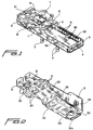
- Figure 1 is a perspective view of a preferred embodiment of a base portion for the current-mode coupler of the invention.
- Figure 2 is a perspective view of the cover of an upper shield housing for the current mode coupler of Figure 1.
- the current mode coupler constructed in accordance with the principles of a preferred embodiment of the invention includes a shield housing made up of a lower casing member or base 1 and an upper casing member or cover 2.
- Base 1 is essentially the same as the corresponding lower housing member of the coupler described in U.S. Patent No. 5,241,219, except that the quick-release mounting described in the patent has been replaced by screws in captivating standoffs 3 for facilitating mounting of the base to a bulkhead or panel (not shown), and the latching slot 4 is provided in a discrete member 5 at the end of base 1 rather than integrally with the base.
- the quick-release mounting described in the patent has been replaced by screws in captivating standoffs 3 for facilitating mounting of the base to a bulkhead or panel (not shown)
- the latching slot 4 is provided in a discrete member 5 at the end of base 1 rather than integrally with the base.
- the coupler of the presently preferred embodiment of the invention includes a holder 6 made up of a cover latching and alignment portion 10 and stamped and formed recessed portion 7 shaped to receive an elastomeric wire guide (not shown), the recess including openings 8 and 9 for accommodating core receiving projections on the elastomeric wire guide in order to position an E-shaped lower magnetic core (not shown) of the type described in U.S. Patent No. 5,241,219 relative to the base, the lower core being supported by a suspension (also not shown) to have one degree of freedom.
- Recessed portion 7 includes extensions 13 for receiving strain relief portions of the elastomeric guide and which extend into corresponding recesses (not shown) in base 1 in order to position holder 6, and consequently the resilient wire guide, relative to the base.
- cover 2 supports a plurality of E-shaped cores, shown in Figure 2 and designated by reference numerals 20 and 21.
- E-shaped cores 20 and 21 may optionally be resiliently supported, although such an additional resilient support will not ordinarily be necessary if the unique lower suspension described in U.S. Patent No. 5,241,219 is used.
- E-cores 20 and 21 are secured to a thermoplastic member (not shown) which insulates the magnetic cores from the housing and from a metal shielding plate 23 forming a completely shielded enclosure for the transformer electronics housed therein.
- a circuit board (not shown) provided in the enclosure formed by cover 2 and plate 23 carries a plurality of electrical components for transmitted signals to and from the core winding, including a read signal amplifier and a write signal driver circuit, both of which are completely shielded by the combination of metal plate 23 and cover 2.
- the windings are in the form of printed coils positioned on the circuit board to encircle openings in the circuit board through which the legs of the transformer cores extend.
- Read and write signals are preferably sent to and from the coupler via a conventional cylindrical connector (not shown) connected to the circuit board by wires (as opposed to the PCB tails described in U.S. Patent No. 5,241,219).
- the upper housing unit thus formed may be potted using conventional potting methods and materials.
- cover 2 opposite latch opening 11 is secured to the base 1 by a latching member 30 having a distal latching projection 30a designed to engage an upper edge of slot 4 to hold the upper housing member in place.
- latching member 30 is made of a resilient material, cover 2 can be snapped into base 1 in a single vertical motion, after the wires of a twisted pair or similar cable (not shown) have been untwisted and snapped into slots in the elastomeric wire guide described above.
- Projection 30a can also enter slot 4 via a horizontal motion parallel to the principal plane of the coupler.
- the improved grounding arrangement of the preferred embodiment of the invention includes a conductive member 38 secured to base 1 by any suitable means and which is made up of a plurality of fingers 31 having wiping surfaces 32 to form a low impedance ground path between the fingers and a ground channel formed by a corresponding substantially planar conductive member 33 secured to cover 2 via screws or other suitable fasteners, and which includes two arms 34 which extend downwardly in the direction of assembly of the cover to the base, the exterior surfaces 35 of the conductive member 33 thereby slidingly engaging wiping surfaces 32 of fingers 31 when the cover 2 is assembled to the base 1.
- fingers 31 are also provided in symmetrical fashion on side 36 of base 1 (the fingers on this side are obscured in Figure 1 by the side of the base), and are offset to allow angled entry of conductive member 33 without causing deformation of the fingers.
- grounding fingers 31 are preferably folded over base 1 to prevent hooking of the fingers by conductive member 33 cover.
- the inventors recognize that numerous variations of the preferred embodiment will undoubtedly occur to those skilled in the art, and intend that the invention be defined to include all such variations.
- the conductive member 33 may be provided on base 1, and fingers 31 may be provided in cover 2.
- the arrangement of the conductive member and resilient fingers which make up the improved grounding arrangement may be affected by changes in the manner in which the base and cover are assembled together.
- the cable with which the coupler is to be used need not be an unshielded, twisted pair cable or a closed loop data bus. Consequently, it is intended that the invention not be limited to the preferred embodiment described herein and illustrated in the drawings but rather that it be limited solely by the appended claims.
Landscapes
- Engineering & Computer Science (AREA)
- Power Engineering (AREA)
- Computer Networks & Wireless Communication (AREA)
- Signal Processing (AREA)
- Details Of Connecting Devices For Male And Female Coupling (AREA)
- Shielding Devices Or Components To Electric Or Magnetic Fields (AREA)
- Multi-Conductor Connections (AREA)
Applications Claiming Priority (2)
| Application Number | Priority Date | Filing Date | Title |
|---|---|---|---|
| US265772 | 1994-06-27 | ||
| US08/265,772 US5528088A (en) | 1994-06-27 | 1994-06-27 | Current mode coupler with improved grounding |
Publications (2)
| Publication Number | Publication Date |
|---|---|
| EP0690526A2 true EP0690526A2 (fr) | 1996-01-03 |
| EP0690526A3 EP0690526A3 (fr) | 1999-02-03 |
Family
ID=23011834
Family Applications (1)
| Application Number | Title | Priority Date | Filing Date |
|---|---|---|---|
| EP95401469A Withdrawn EP0690526A3 (fr) | 1994-06-27 | 1995-06-21 | Coupleur en mode de courant avec mise à la masse améliorée |
Country Status (2)
| Country | Link |
|---|---|
| US (1) | US5528088A (fr) |
| EP (1) | EP0690526A3 (fr) |
Cited By (1)
| Publication number | Priority date | Publication date | Assignee | Title |
|---|---|---|---|---|
| WO1998017036A1 (fr) * | 1996-10-11 | 1998-04-23 | W.L. Gore & Associates Gmbh | Equipement electrique de communication de donnees |
Families Citing this family (5)
| Publication number | Priority date | Publication date | Assignee | Title |
|---|---|---|---|---|
| US6794769B2 (en) * | 2001-05-01 | 2004-09-21 | Sanmina-Sci Corporation | Current mode coupler having a unitary casing |
| JP2007526209A (ja) * | 2003-04-14 | 2007-09-13 | エフ エム シー コーポレーション | 均一かつ熱可逆性低粘度ポリマンナンフィルムの伝達システム |
| TWD114121S1 (zh) * | 2005-05-18 | 2006-12-01 | 松下電工股份有限公司 | 光電變換用連接器 |
| TWD114125S1 (zh) * | 2005-05-18 | 2006-12-01 | 松下電工股份有限公司 | 光電變換用連接器 |
| TWD114123S1 (zh) * | 2005-05-18 | 2006-12-01 | 松下電工股份有限公司 | 光電變換用連接器 |
Citations (1)
| Publication number | Priority date | Publication date | Assignee | Title |
|---|---|---|---|---|
| US5241219A (en) | 1991-12-11 | 1993-08-31 | Amphenol Corporation | Current mode coupler |
Family Cites Families (6)
| Publication number | Priority date | Publication date | Assignee | Title |
|---|---|---|---|---|
| US4337989A (en) * | 1980-05-28 | 1982-07-06 | Amp Incorporated | Electromagnetic shielded connector |
| JPH03109825A (ja) * | 1989-09-25 | 1991-05-09 | Nippon Telegr & Teleph Corp <Ntt> | 無線装置 |
| US5128835A (en) * | 1990-08-31 | 1992-07-07 | Amp Incorporated | Data current coupler with internal shielding for electronic package |
| US5192832A (en) * | 1990-08-31 | 1993-03-09 | Amp Incorporated | Electromagnet insert for data current coupler |
| US5158481A (en) * | 1991-09-27 | 1992-10-27 | Amp Incorporated | Shielded electrical connector with torsioned shield interconnect |
| US5354951A (en) * | 1993-03-15 | 1994-10-11 | Leader Tech, Inc. | Circuit board component shielding enclosure and assembly |
-
1994
- 1994-06-27 US US08/265,772 patent/US5528088A/en not_active Expired - Fee Related
-
1995
- 1995-06-21 EP EP95401469A patent/EP0690526A3/fr not_active Withdrawn
Patent Citations (1)
| Publication number | Priority date | Publication date | Assignee | Title |
|---|---|---|---|---|
| US5241219A (en) | 1991-12-11 | 1993-08-31 | Amphenol Corporation | Current mode coupler |
Cited By (1)
| Publication number | Priority date | Publication date | Assignee | Title |
|---|---|---|---|---|
| WO1998017036A1 (fr) * | 1996-10-11 | 1998-04-23 | W.L. Gore & Associates Gmbh | Equipement electrique de communication de donnees |
Also Published As
| Publication number | Publication date |
|---|---|
| EP0690526A3 (fr) | 1999-02-03 |
| US5528088A (en) | 1996-06-18 |
Similar Documents
| Publication | Publication Date | Title |
|---|---|---|
| JP3446135B2 (ja) | モジュラージャックコネクタ | |
| JP4578522B2 (ja) | 低インダクタンスシールドコネクタ | |
| US20250329971A1 (en) | Couplers for single pair connectors | |
| US4838811A (en) | Modular connector with EMI countermeasure | |
| EP0502377B1 (fr) | Connecteur à filtre | |
| US6007368A (en) | Telecommunications connector with improved crosstalk reduction | |
| US20020042223A1 (en) | Stacked electrical connector for use with a filter insert | |
| EP1018789B1 (fr) | Connecteur de communication évolutif | |
| EP0986839B1 (fr) | Prise modulaire a element electronique incorpore | |
| EP0730324A2 (fr) | Connecteur de données slindé amélioré | |
| CA2144704A1 (fr) | Connecteur combine | |
| EP1089397B1 (fr) | Connecteur électrique ayant des moyens de retenue pour la fixation détachable d'un boîtier de composants | |
| WO1994013038A1 (fr) | Carte a circuits integres et faisceau de cables | |
| JPH04229573A (ja) | 接地構造を有するコネクタ | |
| US20110053418A1 (en) | Modular jack with two-piece housing and insert | |
| US5883787A (en) | Floating guided connector and method | |
| US4396242A (en) | Plug connector assembly | |
| EP1037314B1 (fr) | Ensemble de réceptacle et circuit imprimé servant à recevoir une fiche | |
| US5528088A (en) | Current mode coupler with improved grounding | |
| US5241219A (en) | Current mode coupler | |
| WO2019219847A1 (fr) | Connecteur à haute densité | |
| JP2948914B2 (ja) | 電気コネクタと印刷回路板 | |
| US6786742B2 (en) | Shield cable connector with latch lock system | |
| US6375496B1 (en) | Double stack electrical connector with integral ground plane | |
| JP2910311B2 (ja) | コネクタ |
Legal Events
| Date | Code | Title | Description |
|---|---|---|---|
| PUAI | Public reference made under article 153(3) epc to a published international application that has entered the european phase |
Free format text: ORIGINAL CODE: 0009012 |
|
| AK | Designated contracting states |
Kind code of ref document: A2 Designated state(s): DE ES FR GB IT |
|
| PUAL | Search report despatched |
Free format text: ORIGINAL CODE: 0009013 |
|
| AK | Designated contracting states |
Kind code of ref document: A3 Designated state(s): DE ES FR GB IT |
|
| 17P | Request for examination filed |
Effective date: 19990510 |
|
| 17Q | First examination report despatched |
Effective date: 19990803 |
|
| STAA | Information on the status of an ep patent application or granted ep patent |
Free format text: STATUS: THE APPLICATION IS DEEMED TO BE WITHDRAWN |
|
| 18D | Application deemed to be withdrawn |
Effective date: 19991214 |