EP0690608A2 - Filmabtastsystem und -verfahren - Google Patents
Filmabtastsystem und -verfahren Download PDFInfo
- Publication number
- EP0690608A2 EP0690608A2 EP95304183A EP95304183A EP0690608A2 EP 0690608 A2 EP0690608 A2 EP 0690608A2 EP 95304183 A EP95304183 A EP 95304183A EP 95304183 A EP95304183 A EP 95304183A EP 0690608 A2 EP0690608 A2 EP 0690608A2
- Authority
- EP
- European Patent Office
- Prior art keywords
- film
- location
- scanning
- scanner
- drum
- Prior art date
- Legal status (The legal status is an assumption and is not a legal conclusion. Google has not performed a legal analysis and makes no representation as to the accuracy of the status listed.)
- Withdrawn
Links
Images


Classifications
-
- H—ELECTRICITY
- H04—ELECTRIC COMMUNICATION TECHNIQUE
- H04N—PICTORIAL COMMUNICATION, e.g. TELEVISION
- H04N1/00—Scanning, transmission or reproduction of documents or the like, e.g. facsimile transmission; Details thereof
- H04N1/04—Scanning arrangements, i.e. arrangements for the displacement of active reading or reproducing elements relative to the original or reproducing medium, or vice versa
- H04N1/12—Scanning arrangements, i.e. arrangements for the displacement of active reading or reproducing elements relative to the original or reproducing medium, or vice versa using the sheet-feed movement or the medium-advance or the drum-rotation movement as the slow scanning component, e.g. arrangements for the main-scanning
- H04N1/121—Feeding arrangements
- H04N1/1215—Feeding using one or more cylindrical platens or rollers in the immediate vicinity of the main scanning line
-
- H—ELECTRICITY
- H04—ELECTRIC COMMUNICATION TECHNIQUE
- H04N—PICTORIAL COMMUNICATION, e.g. TELEVISION
- H04N1/00—Scanning, transmission or reproduction of documents or the like, e.g. facsimile transmission; Details thereof
- H04N1/04—Scanning arrangements, i.e. arrangements for the displacement of active reading or reproducing elements relative to the original or reproducing medium, or vice versa
- H04N1/19—Scanning arrangements, i.e. arrangements for the displacement of active reading or reproducing elements relative to the original or reproducing medium, or vice versa using multi-element arrays
- H04N1/191—Scanning arrangements, i.e. arrangements for the displacement of active reading or reproducing elements relative to the original or reproducing medium, or vice versa using multi-element arrays the array comprising a one-dimensional [1D] array
- H04N1/192—Simultaneously or substantially simultaneously scanning picture elements on one main scanning line
- H04N1/193—Simultaneously or substantially simultaneously scanning picture elements on one main scanning line using electrically scanned linear arrays, e.g. linear CCD arrays
-
- H—ELECTRICITY
- H04—ELECTRIC COMMUNICATION TECHNIQUE
- H04N—PICTORIAL COMMUNICATION, e.g. TELEVISION
- H04N2201/00—Indexing scheme relating to scanning, transmission or reproduction of documents or the like, and to details thereof
- H04N2201/04—Scanning arrangements
- H04N2201/0402—Arrangements not specific to a particular one of the scanning methods covered by groups H04N1/04 - H04N1/207
- H04N2201/0404—Scanning transparent media, e.g. photographic film
- H04N2201/0408—Scanning film strips or rolls
Definitions
- the invention relates to apparatus for generating images from optical film.
- the image being scanned was not covered, but was held by pressing adjacent film against a flat surface, thus only adjacent images were exposed to scratching and transfer of dust, and the image being scanned was not as precisely held flat.
- the present invention provides a method for scanning film comprising: disposing said film along a curved path , a segment of said path extending between and a first and a second location; directing light from said first location through said film and said segment to said second location; and collecting said light at said second location.
- This provides a film scanner adapted for scanning negative filmstrips which (with the advent of inexpensive computer processing) could capitalize on the vast potential provided by capturing negative images from filmstrips for subsequent postprocessing.
- Yet another object of the invention was to provide such a surface in a manner which would avoid damage to the film surface rising from contact therewith, such as surface scratches and the like.
- a further object of the invention was to provide for such a filmstrip scanner which could improve the accuracy of the scanning by means of rotary motion.
- the present invention provides a system for scanning film comprising: means for disposing said film along a curved path, a segment of said path extending between a first and a second location; means for directing light from said first directly location through said film and said segment to said second location; and means for collecting said light at said second location.
- the invention operates as follows:
- a scanner housing encloses a rotatable cylindrical drum, the outer surface having opposing rims or hubs which support respective outer edges of a film strip or slide to be scanned.
- the edges of the film are releasably held flat against respective rims by means of bands contacting respective radially outer edges of the film to maintain them against the respective outer rim surfaces of the drum whereby the film rotates with the drum's rotation past a scanner assembly.
- the scanner assembly is disposed internally of the housing adjacent one outer side of the drum and includes a linear array scanning transducer.
- a light source is located adjacent an opposing outer side of the drum at a location substantially diametrically opposed from the scanner assembly.
- a focusing lens assembly is disposed internally of the drum between the light source and the scanner assembly.
- the film being carried on the outer circumference of the rotating drum as the drum rotates, passes adjacent the light source. Light from the source thereby is directed from the light source through the film, the lens assembly, and impinges upon the scanning array whereupon the portion of the film adjacent the light source is thereby scanned.
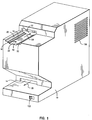
- FIG. 1 a pictorial view of a preferred embodiment of the film scanner of the invention is shown.
- a protective housing 10 is provided in which is disposed the various electrical, mechanical, and optical subsystems to be hereinafter described in greater detail.
- the scanner is provided with a film entry aperture 12 and film exit aperture 14.
- a strip of film or slide is introduced into the aperture 12 in a manner to be described in the direction of arrow 24.
- a transport mechanism internal to the housing 10 translates the film or slide through a semicircular path around a drum assembly enclosed within the housing 10.
- the film or slide is urged toward the back of the housing 10 and downwards, whereupon, after it is scanned, it exits the exit aperture 14 in the direction of arrow 26.
- a film/slide guide area 16 is preferably provided as part of the housing 10 and will be seen to include a plurality of pairs of guide shoulders 18, 20 and a guide surface 22, all of which lie in respective parallel planes.
- the purpose of such shoulders and surface is to accommodate film and transparencies of differing widths and to ensure that upon their introduction in the aperture 12, they are received by the transporting drum assembly in proper registry and orientation. In this manner they may be temporarily and reliably retained on the outer surface of the drum assembly during their traverse through the scanning path so as to maintain the integrity and resolution of the scan.
- a slide or film will be introduced into the film/slide guide area 16 so that it is parallel to the guide surface 22 and resting either upon the guide surface 22 or the opposing outer surfaces thereof are resting on the appropriate guide shoulders 18 or 20 (depending, of course, upon the width of the particular filmstrip or slide).
- the operator will then manually urge the film or slide along the direction of arrow 24, utilizing this guide surface or shoulders to maintain the orientation of the film/slide along the axis of arrow 24 until the film/slide is introduced sufficiently into the aperture 12 so as to contact the drum assembly (to be shown with reference to Fig. 2).
- the drum assembly Upon urging the film/slide sufficiently into the aperture 12, the drum assembly will grasp the filmstrip or slide, drawing it further within the aperture 12 until it is within the housing 10. Upon engagement of the film/slide by the drum assembly, the operator may thereafter release the film/slide, as the translation and scanning operation are thereafter automatic and internal to the housing 10. After completion of the scan the operator may retrieve the scanned film/slide which will be expelled out the aperture 14.
- Fig. 2 which is an illustration of the scanner similar to that of Fig. 1 with the housing 10 removed
- Fig. 5 and 8 how the film/slide is transported internally of the scanner and the optical path of the scan itself
- the internals of the scanner in a preferred embodiment, will include a drum assembly 28 (also shown pictorially in Fig. 7).
- the drum assembly will be seen to be comprised of a right and left disk-shaped half 30, 32.
- Each of these right and left halves of the drum assembly are identical and are supported by an axle 34 such that they may readily rotate together synchronously about the axle 34 as shown by arrow 56.
- a close view of the drum assembly 28 indicates that the right and left half thereof are provided with a respective right and left film support shoulder 38, 40.
- the filmstrip when the filmstrip is introduced in the upper film aperture 12, it will be travelling in the direction into the paper (at the top of Fig. 5 as illustrated therein).
- the filmstrip 36 As the filmstrip 36 is introduced further into the housing, it will eventually (due to the registry provided by the guide area 16 or guide shoulders 18, 20, (Fig. 1) be caused to be supported by the film support shoulders 38, 40, as shown in Fig. 5.
- a right and left film/slide retention band 52-54 are provided to gently and releasably hold the opposing inner edges of the filmstrip 36 against the outer surfaces of the film support shoulders 38 and 40. (This may better be seen better in Fig. 8.)
- a lens assembly 42 is shown (which may also be seen in Fig. 8) which includes a plurality of focusing lenses 74.
- a light source 114 (shown in Fig. 2) is disposed internally of the housing 10 at a light source location 64 shown in Fig. 8.
- transducer/scanner assembly 72 Disposed in a substantially diametrically opposed location from the light source is a transducer/scanner assembly 72 which includes a transducer 110 (preferably a linear array such as a TCD1300D available from Toshiba or a tricolour array such as the Toshiba TCD2301C - (when using a tricolour array, all three colours are scanned simultaneously and in registry and therefore only one colour needs to be measured for alignment, the other colours following)) and appropriate scanner control circuitry 112.
- a transducer 110 preferably a linear array such as a TCD1300D available from Toshiba or a tricolour array such as the Toshiba TCD2301C - (when using a tricolour array, all three colours are scanned simultaneously and in registry and therefore only one colour needs to be measured for alignment, the other colours following)
- a respective reticle On the inner surface of the right and left film support shoulders 38 and 40, a respective reticle will be imprinted. From the foregoing it will apparent that the scanner assembly will be looking in the direction into the page toward the lens assembly 42 and will thus be capable of scanning the reticles 130 as well as the inner surface of the film 36. Because the film is being transported along a drum assembly during the scan process and is stationary with respect to the drum assembly, the reticles 130 will provide a means for locating points in space and time along the longitudinal axis of the film 36 during the scanning process. Thus, these reticles 130 may serve as timing tracks or position locators during a scanning process. The scanning assembly would simply scan and recognize these gradient marks, translate and analyze them, and thereafter correlate them to the respective scan lines.
- a second example of use of such a feature is that after the scan process, if the mechanics have wobbled or the motor advance changed speed, any distortions to the image will also occur to these reticles. By correcting the image of these reticles in the software resizing, the image on the film follows into precise correction.
- the transducer/scan assembly 72 and light source at location 64 will preferably not be in perfect diametrically opposing relation but only substantially so because the axle 34 would otherwise lie in the optical path shown by arrow 70 interfering with the image to be scanned. This is not a problem because in almost all optical systems imaging film, the angle viewing the edges of the film is much steeper than the small angle required by offsetting the lens in this application.
- the transducer is normally a line array, also called a "linear" array, and therefor focus need be maintained across only a line on the film.
- the sensor surface can be tilted slightly while using the central axis of the lens in a focus technique common to view camera photography to maintain focus on a plane not perpendicular to the optical axis.
- TDI time delay integration
- transducer/scan assembly 72 consists of the transducer 110, which is preferably a linear sensor with sensor line positioned perpendicular to the rotation of the wheel, and associated scan control electronics 112, mounted on a focusing assembly 111.
- This assembly 111 may consist of a speaker that when energized moves the transducer 110 in a direction parallel to the optical axis to alter the focus and correct for scanning films of varying thickness.
- FIG. 6 a comparison to Fig. 5 will reveal that an alternate embodiment is shown for ensuring that the film 36 is releasably yet reliably retained on the right and left drum halves 30, 32, as it moves with the drum assembly during the scan process.
- right and left film retention ridges 44, 46 are provided on the respective drum assembly halves which extend circumferentially about their respective halves, serving the purpose essentially of the retention bands 52 and 54 of Fig. 5 and obviating their need.
- Fig. 7 yet an additional feature of the embodiment will be pointed out and described hereinafter in greater detail. It will be recalled that it is a feature of the embodiment to accommodate, in a single scanner, not only film in the form of strip but also in the form of filmstrips but slide transparencies as well. Accordingly, referring to Fig. 7, there will be seen depicted there in the right and left halves 30, 32 of the drum assembly 28, a corresponding right and left slide support slot 48, 50, each disposed in its respective drum assembly halve 30, 32.
- a slide is introduced into the entry aperture 12 of Fig. 1 (either as it rests on the guide shoulder pair 18, 20, or slides along the guide surface 22), as the drum assembly 28 rotates in the direction of arrow 56 (Fig. 7), eventually these slide slots 48, 50 will be in the vicinity of the entry aperture 12.
- the operator continuing to urge the slide into the aperture 12, eventually it will come to rest in and be supported by the slide slots 48, 50. This may be seen in Figs. 9, 12, and 14.
- the film/slide retention bands 52, 54 will serve the same purpose that they did with respect to the filmstrip 36, namely to firmly but releasably cause the slide 78 to be retained in the slide slots 48, 50 (Fig. 7) as the slide is rotationally transported in the semicircular path circumferentially on the outer periphery of the drum assembly about the axis 34 in the direction of arrow 56.
- each of the drum halves 30, 32 will be provided with tapered shoulders 80, 82, such that the slide 78, as it is introduced into the support slots 48, 50, will be guided into registry. In this manner the slide 78 will be retained in alignment gently by the walls of the tapered shoulders 80, 82, when the slide comes to rest on the bottom of slots 48, 50.
- slot pair 48, 50 While only one slot pair 48, 50, is shown in Fig. 7, this was done for simplicity of illustration. It will be readily apparent that with only one such slot pair, the operator would have to wait during introduction of a slide in the entry aperture 12 until this slot pair had rotated around into position to receive a next slide through aperture 12. Accordingly, additional such slot pairs 48, 50, for receiving slides may be disposed about the circumference of the drum assembly right and left halves 30, 32, so that a vacant such slot pair will be ready to receive a slide in a more timely fashion. Yet an additional benefit to providing for multiple such slides slot pairs 48, 50 is that a plurality of slides may thereby be introduced and engaged in the scanning process at a given time when disposed about the drum assembly 28 at numerous locations.
- Fig. 2 and Fig. 4 the drum assembly 28 may be seen, supported by the axle 34.
- the light source 114, lens assembly 42, and transducer/scan assembly 72 may be seen in Fig. 2.
- two upper retention band terminations 84, 85 are shown and a lower retention band termination block 88. These serve to tether or terminate opposite ends of each of the retention bands 52, 54. It may be desirable to provide for springs 76 terminating the bands 52, 54, which is disposed between the ends of the bands and the outer edges of the film or slide when riding on the band termination block 88.
- Such springs are to provide some "give" to the bands as material (e.g. film or slides) are disposed between the bands and the outer circumference of the drum assembly halves 30, 32, which they contact in order to accommodate the thickness of the film and/or slides.
- material e.g. film or slides
- the bands 52, 54 are terminated at both ends and the drum assembly 28 is in rotary motion contacting these bands, sliding friction will develop between the bands and the drum assembly 28. Accordingly, it has been found desirable to provide for such bands 52, 54, to be fashioned out of a teflon or like substance to facilitate this sliding motion.
- the springs 76 may be selected so as to provide the necessary amount of tension whereby the film and slides may be readily introduced and "sandwiched" between the drum assembly 28 surfaces and the bands 52, 54. Also, in passing, it will be noted that a power supply 106 is provided which will be described in greater detail with reference to Fig. 17.
- a means is required for effecting the rotational translation of the drum assembly 28 about the axle 34. Accordingly, a suitable electric motor 92 is provided and a drive belt 96, interconnecting the motor 92 and drum drive wheel 90 so as to provide this rotational movement in the direction of arrow 56 of the drum assembly 28.
- the orientation of the light source 114, lens assembly 42, and transducer/scanner assembly 72 along the optical axis 70 may also be seen more clearly in Fig. 3.
- Fig. 17 it will be appreciated that various electrical and electronic circuits and components must be provided to effect the scanning in accordance with the invention. Accordingly, in Fig. 17, a functional block diagram of such circuitry and components is depicted.
- the scan assembly 72, motor 92, light source 114, lens 42, and power supply 106 already previously discussed will be seen depicted therein.
- the scanner will be provided with a connection 100 to a suitable source of external power such as a 110 volt AC line.
- a power switch 102 also shown externally accessible in Fig. 1 will be provided in series with appropriate fusing 104 so as to energize the power supply.
- a power switch 102 also shown externally accessible in Fig. 1
- appropriate fusing 104 so as to energize the power supply.
- the general purpose power supply 106 depicted in Fig. 17 will generate the necessary supply of voltages as appropriate to power the light source, lens, motor, transducer, scan control, and the like, delivering power to such various components over power lines 108. It will be appreciated that the power developed by the supply 106 may take several forms as required by the various components, such as plus and minus DC voltages of various magnitudes, and the like.
- a computer/storage/controller I/O interface 118 is also shown in Fig. 17.
- the embodiment admits to several forms of scanner, depending upon the application, and thus may be substantially self contained and operated with an internal embedded controller or, in the alternative, may be intended to operate under control of an external computer or controller. In either case, means will be required for controlling operation of the various components just described and for at a minimum storing the scanning data derived from operation of the scanner (and even performing operations on such data if desired).
- a general purpose functional block 118 has been shown to first illustrate that the various components in the scanner may, if desired, be controlled either by a computer or controller as an integral part of the scanner or controlled by an external such computer or controller. It may, for example, be desirable to alter the rotation of the motor 92 to effect changes in resolution or the like. Similarly, it may be desirable to alter the spectrum of the light source or even the focus or other operation of the lens assembly if electronically controllable. Similarly, it may be desirable to electronically control the scanning operation, e.g. the operation of the scan control 112 and even the transducer 110 itself.
- address/data/control lines 122, 124 have been shown extending from the computer/storage/controller I/O interface 118 to these various components, illustrating that in accordance with conventional computer science practices, these various functional sub-assemblies may be controlled as desired with these data address and control lines.
- the purpose of the I/O interface 118 is to provide an interface between these various sub-assemblies and components of the scanner and a computer, controller, and/or storage depicted generally as block 120.
- scanned data may be simply generated at the transducer 110, delivered over lines 126 to the scan controller 112, whereupon the scanned data is delivered on line 124 through I/O interface 118 to appropriate storage which may even be contained within the scanner if desired.
- an imbedded controller may be provided as a part of the scanner and shown as block 120. It will provide appropriate address, data, and command functions through the I/O interface 118 to the various components so as to internally control their operation in accordance with software associated with the controller much in the manner that modern appliances such as microwave ovens are being controlled.
- the scanner may obviously be controlled and its data dumped to an external computer system also intended to be generally illustrated by block 120.
- an appropriate adapter such as a conventional parallel port connector may be provided in the scanner so as to facilitate this electrical connection of data address and control lines 122, 124, to an appropriate computer interface 118 and ultimately to the controlling computer 120.
- the computer will thus enable its operator or be enabled by appropriate software to control the various components depicted in the electrical/electronic circuitry of Fig. 7 of the scanner in any desired manner.
- the computer 120 may be provided with a program adjusting the manner in which the scan is made by the transducer, in which case, appropriate address, command, and data signals will be carried through the interface 118 over lines 124 to the scan control 112 and ultimately the transducer 110 to effect the desired form of scanning and data transmission back to the computer 120.
- an operator may enter into the computer 120 by means of a keyboard or the like, data indicating a particular type of film medium being introduced to the scanner or desired resolution.
- the computer 120 might, for example, generate appropriate address, data, and command signals on line 126 through the interface 118 on lines 122 to the motor 92 so as to adjust the motor speed.
- Fig. 15 an illustration of a scanned image 122 is depicted therein, wherein the scan was performed when the film had a curvature relative to the wheel during the scanning process, as for example when scanning a flat mounted slide which does not curve around the wheel.
- the actual rectilinear grid in the original medium was uniform.
- the grid became distorted as shown in the image 122 of Fig. 15.
- One of the features of the invention and improvements over the prior art was to address the problem depicted in Fig. 15. It will recalled from the background of the invention that a solution afforded in the prior art to avoid such distortion of Fig. 15 was to simply provide a linear magazine in which the film or slide could reside which had a transparent cover forcing the film flat against the magazine so as to avoid curvature. This however resulted in scratching of the film, leading to other distortions in the resulting scanned image.
- curvature of the film is thereby avoided, resulting in the desired accurate scanned image 124, such as that depicted in Fig. 16.
- the curvature in the resulting scanned image is avoided by transporting the film along an actuate path whereby at the point of scan the film is thereby in a flattened state.
- Such means for holding the film in the curved orientation are depicted, for example, in Figs. 5 and 6, employing bands 52, 54, for example, or the film retention ridges 44, 46.
- FIG. 18 a schematic illustration of various geometrical points in the scanning process is provided which will assist in providing more precise terminology describing aspects of the invention.
- First and second locations 168, and 170 are intended to schematically illustrate the location of the source of light and the scanning process along a scan line 164.
- the optical path of the scan is shown by line 166 intersecting the scan line 164, the film 36, and the first location of the light source 168. It will be noted that this line is offset by a small distance 172 from the axle 34 of the drum assembly so that the axle does not interfere with the scan process.
- a scanning area 150 is shown on the surface 172 of the film 36. It is a feature of the invention that this scan area being presented to the scanner will be maintained in a substantially flat configuration so as to avoid aberrations and distortions associated with scanning curved film as in the prior art. It will further be recalled that the area 150 is held rigid by reason of its disposition in an arcuate posture and the fact that it is held against the film support shoulders of the drum assembly by means of the bands, retention ridges, or the like, along the edges 152 and 154 of the film 36.
- the scanning process 170 occurs along a line that is moved across the film as the drum rotates. This makes the scanning area 150 on the film very thin, effectively a line. Even though the film 154 is curved in an arcuate manner, the film surface along the line defined by area 150 is held rigid and straight without the bowing normally associated with a flexible film held flat by the edges.
- optical path of the scan is "direct" in the sense that nothing impedes the passage of light from location 168 to location 170 other than the film itself. It will be recalled that in the prior art the film is sandwiched in a plastic holder or the like in order to flatten the film for the scan process, resulting in the light having to pass through this plastic in addition to the film, thereby adversely affecting the quality of the scan.
- the drum assembly 28 is in the form of a cylindrical drum. Accordingly, the arc 162 would essentially form a substantially semicircular arc 162 from the beginning point of the arc 156 to the end point 152, and, accordingly, would define a radius of curvature extending from the axle 34 to the inner surface 172 of the film 36.
- the invention is not intended to be so limited, and admits to other shapes of the arc 162.
- the first location 168 will be seen to be "outside" the arc 162 whereas the second location 170 may be said to be “within” the arc.
- a line 160 is further depicted transverse to and intersecting the arc 162. The line along which the linear scanning occurs, 164, will thus be seen preferentially to be parallel to this line 160 which traverses the film surface and intersects the arc.
Landscapes
- Engineering & Computer Science (AREA)
- Multimedia (AREA)
- Signal Processing (AREA)
- Facsimile Scanning Arrangements (AREA)
Applications Claiming Priority (2)
| Application Number | Priority Date | Filing Date | Title |
|---|---|---|---|
| US08/269,335 US5572339A (en) | 1994-06-30 | 1994-06-30 | Film scanning system and method |
| US269335 | 1994-06-30 |
Publications (2)
| Publication Number | Publication Date |
|---|---|
| EP0690608A2 true EP0690608A2 (de) | 1996-01-03 |
| EP0690608A3 EP0690608A3 (de) | 1996-05-15 |
Family
ID=23026819
Family Applications (1)
| Application Number | Title | Priority Date | Filing Date |
|---|---|---|---|
| EP95304183A Withdrawn EP0690608A3 (de) | 1994-06-30 | 1995-06-16 | Filmabtastsystem und -verfahren |
Country Status (3)
| Country | Link |
|---|---|
| US (1) | US5572339A (de) |
| EP (1) | EP0690608A3 (de) |
| JP (1) | JP3122332B2 (de) |
Cited By (3)
| Publication number | Priority date | Publication date | Assignee | Title |
|---|---|---|---|---|
| EP0882355A4 (de) * | 1996-02-21 | 2001-08-01 | Pakon Inc | Filmabtaster |
| US6421079B1 (en) | 1996-02-21 | 2002-07-16 | Eastman Kodak Company | Film scanner |
| JP2014230063A (ja) * | 2013-05-22 | 2014-12-08 | オノ・アンド・ジーアイテイー株式会社 | フィルムスキャン装置 |
Families Citing this family (7)
| Publication number | Priority date | Publication date | Assignee | Title |
|---|---|---|---|---|
| US6124885A (en) * | 1996-12-20 | 2000-09-26 | Eastman Kodak Company | Film gate and scanner, and method of scanning using the scanner |
| US6047121A (en) * | 1997-03-31 | 2000-04-04 | Compaq Computer Corp. | Method and apparatus for controlling a display monitor in a PC/TV convergence system |
| US6178016B1 (en) | 1998-05-22 | 2001-01-23 | Eastman Kodak Company | Imaging apparatus for a photographic film image scanner |
| US7468819B2 (en) * | 2003-06-04 | 2008-12-23 | Canon Kabushiki Kaisha | Image reading apparatus and transmitting original illuminating apparatus |
| DE102004018781B4 (de) * | 2004-04-15 | 2006-04-13 | Deutsches Zentrum für Luft- und Raumfahrt e.V. | Film-Scanner |
| DE102009017534A1 (de) * | 2009-04-17 | 2010-10-21 | Dft Digital Film Technology Holding Gmbh | Vorrichtung und Verfahren zum Durchleuchten eines Films |
| CN113951817A (zh) * | 2021-09-08 | 2022-01-21 | 苏州缔影数字医疗科技有限公司 | 一种口腔cr扫描系统 |
Citations (1)
| Publication number | Priority date | Publication date | Assignee | Title |
|---|---|---|---|---|
| US5266805A (en) | 1992-05-05 | 1993-11-30 | International Business Machines Corporation | System and method for image recovery |
Family Cites Families (5)
| Publication number | Priority date | Publication date | Assignee | Title |
|---|---|---|---|---|
| USRE23113E (en) * | 1944-02-25 | 1949-05-10 | Inside scanning facsimile | |
| US3640482A (en) * | 1970-03-19 | 1972-02-08 | Graphic Sciences Inc | Paper feed mechanism |
| US3958250A (en) * | 1975-02-27 | 1976-05-18 | Sequential Data Machines, Inc. | Graphic plotting systems |
| US4725891A (en) * | 1986-09-15 | 1988-02-16 | Matrix Instruments Inc. | Film image digitizer |
| US5088813A (en) * | 1990-07-27 | 1992-02-18 | Eastman Kodak Company | Film scanner |
-
1994
- 1994-06-30 US US08/269,335 patent/US5572339A/en not_active Expired - Fee Related
-
1995
- 1995-05-15 JP JP07116152A patent/JP3122332B2/ja not_active Expired - Fee Related
- 1995-06-16 EP EP95304183A patent/EP0690608A3/de not_active Withdrawn
Patent Citations (1)
| Publication number | Priority date | Publication date | Assignee | Title |
|---|---|---|---|---|
| US5266805A (en) | 1992-05-05 | 1993-11-30 | International Business Machines Corporation | System and method for image recovery |
Cited By (3)
| Publication number | Priority date | Publication date | Assignee | Title |
|---|---|---|---|---|
| EP0882355A4 (de) * | 1996-02-21 | 2001-08-01 | Pakon Inc | Filmabtaster |
| US6421079B1 (en) | 1996-02-21 | 2002-07-16 | Eastman Kodak Company | Film scanner |
| JP2014230063A (ja) * | 2013-05-22 | 2014-12-08 | オノ・アンド・ジーアイテイー株式会社 | フィルムスキャン装置 |
Also Published As
| Publication number | Publication date |
|---|---|
| JP3122332B2 (ja) | 2001-01-09 |
| EP0690608A3 (de) | 1996-05-15 |
| JPH0856307A (ja) | 1996-02-27 |
| US5572339A (en) | 1996-11-05 |
Similar Documents
| Publication | Publication Date | Title |
|---|---|---|
| JP3522918B2 (ja) | 画像入力装置 | |
| US5739897A (en) | Method and system for creating index prints on and/or with a photographic printer | |
| US5572339A (en) | Film scanning system and method | |
| JPH11164094A (ja) | 2重面式平台スキヤナーの2レンズ型収束装置 | |
| JPH0918669A (ja) | 原稿文書を走査するための装置 | |
| US4154524A (en) | Copying apparatus for thick and sheet originals | |
| JPH11168607A (ja) | 2重面式平台スキヤナー用の単一ランプ照明系 | |
| US5691805A (en) | Multiple format 3D photographic printer | |
| JP3545522B2 (ja) | 画像入力用レンズ装置およびその合焦位置の補正方法 | |
| JPH0918659A (ja) | 平台スキヤナー | |
| US3183771A (en) | Microfilm holder | |
| US6222612B1 (en) | Process and device for the output of electronic image signals, and a photographic copier | |
| US5973765A (en) | Method of and device for selectively printing one of an image formed on a photographic film and liquid crystal display panel | |
| US6115103A (en) | Scanning-exposure apparatus | |
| EP1187449A2 (de) | Passgenaue Filmstreifen | |
| US5301034A (en) | Production of properly oriented copies of transparent masters | |
| US5619306A (en) | Apparatus for duplicating X-ray type photographic films | |
| JPH08248518A (ja) | マイクロフィルムリーダとその検索方法 | |
| JPH09130557A (ja) | 画像入力装置 | |
| US6532058B2 (en) | Photographic scanner with focus control | |
| JP2613458B2 (ja) | スリット走査露光式複写カメラのピント位置割出露光装置 | |
| JPH09211558A (ja) | 結像装置および画像入力装置 | |
| JP3862232B2 (ja) | 画像入力装置 | |
| JPH0998341A (ja) | 画像入力装置 | |
| EP0692905A2 (de) | Bildabtastgerät |
Legal Events
| Date | Code | Title | Description |
|---|---|---|---|
| PUAI | Public reference made under article 153(3) epc to a published international application that has entered the european phase |
Free format text: ORIGINAL CODE: 0009012 |
|
| AK | Designated contracting states |
Kind code of ref document: A2 Designated state(s): DE FR GB |
|
| PUAL | Search report despatched |
Free format text: ORIGINAL CODE: 0009013 |
|
| AK | Designated contracting states |
Kind code of ref document: A3 Designated state(s): DE FR GB |
|
| STAA | Information on the status of an ep patent application or granted ep patent |
Free format text: STATUS: THE APPLICATION IS DEEMED TO BE WITHDRAWN |
|
| 18D | Application deemed to be withdrawn |
Effective date: 19961116 |