EP0690615A2 - Dispositif de reproduction d'images - Google Patents
Dispositif de reproduction d'images Download PDFInfo
- Publication number
- EP0690615A2 EP0690615A2 EP95201597A EP95201597A EP0690615A2 EP 0690615 A2 EP0690615 A2 EP 0690615A2 EP 95201597 A EP95201597 A EP 95201597A EP 95201597 A EP95201597 A EP 95201597A EP 0690615 A2 EP0690615 A2 EP 0690615A2
- Authority
- EP
- European Patent Office
- Prior art keywords
- video
- clock
- playback
- signal
- video signal
- Prior art date
- Legal status (The legal status is an assumption and is not a legal conclusion. Google has not performed a legal analysis and makes no representation as to the accuracy of the status listed.)
- Granted
Links
- 238000005070 sampling Methods 0.000 claims abstract description 22
- 239000013078 crystal Substances 0.000 abstract 2
- 230000005236 sound signal Effects 0.000 description 7
- 230000001360 synchronised effect Effects 0.000 description 7
- 230000006870 function Effects 0.000 description 6
- 230000006837 decompression Effects 0.000 description 3
- 230000006835 compression Effects 0.000 description 2
- 238000007906 compression Methods 0.000 description 2
- 230000001419 dependent effect Effects 0.000 description 2
- 238000000034 method Methods 0.000 description 2
- 239000010453 quartz Substances 0.000 description 2
- VYPSYNLAJGMNEJ-UHFFFAOYSA-N silicon dioxide Inorganic materials O=[Si]=O VYPSYNLAJGMNEJ-UHFFFAOYSA-N 0.000 description 2
- 238000005562 fading Methods 0.000 description 1
- 239000000203 mixture Substances 0.000 description 1
- 230000001960 triggered effect Effects 0.000 description 1
Images
Classifications
-
- H—ELECTRICITY
- H04—ELECTRIC COMMUNICATION TECHNIQUE
- H04N—PICTORIAL COMMUNICATION, e.g. TELEVISION
- H04N5/00—Details of television systems
- H04N5/04—Synchronising
-
- H—ELECTRICITY
- H04—ELECTRIC COMMUNICATION TECHNIQUE
- H04N—PICTORIAL COMMUNICATION, e.g. TELEVISION
- H04N5/00—Details of television systems
- H04N5/04—Synchronising
- H04N5/06—Generation of synchronising signals
- H04N5/067—Arrangements or circuits at the transmitter end
- H04N5/073—Arrangements or circuits at the transmitter end for mutually locking plural sources of synchronising signals, e.g. studios or relay stations
- H04N5/0736—Arrangements or circuits at the transmitter end for mutually locking plural sources of synchronising signals, e.g. studios or relay stations using digital storage buffer techniques
Definitions
- the invention relates to an arrangement for the playback of decompressed video and / or audio data in a video and an audio playback clock.
- Video and / or audio data that are in compressed form and that are decompressed for playback are displayed in a fixed playback clock.
- these clocks can optionally be independent of one another, in any case it can be clocks of different frequencies.
- This object is achieved in that means are provided for generating the video and / or the audio playback clock, which derive these playback clocks from an externally supplied digital video signal.
- the externally supplied digital video signal is therefore used to generate the playback clock of the video and / or audio signal which has arisen from compressed data.
- the video signal obtained from compressed data is reproduced in a reproduction clock which is in a fixed relation to that Clock of the externally supplied digital video signal is.
- these two video signals are synchronized with each other so that a combined display is possible.
- This can consist, for example, of a cross-fade between the signals, a mixture of the signals or the like. Even when simply switching between the two signals, there are no more disturbances.
- the playback clocks for playback of the compressed video and / or audio data can be derived from the sampling clock of the externally supplied video signal.
- Each digital video signal has a sampling clock which can be used directly as a playback clock, for example for the decompressed video data. This means that the two video signals are inevitably synchronized.
- the sampling clock of the externally supplied video signal can, as is provided according to a further embodiment of the invention, be derived from its horizontal synchronizing pulses. This has the advantage that even with fluctuations in the time base, such as those generated by video recorders, a perfect reproduction of both video signals is guaranteed.
- the compressed video and / or audio data, which are decompressed before playback can, for example, as is provided in accordance with a further embodiment, according to the Motion Pictures Expert Group (MPEG) recommendation.
- MPEG Motion Pictures Expert Group
- Compression and decompression methods are used for digital video - Data through more and more and also includes regulations for the compression of audio data.
- the means for generating the video and audio playback clock have at least one discrete time oscillator (DTO) which is clocked as a function of the sampling clock of the externally supplied video signal.
- DTO discrete time oscillator
- Such a discrete time oscillator has an input adder, to which on the one hand a constant input signal and on the other hand the output signal of a register is fed, the input of which is connected to the output of the adder. Because the overflow of the output signal of the adder stage is not taken into account, such an oscillator generates digital data at its output, which represent a sawtooth-shaped signal. A sinusoidal signal or a rectangular signal can be derived from this signal as desired.
- the working cycle of this DTO results from the cycle with which the register is clocked. For the arrangement according to the invention, it is advantageous to clock this register as a function of the sampling clock of the externally supplied video signal, since the output signal of the DTO is thus dependent on the sampling clock of the video signal.
- the output signal of the DTO can in turn be used to generate the video and / or audio playback clock of the decompressed data.
- the sampling frequencies can be different.
- the video sampling frequencies can also be selected differently if a DTO is also used to generate the video playback clock.
- the playback clock frequencies for the two signals can be chosen freely and even depending on Input signal can be switched. This means that different playback clock frequencies can be selected, which, however, are each dependent on the sampling clock of the externally supplied video signal.
- a further advantageous embodiment of the invention consists in that, as is provided in accordance with a further subclaim, the video playback clock is derived from the audio playback clock or the audio playback clock is derived from the video playback clock.
- the playback clocks for a video and an audio signal do not have to be obtained individually from the externally supplied digital video signal, but only one of the clocks can be obtained directly from the video signal, whereas the other clock is derived from the clock which in turn is from is derived from the externally supplied video signal.
- a system time clock (STC) with a frequency of 90 kHz is required for decompression of data encoded according to the MPEG recommendation.
- STC system time clock
- the arrangement according to the invention can advantageously be used, as is provided according to a further embodiment of the invention, in a computer, in particular a personal computer, which, in addition to decompressing the video and / or audio data, can also control the playback or even via does the computer screen itself.
- the computer is external to supply digital video signal from which the playback clock is generated, for example on a plug-in card that is connected to the computer bus.
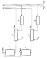
- the drawing shows a figure in which both compressed video and compressed audio data are decompressed, for example in accordance with the MPEG recommendation.
- the playback clocks are generated as a function of an externally supplied video signal, which is labeled V ext in the figure.
- This externally supplied video signal may also include an audio signal, which is identified in the figure with A ext .
- At least the signal V ext is a digital signal, that is to say has a sampling clock which can advantageously be used to generate the playback clocks of the decompressed video and / or audio signals.
- a frequency of 27 MHz is often chosen as the playback clock, which can advantageously be derived from the horizontal synchronous raster of the video signal.
- the figure shows a memory 1, which is an image memory in which a signal marked V MPEG in the figure is stored and decompressed.
- This signal compressed according to the MPEG recommendation, is decompressed in the image memory by means of external controls, not shown in the figure, and provided as a digital image signal.
- this signal is read into a first-in-first-out memory 2.
- decompressed video signal has not yet been synchronized to the clock of the externally supplied video signal V ext .
- the readout process from the first-in-first-out (FIFO) memory 2, depending on the output signal of a DTO (Discrete Time Oscillator), to which the sampling clock of the video signal V ext is fed on the input side.
- FIFO First-in-first-out
- a register is clocked with this sampling clock of the signal V ext in a manner not shown in the figure, the output signal of which is fed back to an input of an adder.
- a constant signal is supplied to the other input of the adder, not shown in the figure.
- the output signal of the adder reaches the clocked register, but the overflow of the output signal of the adder is not fed to this register.
- the register itself generates digital data which represent a sawtooth-shaped course as a result of the non-consideration of the overflow signal. If necessary, further stages can be connected downstream of the register, which generate a sinusoidal or a rectangular signal as a clock signal from this data, which represent a sawtooth-shaped course.
- the read clock from the FIFO 2 may be identical to the sampling clock of the external video signal V ext .
- DTO 3 can be omitted.
- a further memory 4 which receives audio data which can be assigned to the video signal V MPEG , for example, and which are to be reproduced together with the latter.
- V MPEG video signal
- These data point however, a much lower sampling clock, for example 44.1 kHz.
- a MPEG and are provided in the image memory 4 by means of external controls, which are not shown in the figure.
- This data is read into a FIFO memory 5 as a function of a fixed quartz clock T A.
- the data are read out from the FIFO memory 5 as a function of the output signal of a further DTO 6, to which the sampling clock of the external video signal V ext is fed on the input side.
- This DTO works in principle in the same way as the DTO 3, but produces an output clock of significantly lower frequency, which is designed for the audio data in accordance with the desired frequency of the playback clock.
- the data which is labeled A dec in the figure, is read out and is available for playback.
- Both the playback clock of the decompressed video data and the playback clock of the decompressed audio data are thus matched to the sampling clock of the externally supplied video signal V ext . Any fluctuations in this sampling clock, for example triggered by fluctuations in the time base of this signal, are taken into account in the playback clocks both of the data of the decompressed video signal and that of the audio signal. This enables a common representation of both signals, for example in the form of mixing the signals or cross-fading between the video signals. A synchronous reproduction of the decompressed audio data in relation to the decompressed video data is also ensured.
- the arrangement according to the figure can, for example, in one Computers can be provided on a plug-in card which is connected to the bus system of the computer.
- the external digital video signal is fed into the plug-in card.
- the further arrangement according to the figure is also provided on it.
- the data can be displayed on the computer monitor; however, the data can also be provided externally for playback on another image display device.
Landscapes
- Engineering & Computer Science (AREA)
- Multimedia (AREA)
- Signal Processing (AREA)
- Television Signal Processing For Recording (AREA)
- Compression Or Coding Systems Of Tv Signals (AREA)
- Television Systems (AREA)
- Signal Processing For Digital Recording And Reproducing (AREA)
Applications Claiming Priority (2)
| Application Number | Priority Date | Filing Date | Title |
|---|---|---|---|
| DE4422615A DE4422615A1 (de) | 1994-06-28 | 1994-06-28 | Bildwiedergabeanordnung |
| DE4422615 | 1994-06-28 |
Publications (3)
| Publication Number | Publication Date |
|---|---|
| EP0690615A2 true EP0690615A2 (fr) | 1996-01-03 |
| EP0690615A3 EP0690615A3 (fr) | 1996-12-11 |
| EP0690615B1 EP0690615B1 (fr) | 2000-03-22 |
Family
ID=6521725
Family Applications (1)
| Application Number | Title | Priority Date | Filing Date |
|---|---|---|---|
| EP95201597A Expired - Lifetime EP0690615B1 (fr) | 1994-06-28 | 1995-06-15 | Dispositif de reproduction d'images |
Country Status (5)
| Country | Link |
|---|---|
| US (1) | US5953068A (fr) |
| EP (1) | EP0690615B1 (fr) |
| JP (1) | JPH0832930A (fr) |
| KR (1) | KR100406622B1 (fr) |
| DE (2) | DE4422615A1 (fr) |
Families Citing this family (5)
| Publication number | Priority date | Publication date | Assignee | Title |
|---|---|---|---|---|
| US7369824B1 (en) | 1999-02-04 | 2008-05-06 | Chan Hark C | Receiver storage system for audio program |
| US6600908B1 (en) | 1999-02-04 | 2003-07-29 | Hark C. Chan | Method and system for broadcasting and receiving audio information and associated audio indexes |
| US7245707B1 (en) | 1999-03-26 | 2007-07-17 | Chan Hark C | Data network based telephone messaging system |
| JP3569205B2 (ja) * | 2000-06-09 | 2004-09-22 | シャープ株式会社 | 記録再生装置 |
| US20050281342A1 (en) * | 2004-06-22 | 2005-12-22 | Broadcom Corporation | Slow motion and high speed for digital video |
Family Cites Families (15)
| Publication number | Priority date | Publication date | Assignee | Title |
|---|---|---|---|---|
| GB2103457B (en) * | 1981-07-13 | 1985-01-09 | British Broadcasting Corp | Apparatus for processing a video signal and an associated sound signal |
| JPS59212891A (ja) * | 1983-05-18 | 1984-12-01 | パイオニア株式会社 | 同期回路 |
| US4580165A (en) * | 1984-04-12 | 1986-04-01 | General Electric Company | Graphic video overlay system providing stable computer graphics overlayed with video image |
| JPH0817008B2 (ja) * | 1985-05-24 | 1996-02-21 | 日本放送協会 | 映像信号時間軸補正装置 |
| US5065231A (en) * | 1988-09-26 | 1991-11-12 | Apple Computer, Inc. | Apparatus and method for merging input RGB and composite video signals to provide both RGB and composite merged video outputs |
| US5185603A (en) * | 1990-07-13 | 1993-02-09 | Medin David L | Apparatus for synchronizing computer and video images to be simultaneously displayed on a monitor and method for performing same |
| EP0523299A1 (fr) * | 1991-07-18 | 1993-01-20 | International Business Machines Corporation | Système et méthode pour combiner des signaux vidéo composite multiples |
| US5293540A (en) * | 1991-07-29 | 1994-03-08 | Nview Corporation | Method and apparatus for merging independently generated internal video with external video |
| CA2081140C (fr) * | 1992-01-14 | 1999-01-19 | Charles Thomas Rutherfoord | Methode et appareil de compression de signaux video |
| EP0572024A2 (fr) * | 1992-05-27 | 1993-12-01 | Kabushiki Kaisha Toshiba | Système de contrôle d'un affichage multimédia pour stocker des données d'image dans une mémoire de trame |
| US5287182A (en) * | 1992-07-02 | 1994-02-15 | At&T Bell Laboratories | Timing recovery for variable bit-rate video on asynchronous transfer mode (ATM) networks |
| JP3496725B2 (ja) * | 1992-10-16 | 2004-02-16 | ソニー株式会社 | 多重化データ分離装置 |
| JPH06178149A (ja) * | 1992-12-09 | 1994-06-24 | Matsushita Electric Ind Co Ltd | 映像復号化装置 |
| US5406306A (en) * | 1993-02-05 | 1995-04-11 | Brooktree Corporation | System for, and method of displaying information from a graphics memory and a video memory on a display monitor |
| US5541666A (en) * | 1994-07-06 | 1996-07-30 | General Instrument | Method and apparatus for overlaying digitally generated graphics over an analog video signal |
-
1994
- 1994-06-28 DE DE4422615A patent/DE4422615A1/de not_active Withdrawn
-
1995
- 1995-06-15 US US08/491,009 patent/US5953068A/en not_active Expired - Fee Related
- 1995-06-15 EP EP95201597A patent/EP0690615B1/fr not_active Expired - Lifetime
- 1995-06-15 DE DE59508028T patent/DE59508028D1/de not_active Expired - Lifetime
- 1995-06-23 KR KR1019950017008A patent/KR100406622B1/ko not_active Expired - Fee Related
- 1995-06-26 JP JP7159194A patent/JPH0832930A/ja active Pending
Non-Patent Citations (1)
| Title |
|---|
| None |
Also Published As
| Publication number | Publication date |
|---|---|
| EP0690615B1 (fr) | 2000-03-22 |
| KR100406622B1 (ko) | 2004-03-02 |
| KR960003294A (ko) | 1996-01-26 |
| JPH0832930A (ja) | 1996-02-02 |
| DE59508028D1 (de) | 2000-04-27 |
| EP0690615A3 (fr) | 1996-12-11 |
| US5953068A (en) | 1999-09-14 |
| DE4422615A1 (de) | 1996-01-04 |
Similar Documents
| Publication | Publication Date | Title |
|---|---|---|
| DE69419609T2 (de) | Synchronisieren von digitalen audiosignalen mit digitalen videosignalen | |
| DE69525908T2 (de) | Ton-/Videosynchronisator | |
| DE69218476T2 (de) | Frequenzgenerator für eine Synchronverriegelung | |
| DE69632664T2 (de) | Dekodierung von Informationsseiten, die Titelinformation und Seitendaten umfassen | |
| DE69523321T2 (de) | Vorrichtung zur dekodierung von digitalen videosignalen | |
| DE69619608T2 (de) | Fernsehsignalaufnahme- und -wiedergabeanlage | |
| DE69735034T2 (de) | Vorrichtung zum Verarbeiten eines Videosignals | |
| DE69522697T2 (de) | Verfahren und vorrichtung zur programmierbaren ton-/videosynchronisierung für multimediasysteme | |
| DE2420830C2 (de) | Verfahren und Anordnung zur Bandbreitenkompression eines Videosignals | |
| AT389608B (de) | Digitaler geschwindigkeitsfehlerkompensator | |
| DE69907136T2 (de) | Videosignal-bearbeitungsverfahren und -anlage | |
| DE69734548T2 (de) | Verfahren und Vorrichtung zur magnetischen Wiedergabe | |
| EP0690615B1 (fr) | Dispositif de reproduction d'images | |
| DE4127281C2 (de) | Schaltung zur Rekonstruktion eines Synchronsignalgemischs für eine Videoaufzeichnungs- und -wiedergabeeinrichtung | |
| DE3685850T2 (de) | Videosignalsteuerschaltung. | |
| EP0421017B1 (fr) | Dispositif d'insertion d'image dans l'image pour un récepteur de télévision avec un seul tuner | |
| DE19545356A1 (de) | Verfahren und Vorrichtung zur Überlagerung von Stereo-Videobildern | |
| DE10001369A1 (de) | Verfahren und Schaltungsanordnung zur Grafikdarstellung, insbesondere in einem digitalen Fernsehgerät | |
| DE69428701T2 (de) | Medien pipeline mit mehrwegevideoverarbeitung und wiedergabe | |
| DE19930824C2 (de) | Bild- und Tonwiedergabegerät und Verfahren für dessen Betrieb | |
| DE69524343T2 (de) | Schaltung zum Verarbeiten eines Audiosignals und Video-/Audiodekoder | |
| DE69409012T2 (de) | Vorrichtung zum Verarbeiten eines Teletextsignals | |
| DE19744712A1 (de) | Vorrichtung zur gleichzeitigen Darstellung von TV- und PC-Bildern | |
| DE69938490T2 (de) | Kodierer mit sanften Tonübergängen | |
| DE68919052T2 (de) | Magnetband-Aufnahme-/Wiedergabegerät. |
Legal Events
| Date | Code | Title | Description |
|---|---|---|---|
| PUAI | Public reference made under article 153(3) epc to a published international application that has entered the european phase |
Free format text: ORIGINAL CODE: 0009012 |
|
| AK | Designated contracting states |
Kind code of ref document: A2 Designated state(s): DE FR GB |
|
| PUAL | Search report despatched |
Free format text: ORIGINAL CODE: 0009013 |
|
| AK | Designated contracting states |
Kind code of ref document: A3 Designated state(s): DE FR GB |
|
| 17P | Request for examination filed |
Effective date: 19970611 |
|
| RAP3 | Party data changed (applicant data changed or rights of an application transferred) |
Owner name: KONINKLIJKE PHILIPS ELECTRONICS N.V. Owner name: PHILIPS PATENTVERWALTUNG GMBH |
|
| GRAG | Despatch of communication of intention to grant |
Free format text: ORIGINAL CODE: EPIDOS AGRA |
|
| 17Q | First examination report despatched |
Effective date: 19990610 |
|
| GRAG | Despatch of communication of intention to grant |
Free format text: ORIGINAL CODE: EPIDOS AGRA |
|
| GRAH | Despatch of communication of intention to grant a patent |
Free format text: ORIGINAL CODE: EPIDOS IGRA |
|
| RAP3 | Party data changed (applicant data changed or rights of an application transferred) |
Owner name: KONINKLIJKE PHILIPS ELECTRONICS N.V. Owner name: PHILIPS CORPORATE INTELLECTUAL PROPERTY GMBH |
|
| GRAH | Despatch of communication of intention to grant a patent |
Free format text: ORIGINAL CODE: EPIDOS IGRA |
|
| GRAA | (expected) grant |
Free format text: ORIGINAL CODE: 0009210 |
|
| AK | Designated contracting states |
Kind code of ref document: B1 Designated state(s): DE FR GB |
|
| REF | Corresponds to: |
Ref document number: 59508028 Country of ref document: DE Date of ref document: 20000427 |
|
| ET | Fr: translation filed | ||
| GBT | Gb: translation of ep patent filed (gb section 77(6)(a)/1977) |
Effective date: 20000613 |
|
| PLBE | No opposition filed within time limit |
Free format text: ORIGINAL CODE: 0009261 |
|
| STAA | Information on the status of an ep patent application or granted ep patent |
Free format text: STATUS: NO OPPOSITION FILED WITHIN TIME LIMIT |
|
| 26N | No opposition filed | ||
| REG | Reference to a national code |
Ref country code: GB Ref legal event code: IF02 |
|
| REG | Reference to a national code |
Ref country code: GB Ref legal event code: 732E |
|
| REG | Reference to a national code |
Ref country code: GB Ref legal event code: 732E |
|
| REG | Reference to a national code |
Ref country code: FR Ref legal event code: TP |
|
| REG | Reference to a national code |
Ref country code: FR Ref legal event code: GC |
|
| REG | Reference to a national code |
Ref country code: FR Ref legal event code: GC |
|
| PGFP | Annual fee paid to national office [announced via postgrant information from national office to epo] |
Ref country code: FR Payment date: 20100709 Year of fee payment: 16 |
|
| PGFP | Annual fee paid to national office [announced via postgrant information from national office to epo] |
Ref country code: GB Payment date: 20100609 Year of fee payment: 16 |
|
| REG | Reference to a national code |
Ref country code: FR Ref legal event code: GC |
|
| REG | Reference to a national code |
Ref country code: DE Ref legal event code: R409 Ref document number: 59508028 Country of ref document: DE Ref country code: DE Ref legal event code: R119 Ref document number: 59508028 Country of ref document: DE |
|
| REG | Reference to a national code |
Ref country code: DE Ref legal event code: R409 Ref document number: 59508028 Country of ref document: DE |
|
| GBPC | Gb: european patent ceased through non-payment of renewal fee |
Effective date: 20110615 |
|
| REG | Reference to a national code |
Ref country code: DE Ref legal event code: R084 Ref document number: 59508028 Country of ref document: DE Effective date: 20110426 Ref country code: DE Ref legal event code: R084 Ref document number: 59508028 Country of ref document: DE Effective date: 20111202 |
|
| REG | Reference to a national code |
Ref country code: FR Ref legal event code: AU Effective date: 20120126 |
|
| REG | Reference to a national code |
Ref country code: FR Ref legal event code: ST Effective date: 20120229 |
|
| PG25 | Lapsed in a contracting state [announced via postgrant information from national office to epo] |
Ref country code: FR Free format text: LAPSE BECAUSE OF NON-PAYMENT OF DUE FEES Effective date: 20110630 |
|
| REG | Reference to a national code |
Ref country code: FR Ref legal event code: TP Owner name: TRIDENT MICROSYSTEMS (FAR EAST) LTD., KY Effective date: 20120418 |
|
| PG25 | Lapsed in a contracting state [announced via postgrant information from national office to epo] |
Ref country code: GB Free format text: LAPSE BECAUSE OF NON-PAYMENT OF DUE FEES Effective date: 20110615 |
|
| REG | Reference to a national code |
Ref country code: DE Ref legal event code: R082 Ref document number: 59508028 Country of ref document: DE Representative=s name: EPPING HERMANN FISCHER, PATENTANWALTSGESELLSCH, DE |
|
| REG | Reference to a national code |
Ref country code: DE Ref legal event code: R082 Ref document number: 59508028 Country of ref document: DE Representative=s name: EPPING HERMANN FISCHER PATENTANWALTSGESELLSCHA, DE Effective date: 20121023 Ref country code: DE Ref legal event code: R082 Ref document number: 59508028 Country of ref document: DE Representative=s name: EPPING HERMANN FISCHER, PATENTANWALTSGESELLSCH, DE Effective date: 20121023 Ref country code: DE Ref legal event code: R081 Ref document number: 59508028 Country of ref document: DE Owner name: ENTROPIC COMMUNICATIONS, INC., SAN DIEGO, US Free format text: FORMER OWNER: TRIDENT MICROSYSTEMS (FAR EAST) LTD., GRAND CAYMAN, KY Effective date: 20121023 Ref country code: DE Ref legal event code: R081 Ref document number: 59508028 Country of ref document: DE Owner name: ENTROPIC COMMUNICATIONS, INC., US Free format text: FORMER OWNER: TRIDENT MICROSYSTEMS (FAR EAST) LTD., GRAND CAYMAN, KY Effective date: 20121023 |
|
| PGFP | Annual fee paid to national office [announced via postgrant information from national office to epo] |
Ref country code: DE Payment date: 20130627 Year of fee payment: 19 |
|
| REG | Reference to a national code |
Ref country code: DE Ref legal event code: R119 Ref document number: 59508028 Country of ref document: DE |
|
| PG25 | Lapsed in a contracting state [announced via postgrant information from national office to epo] |
Ref country code: DE Free format text: LAPSE BECAUSE OF NON-PAYMENT OF DUE FEES Effective date: 20150101 |