EP0690651A2 - Netz mit optischer Raumkoppelanordnung und einem Endgerät - Google Patents
Netz mit optischer Raumkoppelanordnung und einem Endgerät Download PDFInfo
- Publication number
- EP0690651A2 EP0690651A2 EP95304334A EP95304334A EP0690651A2 EP 0690651 A2 EP0690651 A2 EP 0690651A2 EP 95304334 A EP95304334 A EP 95304334A EP 95304334 A EP95304334 A EP 95304334A EP 0690651 A2 EP0690651 A2 EP 0690651A2
- Authority
- EP
- European Patent Office
- Prior art keywords
- waveguide
- terminal
- signal
- input
- output
- Prior art date
- Legal status (The legal status is an assumption and is not a legal conclusion. Google has not performed a legal analysis and makes no representation as to the accuracy of the status listed.)
- Withdrawn
Links
- 230000003287 optical effect Effects 0.000 claims description 32
- 238000000034 method Methods 0.000 claims description 13
- 238000011144 upstream manufacturing Methods 0.000 claims description 13
- 239000013307 optical fiber Substances 0.000 claims description 10
- 230000008878 coupling Effects 0.000 claims 1
- 238000010168 coupling process Methods 0.000 claims 1
- 238000005859 coupling reaction Methods 0.000 claims 1
- 230000005540 biological transmission Effects 0.000 description 2
- 238000006243 chemical reaction Methods 0.000 description 1
- 230000000694 effects Effects 0.000 description 1
- 239000000835 fiber Substances 0.000 description 1
- 230000001360 synchronised effect Effects 0.000 description 1
Images
Classifications
-
- H—ELECTRICITY
- H04—ELECTRIC COMMUNICATION TECHNIQUE
- H04Q—SELECTING
- H04Q11/00—Selecting arrangements for multiplex systems
- H04Q11/0001—Selecting arrangements for multiplex systems using optical switching
- H04Q11/0062—Network aspects
-
- H—ELECTRICITY
- H04—ELECTRIC COMMUNICATION TECHNIQUE
- H04Q—SELECTING
- H04Q11/00—Selecting arrangements for multiplex systems
- H04Q11/0001—Selecting arrangements for multiplex systems using optical switching
- H04Q11/0062—Network aspects
- H04Q11/0067—Provisions for optical access or distribution networks, e.g. Gigabit Ethernet Passive Optical Network (GE-PON), ATM-based Passive Optical Network (A-PON), PON-Ring
-
- H—ELECTRICITY
- H04—ELECTRIC COMMUNICATION TECHNIQUE
- H04Q—SELECTING
- H04Q11/00—Selecting arrangements for multiplex systems
- H04Q11/0001—Selecting arrangements for multiplex systems using optical switching
- H04Q11/0005—Switch and router aspects
- H04Q2011/0037—Operation
- H04Q2011/0039—Electrical control
-
- H—ELECTRICITY
- H04—ELECTRIC COMMUNICATION TECHNIQUE
- H04Q—SELECTING
- H04Q11/00—Selecting arrangements for multiplex systems
- H04Q11/0001—Selecting arrangements for multiplex systems using optical switching
- H04Q11/0062—Network aspects
- H04Q2011/009—Topology aspects
- H04Q2011/0092—Ring
Definitions
- the invention relates to telecommunications networks and, more particularly, to telecommunications networks which use waveguides and photonic switching.
- the traditional architecture of a telecommunications network comprises a central office, remote terminals, and subscribers' equipment.
- the central office sends multiplexed electrical signals to the remote terminals which demultiplex the signals and send particular signals to devices of particular subscribers.
- optical networks Such networks are typically comprised of a central office, active remote nodes, optical network units, and subscribers' equipment.
- waveguides such as optical fibers
- ONUs optical network units
- Optical signals from the central office are converted to electrical form, switched, converted back to optical form and sent to the ONUs.
- the use of optical fibers and the demand for more channels and higher capacity are increasing the projected throughput and complexity of telecommunications networks and the cost of remote receivers, transmitters, switches, and processors.
- PONs Passive Optical Networks
- connections between the central office and the remote nodes, and connections between the remote nodes and the ONUs are made through optical fibers, eliminating the optical to electrical and electrical to optical conversions.
- Optical signals are sent from the central office and split into portions. Each portion is then sent to a particular ONU.
- the ONUs convert the optical signals to electrical signals and send the electrical signals to one or more subscribers' devices.
- One current PON architecture is the broadcast PON, in which a common set of data signals is sent to all ONU's. However, in this architecture a particular ONUs data is sent to every other ONU, which wastes power and restricts the bandwidth capacity of the network. In addition, these networks are not secure because unauthorized ONU transmissions can corrupt the remote nodes.
- WDM wavelength division multiplexing
- RITE-Net Remote Interrogation of Terminal Equipment
- a space division photonic switch at a remote node connects one of a plurality of waveguide loops from a primary terminal with one of a plurality of waveguide loops, each from a particular secondary terminal.
- at least one terminal takes a portion of an input data signal sent from another terminal via the appropriate connected waveguide loops, impresses data on the portion of the input data signal, and sends the impressed data signal out to another terminal as an output data signal.
- the present invention retains the benefits of other switching arrangements while avoiding some of the less desirable aspects of those arrangements. For example, in its preferred form it is optically switched in a similar fashion to the switching WDM, but in response to a control signal, not by wavelength. Unlike the broadcast PON, the present invention provides a secure architecture, since the entire signal from the primary terminal goes to a single secondary terminal. Although the present invention in one form requires power in the field to effect the control signal for the photonic switch, in its preferred form, like PONs, it does not require converting an optical signal to an electrical signal and back to an optical signal during its transit from the primary terminal through the remote node to the secondary terminal.
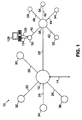
- a telecommunications network 10 for providing communications between a primary terminal 12 and a plurality of secondary terminals 50-58, through remote nodes 30-38 is shown in Fig. 1.
- the primary terminal 12 is connected to the remote nodes 30, 32, 34, 36, and 38 via waveguide loops 20, 22, 24, 26, and 28, respectively.
- the remote node 38 is further shown connected to secondary terminals 50, 52, 54, 56, and 58 via waveguide loops 40, 42, 44, 46, and 48, respectively.
- Each remote node is preferably similarly connected to secondary terminals, which are not shown.
- the secondary terminal 50 is shown connected to a subscriber's device, such as a PC terminal 128 with a modem, via output line 124 and input line 126.
- the primary terminal 12 is also preferably connected to further parts of the telecommunications network 10 (not shown) via an input/output bus 14.
- the input/output bus 14 may be connected to a plurality of further primary terminals, remote nodes, secondary terminals or subscribers' devices.
- Each of the waveguide loops 20-28 and 40-48 may include one or more waveguides. Although a single waveguide can process both inputs and outputs, two waveguides are preferably provided for each of the waveguide loops 20-28 and 40-48, one being an input waveguide and the other being an output waveguide. Each waveguide loop is preferably an optical fiber loop, which is preferably includes both an input and an output optical fiber.
- the primary terminal 12 receives data from the input/output bus 14 and sends the data through the waveguide loop 28 to a remote node, such as the remote node 38, for example.
- the data is then sent by the remote node 38 to one or more of the appropriate secondary terminals 50-58, via waveguide loops 40-48, respectively.
- the secondary terminals 50-58 are each preferably connected to one or more subscribers' devices, only one of which, the personal computer 128, is shown connected to the secondary terminal 50 by the output line 124 and the input line 126.
- the subscribers' devices may be of any type, including telephones, data terminals, and video terminals.
- Data is sent from the secondary terminal 50 to the remote node 38 via the waveguide loop 40 and is subsequently sent to the primary terminal 12 via the waveguide loop 28.
- the data is subsequently sent to further parts of the telecommunications network 10 via input/output bus 14.
- the data can be of any type, including voice, video, and computer digital signals.
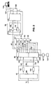
- Fig. 2 is a schematic showing one embodiment of detailed circuitry suitable for implementation of the primary terminal 12, the remote node 38, and the secondary terminal 50 in accordance with the present invention.
- the primary terminal 12 comprises a processor 100, a transmitter 102, and a receiver 104.
- the remote node 38 comprises a space division photonic switch 105 comprised of a downstream switch 106 and an upstream switch 108.
- the photonic switch 105 is preferably an electrically controlled optical switch and can be a space-division photonic switch as disclosed in K. Padmanabhan and A.N. Netravali, "Dilated Networks for Photonic Switching", IEEE Trans. on Comm. Vol. Com-35, pp. 1357-1365; December 1987.
- Each waveguide loop is preferably a fiber optic loop and the signals sent through the waveguide loops are preferably optical signals.
- the primary terminal is preferably a central office and the secondary terminals are preferably optical network units.
- the secondary terminal 50 comprises a first circuit 114 which is comprised of a splitter 116, a modulator 118, and a detector 120.
- the splitter 116, modulator 118, and detector 120 may be integrated into a single device if desired.
- the secondary terminal 50 also comprises a processor 122.
- the input/output bus 14 is connected to the processor 100 of primary terminal 12.
- the processor 100 is connected to the transmitter 102 and to the receiver 104.
- the transmitter 102 is connected to the downstream switch 106 of the remote node 38 via the output waveguide 101 of the waveguide loop 28.
- the receiver 104 is connected to the upstream switch 108 of the remote node 38 via the input waveguide 103 of the waveguide loop 28.
- the downstream switch 106 and the upstream switch 108 are connected to a control network 107, which is connected to a power supply 109.
- the power can also be derived from, for example, the waveguide loop 28 or the waveguide loop 40.
- the control network 107 may be connected to the output waveguide 101 or the control network 107 may include a wireless device for communicating directly with the primary terminal 12.
- the control network 107 may also be a part of a larger control network.
- the control network 107 may also receive status information from downstream switch 106 or upstream switch 108 to control the switches in any manner known in the art.
- the remote node 38 is connected to the secondary terminals 50-58 via the waveguide loops 40-48, respectively. More specifically, the downstream switch 106 is connected via the input waveguides to the secondary terminals 50-58 and the upstream switch 108 is connected via the output waveguides to the secondary terminals 50-58. For example, the downstream switch 106 is connected via the input waveguide 110 to the splitter 116 of the secondary terminal 50 and the upstream switch 108 is connected via the output waveguide 112 to the modulator 118 of the secondary terminal 50.
- the other secondary terminals 52-58 are connected in a similar manner to the remote node 38 and have similar components as the secondary terminal 50.
- the splitter 116 is connected to the modulator 118 and to the detector 120, at first and second outputs of the splitter 116 respectively.
- the output of the modulator 118 is connected to the upstream switch 108 via the output waveguide 112.
- the detector 120 is connected to the processor 122.
- the processor 122 has a plurality of output lines, such as output line 124, and a plurality of input lines, such as input line 126, which are connected to a plurality of subscribers' devices, although only one device, the PC terminal 128, is shown connected to output line 124 and input line 126.
- the processor may include a single output line or input line connected to a single subscriber.
- an input data signal is received by the primary terminal 12 from another part of the telecommunications network 10 via the input/output bus 14.
- the other part of the telecommunications network 10 may include further primary terminals, remote nodes, secondary terminals, and subscribers' devices.
- the input data signal is received by the processor 100 the primary terminal 12 and a time multiplexed electrical input data signal is sent to the transmitter 102.
- the transmitter 102 preferably modifies the electrical input data signal by changing it to a transport input data signal, which is preferably an optical signal.
- the transport input data signal from transmitter 102 is sent to the downstream switch 106.
- the downstream switch 106 is set by a control signal from the control network 107, in a known fashion. If, for example, the control signal has set the downstream switch 106 to input waveguide 110 of the secondary terminal 50, the transport input data signal appearing at the input of the downstream switch 106 is sent to the input waveguide 110 of the secondary terminal 50.
- the control signal can be derived from a separate source, from signals sent via waveguide loop 28, or via wireless signals sent to the remote node 38.
- the control signal can be provided as a function of time. If optical signals are transmitted by the transmitter 102, a portion of the optical signal received by the remote node 38 may be processed to form a control signal.
- the control signals should be synchronized with the transport input data signals, in a manner known in the art.
- the transport input data signal appearing on the input waveguide 110 is received and split into two portions by the splitter 116 of the secondary terminal 50.
- a first portion of the transport input data signal is sent to the modulator 118, while a second portion of the transport input data signal is sent to the detector 120.
- the modulator 118 impresses data received from the processor 122 on the first portion of the transport input data signal, to form an output data signal, which is sent back to the primary terminal 12 via the upstream switch 108.
- the upstream switch 108 of the remote node 38 connects an output waveguide, such as output waveguide 112 of the secondary terminal 50, to the input waveguide 103 of the primary terminal 12, in response to a control signal from the control network 107, in a known manner.
- the detector 120 at the secondary terminal 50 preferably changes the transport input data signal, which is preferably an optical data signal, to an electrical input data signal and sends the electrical input data signal to the processor 122.
- the processor 122 sends the electrical input data signal out to one of its subscriber output lines, such as output line 124.
- the electrical input data signal may alternatively be sent in another form to the processor 122, such as by wireless communication or through a waveguide.
- a subscriber's device such as the PC terminal 128, can input data to the processor 122 via the appropriate input line, in this case input line 126.
- the subscriber input data is sent to the modulator 118 and used to impress output data upon a portion of a transport input data signal received via the downstream switch 106 at the secondary terminal 50.
- the primary terminal 12 and the secondary terminal 50 are preferably a central office and an optical network unit, respectively.
- the waveguide loops of Fig. 2 are preferably optical fiber loops and each waveguide is preferably an optical fiber.
- the transmitter 102 and receiver 104 are preferably an optical transmitter and an optical receiver, respectively.
- the downstream switch 106 need not be connected to the same secondary terminal as the upstream switch 108 at the same time.
- the two switches should be connected independently to provide the most efficient switching. The most efficient switching may depend on distance of the appropriate secondary terminals from the remote node and the type and duration of the traffic.
- the transmitter 102 may be replaced by a plurality of transmitters, sending, for example, optical signals of different wavelengths down the output waveguide 101.
- the splitter 116 may split a transport input data signal by differences in time, wavelength, sub-carrier frequency, or in any other manner known in the art.
- the modulator 118 may be supplemented by a coupler and a signal source so that the output signal from secondary terminal 50 comprises a feed back portion of a transport input data signal and an independent source signal.
- the present invention provides communications between a primary terminal 12 and a plurality of secondary terminals through a plurality of remote nodes, where each remote node is preferably similar to the remote node 38.
- each remote node is preferably similar to the remote node 38.
- the embodiment of Fig. 2 described communications with other parts of the telecommunications network of Fig. 1 via input/output bus 14, the present invention may also provide communications from any remote node to any other remote node, for example, from remote node 38 to remote node 32, of Fig. 1.
Landscapes
- Engineering & Computer Science (AREA)
- Computer Networks & Wireless Communication (AREA)
- Optical Communication System (AREA)
- Telephonic Communication Services (AREA)
- Data Exchanges In Wide-Area Networks (AREA)
- Sub-Exchange Stations And Push- Button Telephones (AREA)
- Use Of Switch Circuits For Exchanges And Methods Of Control Of Multiplex Exchanges (AREA)
Applications Claiming Priority (2)
| Application Number | Priority Date | Filing Date | Title |
|---|---|---|---|
| US268427 | 1994-06-30 | ||
| US08/268,427 US5502587A (en) | 1994-06-30 | 1994-06-30 | Network comprising a space division photonic switch and a terminal which forms an output signal from an input signal |
Publications (1)
| Publication Number | Publication Date |
|---|---|
| EP0690651A2 true EP0690651A2 (de) | 1996-01-03 |
Family
ID=23022954
Family Applications (1)
| Application Number | Title | Priority Date | Filing Date |
|---|---|---|---|
| EP95304334A Withdrawn EP0690651A2 (de) | 1994-06-30 | 1995-06-21 | Netz mit optischer Raumkoppelanordnung und einem Endgerät |
Country Status (4)
| Country | Link |
|---|---|
| US (1) | US5502587A (de) |
| EP (1) | EP0690651A2 (de) |
| JP (1) | JPH0832523A (de) |
| CA (1) | CA2152416A1 (de) |
Cited By (2)
| Publication number | Priority date | Publication date | Assignee | Title |
|---|---|---|---|---|
| EP0831670A1 (de) * | 1996-09-20 | 1998-03-25 | Nippon Telegraph And Telephone Corporation | Telekommunikationsnetzwerk basierend auf verteilter Kontrolle |
| CN100386692C (zh) * | 2006-04-29 | 2008-05-07 | 中国科学院武汉物理与数学研究所 | 多通道光子开关 |
Families Citing this family (15)
| Publication number | Priority date | Publication date | Assignee | Title |
|---|---|---|---|---|
| US5680234A (en) * | 1994-10-20 | 1997-10-21 | Lucent Technologies Inc. | Passive optical network with bi-directional optical spectral slicing and loop-back |
| CA2262248A1 (en) | 1998-02-18 | 1999-08-18 | At&T Corp. | Long reach delivery of broadcast services using broadband optical sources and pre-compensation of dispersion |
| US6614781B1 (en) | 1998-11-20 | 2003-09-02 | Level 3 Communications, Inc. | Voice over data telecommunications network architecture |
| US7095957B1 (en) * | 2000-08-17 | 2006-08-22 | At&T Corp. | Optical/radio local access network |
| GB2371431A (en) * | 2001-01-20 | 2002-07-24 | Marconi Comm Ltd | Optical switch positioned between multi-wavelenth light sources and a plurality of modulators |
| US20090034965A1 (en) * | 2004-02-23 | 2009-02-05 | Look Christopher M | Method and an apparatus to automatically verify connectivity within an optical network node |
| US7848644B2 (en) * | 2004-02-23 | 2010-12-07 | Dynamic Method Enterprises Limited | Method and an apparatus to provide optical equipment protection |
| JP4909547B2 (ja) * | 2005-08-31 | 2012-04-04 | 日本電気通信システム株式会社 | 光スイッチ装置、光アクセスネットワーク、そのシステムおよび光波長多重伝送方法 |
| JP5051592B2 (ja) * | 2008-07-31 | 2012-10-17 | 学校法人慶應義塾 | 光ネットワークにおける回線制御方法及び光ネットワーク |
| US8532487B2 (en) * | 2008-10-21 | 2013-09-10 | Broadcom Corporation | Managed PON repeater and cross connect |
| WO2010050921A1 (en) * | 2008-10-31 | 2010-05-06 | Hewlett-Packard Development Company, L.P. | Prioritized optical arbitration systems and methods |
| US9794019B2 (en) | 2011-04-28 | 2017-10-17 | Hewlett Packard Enterprise Development Lp | Prioritized optical arbitration systems and methods |
| US11208188B2 (en) | 2019-06-10 | 2021-12-28 | Polaris Industries Inc. | Thruster arrangement for a boat |
| US12151798B2 (en) | 2019-09-27 | 2024-11-26 | Polaris Industries Inc. | System and method for positioning an aquatic vessel |
| US12179889B2 (en) | 2020-07-06 | 2024-12-31 | Polaris Industries Inc. | Boat maneuverability and stability control systems and methods |
Citations (1)
| Publication number | Priority date | Publication date | Assignee | Title |
|---|---|---|---|---|
| US2972493A (en) | 1959-02-13 | 1961-02-21 | Westinghouse Electric Corp | Means for attaching a knob or the like to a shaft |
Family Cites Families (10)
| Publication number | Priority date | Publication date | Assignee | Title |
|---|---|---|---|---|
| US3584220A (en) * | 1966-04-09 | 1971-06-08 | Hitachi Ltd | Optical communication system |
| US4946244A (en) * | 1984-08-24 | 1990-08-07 | Pacific Bell | Fiber optic distribution system and method of using same |
| US4730301A (en) * | 1985-12-20 | 1988-03-08 | Polaroid Corporation | Wavelength multiplexed optical communications system and method |
| US4879763A (en) * | 1986-02-21 | 1989-11-07 | AT&T Bell Laboratories American Telephone and Telegraph Company | Optical fiber bidirectional transmission system |
| US5058101A (en) * | 1988-12-15 | 1991-10-15 | Bell Communications Research, Inc. | Coherent detection loop distribution system |
| US5221983A (en) * | 1989-01-19 | 1993-06-22 | Bell Communications Research, Inc. | Passive photonic loop architecture employing wavelength multiplexing |
| US5073980A (en) * | 1989-08-29 | 1991-12-17 | The Trustees Of Princeton University | Photonic switch employing shared data transmission facility |
| US5212577A (en) * | 1990-01-19 | 1993-05-18 | Canon Kabushiki Kaisha | Optical communication equipment and optical communication method |
| FR2672172B1 (fr) * | 1991-01-29 | 1993-06-04 | Cit Alcatel | Matrice de commutation photonique. |
| US5347384A (en) * | 1992-06-30 | 1994-09-13 | Loral Aerospace Corp. | Fiber optic distribution of image data |
-
1994
- 1994-06-30 US US08/268,427 patent/US5502587A/en not_active Expired - Fee Related
-
1995
- 1995-06-21 EP EP95304334A patent/EP0690651A2/de not_active Withdrawn
- 1995-06-22 CA CA002152416A patent/CA2152416A1/en not_active Abandoned
- 1995-06-28 JP JP7183214A patent/JPH0832523A/ja active Pending
Patent Citations (1)
| Publication number | Priority date | Publication date | Assignee | Title |
|---|---|---|---|---|
| US2972493A (en) | 1959-02-13 | 1961-02-21 | Westinghouse Electric Corp | Means for attaching a knob or the like to a shaft |
Non-Patent Citations (1)
| Title |
|---|
| K. PADMANABHAN AND A.N. NETRAVALI: "Dilated Networks for Photonic Switching", IEEE TRANS. ON COMM., vol. COM-35, December 1987 (1987-12-01), pages 1357 - 1365, XP000820919, DOI: doi:10.1109/TCOM.1987.1096722 |
Cited By (3)
| Publication number | Priority date | Publication date | Assignee | Title |
|---|---|---|---|---|
| EP0831670A1 (de) * | 1996-09-20 | 1998-03-25 | Nippon Telegraph And Telephone Corporation | Telekommunikationsnetzwerk basierend auf verteilter Kontrolle |
| US6091734A (en) * | 1996-09-20 | 2000-07-18 | Nippon Telegraph And Telephone Corporation | Telecommunication network based on distributed control |
| CN100386692C (zh) * | 2006-04-29 | 2008-05-07 | 中国科学院武汉物理与数学研究所 | 多通道光子开关 |
Also Published As
| Publication number | Publication date |
|---|---|
| US5502587A (en) | 1996-03-26 |
| JPH0832523A (ja) | 1996-02-02 |
| CA2152416A1 (en) | 1995-12-31 |
Similar Documents
| Publication | Publication Date | Title |
|---|---|---|
| US5502587A (en) | Network comprising a space division photonic switch and a terminal which forms an output signal from an input signal | |
| KR100889899B1 (ko) | 비트 레이트 혼재 광통신 방법, 광가입자 장치 및 광국측장치 | |
| EP0512642B1 (de) | Optische Sende-Empfanganordnung | |
| US5202780A (en) | Optical communication system for the subscriber area | |
| US6445472B1 (en) | Optical fiber subscriber network | |
| EP0896448B1 (de) | Optisches Knotensystem für Ringarchitektur und zugehöriges Verfahren | |
| US4545048A (en) | Service integrated digital transmission system | |
| JP3169665B2 (ja) | 光増幅器を備えた加入者区域用光通信システム | |
| US7433594B2 (en) | Node apparatus, optical wavelength division multiplexing network, and system switching method | |
| EP1387511B1 (de) | Einheitliches passives Rundfunk-/Kommunikationsnetzwerk | |
| EP0720314A1 (de) | Eindimensionale optische Matrize für optisches Netz | |
| JPH0414531B2 (de) | ||
| US5212578A (en) | Selection of transmission facilities using optical wavelength division multiplexing | |
| US8824890B2 (en) | Open optical access network system | |
| WO2010009533A1 (en) | Wdm pon rf/video broadcast overlay | |
| CA1160771A (en) | Service integrated, digital transmission system | |
| AU623498B2 (en) | Optical subscriber loop system | |
| US5189544A (en) | Bidirectional light waveguide telecommunication system | |
| JP3533370B2 (ja) | 幹線ノード装置、及び光アクセスネットワーク | |
| US5668652A (en) | Optical WDM (wavelength division multiplexing) transmission system and method for configuring the same | |
| CN101964926B (zh) | 一种光信号传输方法和系统 | |
| WO1986005649A1 (en) | Optical networks | |
| JP2001251252A (ja) | 光アクセス網、幹線ノード装置及び支線ノード装置 | |
| JP2009141937A (ja) | 光学フィルタリング装置及び光通信システム | |
| NZ244538A (en) | Wavelength multiplexed optical network connection to subscriber terminals |
Legal Events
| Date | Code | Title | Description |
|---|---|---|---|
| PUAI | Public reference made under article 153(3) epc to a published international application that has entered the european phase |
Free format text: ORIGINAL CODE: 0009012 |
|
| AK | Designated contracting states |
Kind code of ref document: A2 Designated state(s): DE FR GB IT |
|
| STAA | Information on the status of an ep patent application or granted ep patent |
Free format text: STATUS: THE APPLICATION HAS BEEN WITHDRAWN |
|
| 18W | Application withdrawn |
Withdrawal date: 19971103 |