EP0690659A2 - Unité de cuisson à commande par infrarouge - Google Patents
Unité de cuisson à commande par infrarouge Download PDFInfo
- Publication number
- EP0690659A2 EP0690659A2 EP95109645A EP95109645A EP0690659A2 EP 0690659 A2 EP0690659 A2 EP 0690659A2 EP 95109645 A EP95109645 A EP 95109645A EP 95109645 A EP95109645 A EP 95109645A EP 0690659 A2 EP0690659 A2 EP 0690659A2
- Authority
- EP
- European Patent Office
- Prior art keywords
- sensor
- cooking
- hob
- infrared
- cooking unit
- Prior art date
- Legal status (The legal status is an assumption and is not a legal conclusion. Google has not performed a legal analysis and makes no representation as to the accuracy of the status listed.)
- Granted
Links
Images

Classifications
-
- H—ELECTRICITY
- H05—ELECTRIC TECHNIQUES NOT OTHERWISE PROVIDED FOR
- H05B—ELECTRIC HEATING; ELECTRIC LIGHT SOURCES NOT OTHERWISE PROVIDED FOR; CIRCUIT ARRANGEMENTS FOR ELECTRIC LIGHT SOURCES, IN GENERAL
- H05B1/00—Details of electric heating devices
- H05B1/02—Automatic switching arrangements specially adapted to apparatus ; Control of heating devices
- H05B1/0227—Applications
- H05B1/0252—Domestic applications
- H05B1/0258—For cooking
- H05B1/0261—For cooking of food
- H05B1/0266—Cooktops
-
- H—ELECTRICITY
- H05—ELECTRIC TECHNIQUES NOT OTHERWISE PROVIDED FOR
- H05B—ELECTRIC HEATING; ELECTRIC LIGHT SOURCES NOT OTHERWISE PROVIDED FOR; CIRCUIT ARRANGEMENTS FOR ELECTRIC LIGHT SOURCES, IN GENERAL
- H05B3/00—Ohmic-resistance heating
- H05B3/68—Heating arrangements specially adapted for cooking plates or analogous hot-plates
- H05B3/74—Non-metallic plates, e.g. vitroceramic, ceramic or glassceramic hobs, also including power or control circuits
- H05B3/746—Protection, e.g. overheat cutoff, hot plate indicator
-
- H—ELECTRICITY
- H05—ELECTRIC TECHNIQUES NOT OTHERWISE PROVIDED FOR
- H05B—ELECTRIC HEATING; ELECTRIC LIGHT SOURCES NOT OTHERWISE PROVIDED FOR; CIRCUIT ARRANGEMENTS FOR ELECTRIC LIGHT SOURCES, IN GENERAL
- H05B2213/00—Aspects relating both to resistive heating and to induction heating, covered by H05B3/00 and H05B6/00
- H05B2213/07—Heating plates with temperature control means
Definitions
- the invention relates to an infrared sensor-controlled cooking unit, consisting of a cooking device, sensors and hob, for example a glass ceramic hob, where both the hob and the cooking device can contain sensor-specific configurations.
- Heating processes in particular cooking processes in cooking appliances on hobs, can take place automatically if the temperature of the food to be cooked is sufficiently well measurable during the heating process.
- the progress of the cooking process can be inferred from such temperature profiles.
- the temperature of the cookware base or a cookware wall largely corresponds to the temperature of the food when the cooking process has exceeded the heating phase.
- thermocouple chain For higher temperatures, such as occur during roasting and deep-frying, platinum sensors have been arranged under, for example, glass ceramic cooktops, with which a sufficiently good temperature measurement can be carried out in the steady state of the cooking process.
- the object of the present invention is to construct an infrared sensor-controlled cooking unit, with which the temperature of the food to be cooked can be measured with sufficient accuracy in a simple and reliable manner.
- an infrared sensor associated with the sensor-controlled cooking unit is arranged slightly elevated above the hob in relation to the cooking point. This allows the wall temperature of the cooking device to be measured conveniently and relatively accurately by the infrared sensor.
- the infrared sensor is arranged in a design-specific, predominantly peripheral manner, opposite the operator front, flush with the glass ceramic cooking surface and is functionally coupled to the electronics unit of the charging unit.
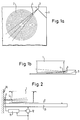
- FIGS. 1a, b a cooking device 1, a cooktop 2, a sensor, here infrared sensor 3, a sensor measuring spot 4 on the cooking device 1 and a sensor housing structure 8 can be seen.
- the infrared sensor 3 assigned to the sensor-controlled cooking unit is arranged slightly elevated above the hob in relation to the cooking point. This installation of the infrared sensor in a hob is advisable if the design line of the hob can tolerate a sensor arrangement installed one to two cm above the glass ceramic.
- the infrared sensor-monitored hotplates on the respective hob are preferably those located in the immediate vicinity of the slightly elevated design line of the hob.
- an infrared transmitter is conceivable, which is arranged in a retractable or foldable unit, which will protrude about 2 cm above the hob 2 in the functional state, whereby it would be conceivable that the infrared sensors could be moved out of the oven by an easily operated pressure device Surface of the glass ceramic cooktop can be clipped out.
- the infrared sensor can always be assigned to the hotplate that is to be controlled.
- the connection to the electronics of the hob or to the control electronics that control the respective power relay can be wired, radio-oriented or in another electronic manner. Such systems can be implemented for induction, radiation and halogen cookers.
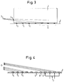
- the cooking appliance 1, the glass ceramic cooking surface 2, the sensor measuring spot 4 on the cooking appliance 1, a sensor arrangement 9, a wall 10 assigned to the cooking surface, an electronic module 11, a power relay 12 and a worktop 13 can be seen.
- the infrared sensor 3 is arranged slightly elevated above and outside the cooking surface 2, for example on devices of the adjacent stove wall 10.
- the infrared sensor 3 can also be installed in a piece of wiper strip or a special housing for wall mounting become. Such a construction does not require any special space and protects the sensor against damage.
- the infrared sensors used here in the cooking units presented receive the infrared radiation from the walls of the cookware under the effect of a concave mirror integrated in the sensor system.
- the infrared sensor is usually protected against mechanical damage or precipitation of vapor condensate by an infrared filter made of silicon.
- Such sensors only have a volume of approx. 2 ccm. Therefore, they can be sensibly and practically installed on the hob or built into it or arranged in the vicinity. 2 such a sensor is arranged in the wall area opposite the hob. Starting from the measuring spot 4 on the cooking device 1, the infrared signal the radiating side wall of the cooking device 1 received by the infrared transmitter 3 in the arrangement position 9. It is advisable to arrange the sensor in such a way that infrared radiation from the controlled hotplate on hob 2 could be received if the pan was not placed on it.
- the cooktop 2 in particular a glass ceramic cooktop, has decor printing 6 that is suitable for infrared sensors, whereby the infrared sensor 3 can detect that the monitored hotplate is idling. It has proven to be expedient to carry out the decor printing on the hob 2 in the manner of a hill.
- the cooking device 1 associated with the sensor-controlled cooking unit must be suitable for infrared sensors; for most cookware that does not consist of stainless steel or glass in the household, the infrared sensor is suitable.
- the wall temperature of cookware made of stainless steel or glass cannot be measured with infrared sensors in the original state, since stainless steel, especially in the polished version, and glass have very low infrared emission factors, but have very high infrared reflection factors.
- the infrared rays emanating from the cooking appliance 1 or the hob surface 2 to the infrared sensor 3 are shown.
- the measuring spots 4 on the cooking device 1 and the various measuring spots on the respective hotplate are recognizable and, furthermore, a possibility is indicated how infrared radiation from heating element 7 with an open hotplate, ie hotplate without a pot, can be used for idle detection.
- the infrared sensor Since the infrared sensor has a direction-dependent sensitivity, the infrared sensor looks at the glass ceramic cooktop or another cooktop at a very flat angle, and can therefore hardly recognize the temperature of the hotplate on the cooktop.
- the cooktop 2 is covered by the cookware or cooking appliance 1 to be heated, so the hotplate can hardly influence the signal from the sensor. If there is no cooking appliance 1 on the hotplate, ie the hotplate is running empty, then the infrared sensor can detect the temperature of a sector of the hotplate on the hob 2 with a suitable orientation. In this way, an idle case can be recognized by suitable evaluation of the infrared signal and a power supply can be limited or completely prevented by controlling an electronic module with subsequent power control by a relay 12.
- the infrared sensor responds particularly well when the decor printing of the cooktop glass ceramic is in the form of small hills, since in this way the infrared sensor is given a better viewing angle on the hot glass ceramic surface.
- infrared light refraction under, in and / or on the glass ceramic.
- a small part of the infrared radiation generated by radiation or halogen cookers can thus be directed directly in the direction of the infrared sensor. If a cookware is on the glass ceramic, then this infrared beam is interrupted by the cookware, the hotplate is then only regulated by the temperature of the cookware.
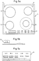
- a sensor-controlled cooking unit can be recognized as a sensor-equipped glass ceramic hob 14, retractable sensor units 21, hotplates 31 to 34 and an operating front 51.
- FIGS. 5b and 5c show a detail of the retractable sensor unit 12.
- FIG. 5c shows a detail of the control front 51.
- This detail of the control front 51 shows that the operator can, for example, key in more than four basic functions, wherein he couples the retractable sensor unit to the electronics unit.
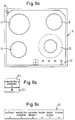
- Figure 6a shows hardly any significant changes compared to Figure 5a, apart from the design of the retractable sensor unit 22, which can either be left-justified on the outer edge of the glass ceramic cooking surface or right-justified opposite.
- the sensor switch 12 is made in two parts. It consists of the sensor-specific monitoring part 13.1 and a cooking mode selector arrangement according to 12.1, by means of which it is possible for the operator to select basic functions in the manner shown.
- Basic functions are types of cooking that are used very often.
- Figure 6c offers the five to six essential types of basic cooking at. As a cooking function, these are keeping warm or heating, cooking or simmering, cooking, frying, steaming. Thawing is offered as a special function, whereby the sensor is relatively unsafe in the lower temperature ranges, but cannot be used beyond its functions.
- the sensor switch 12 works directly with the electronics unit of the cooking unit.
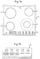
- Figures 7a, b differ from the technical details derived according to Figure 5a only in design. This relates in particular to the arrangement of the retractable sensor unit, which is provided here with a special, centrally arranged, semicircular sensor installation unit 23. In this sensor unit 23, which can also be retracted or folded down, there are at least two infrared sensors which enable the hotplates 31 and 32 to be reliably detected. Under special placement instructions for pots and their size on the glass ceramic hob 14 according to FIG. 7a, three or even four infrared sensors can also be installed under the sensor unit 23. It is important that a clear assignment of the placed sensor and monitored hotplate is possible.
- Figure 7b corresponds to the content of Figure 5c and is therefore largely identical.
- FIGS. 8a, b, c a special embodiment of the sensor-controlled cooking unit 14, ie the glass ceramic cooktop with sensor arrangement, can be removed compared to the previous exemplary embodiments.
- 8a shows a rectangular glass ceramic cooktop which is elongated from the operator's point of view, on which the hotplates 31, 32, 33 and 34 are arranged essentially linearly adjacent.
- the retractable sensor unit 24 is arranged in a retractable manner in four ways, related to the cooking point, on the rear edge of the glass ceramic cooking surface.
- the operation and selection of the types of food correspond to those stated in FIGS. 5b and 5c.
- the particular embodiment of the sensor-controlled cooking unit according to FIG. 8a, ie the design of the glass ceramic cooktop with a sensor arrangement enables the sensor unit 21 to be uniquely assigned to the respective hotplate to be monitored. In the exemplary embodiment, all hotplates are monitored by sensors, which of course can be varied in any way.
- the infrared sensor is arranged in a design-specific manner, predominantly peripherally, opposite the operator front, flush with the glass ceramic cooking surface 14 and is functionally coupled to the electronics unit of the cooking unit.
- the infrared sensor on the left or right outer edge of the glass ceramic cooking surface 14 is arranged so that it is opposite the operator front, and that at least one sensor unit has two to a maximum of four sensor units per glass ceramic cooking surface are positionable.
- the sensor units could be arranged around the circumference of the glass ceramic hob 14.
- a special feature for monitoring at least two hotplates is an infrared sensor receptacle 23 arranged centrally on the rear edge of the glass ceramic cooktop, the infrared sensor receptacle 23 having a semicircular lens shape.
- typical cooking methods that the sensor-controlled cooking unit implements can also be selected on the control element for the infrared sensor. It would be considered typical that a control element on the control front is activated with the sensor connection, whereby the sensor-controlled cooking unit 14 is connected to the hob control and typical cooking methods can be selected by the operator.
- infrared light refraction under, in and / or on the glass ceramic. This allows a small part of the infrared radiation generated by the radiation or halogen cooker to be directed directly in the direction of the infrared sensor. If a cookware is on ceramic glass, this infrared beam is interrupted by the cookware, the hotplate is then only regulated by the temperature of the cookware.
- a cooking unit controlled with infrared sensor technology advantageously has good control constancy of the cooking process.
- the infrared sensor can be positioned cheaply or in the hob, that it is possible to position the infrared sensor in the vicinity of the hob, that conventional stainless steel and glass cooking appliances can also be processed by coating with infrared sensors and that the infrared sensor signal can also provide idle detection of the glass ceramic hob in addition to the sensor-controlled cooking.
Landscapes
- Engineering & Computer Science (AREA)
- Chemical & Material Sciences (AREA)
- Ceramic Engineering (AREA)
- Food Science & Technology (AREA)
- Electric Stoves And Ranges (AREA)
- Surface Treatment Of Glass (AREA)
- Electric Ovens (AREA)
Priority Applications (1)
| Application Number | Priority Date | Filing Date | Title |
|---|---|---|---|
| DE29522310U DE29522310U1 (de) | 1994-06-27 | 1995-06-21 | Infrarotgesteuerte Garungseinheit |
Applications Claiming Priority (4)
| Application Number | Priority Date | Filing Date | Title |
|---|---|---|---|
| DE19944422354 DE4422354A1 (de) | 1994-06-27 | 1994-06-27 | Infrarotgesteuerte Garungseinheit |
| DE4422354 | 1994-06-27 | ||
| DE29506244U | 1995-04-11 | ||
| DE29506244U DE29506244U1 (de) | 1995-04-11 | 1995-04-11 | Infrarotgesteuerte Garungseinheit |
Publications (3)
| Publication Number | Publication Date |
|---|---|
| EP0690659A2 true EP0690659A2 (fr) | 1996-01-03 |
| EP0690659A3 EP0690659A3 (fr) | 1996-05-22 |
| EP0690659B1 EP0690659B1 (fr) | 2001-11-28 |
Family
ID=25937740
Family Applications (1)
| Application Number | Title | Priority Date | Filing Date |
|---|---|---|---|
| EP95109645A Expired - Lifetime EP0690659B1 (fr) | 1994-06-27 | 1995-06-21 | Unité de cuisson à commande par infrarouge |
Country Status (3)
| Country | Link |
|---|---|
| EP (1) | EP0690659B1 (fr) |
| DE (1) | DE59509878D1 (fr) |
| ES (1) | ES2170110T3 (fr) |
Cited By (20)
| Publication number | Priority date | Publication date | Assignee | Title |
|---|---|---|---|---|
| WO1997035455A1 (fr) * | 1996-03-20 | 1997-09-25 | Ventura Vale Lato | Systeme d'exploitation de la surface totale vitroceramique de cuisine |
| WO1998021916A1 (fr) * | 1996-11-14 | 1998-05-22 | Timer-Clock Hl Ab | Dispositif pour unite de surveillance pour objets diffusant la chaleur |
| FR2809480A1 (fr) * | 2000-05-24 | 2001-11-30 | Seb Sa | Appareil destine au chauffage d'un fluide tel que notamment de la cire epilatoire |
| US6461573B1 (en) | 1997-10-03 | 2002-10-08 | Mitsui Chemicals, Inc. | Fluidized bed polymerization apparatus having temperature distribution monitoring |
| DE10141754A1 (de) * | 2001-08-29 | 2003-04-03 | Aeg Hausgeraete Gmbh | Verfahren und Vorrichtung zum Steuern eines Gargerätes, insbesondere Haushaltsgargerätes |
| EP2653785A1 (fr) * | 2012-04-16 | 2013-10-23 | Whirlpool Corporation | Signaux lumineux afin de fournir une direction à un utilisateur |
| DE202017006001U1 (de) | 2017-11-20 | 2018-02-19 | Adriano Albrecht | Grillgut-Aufnahme mit integrierten Sensoren |
| EP3336436A1 (fr) * | 2016-12-19 | 2018-06-20 | Electrolux Appliances Aktiebolag | Table de cuisson dotée d'un dispositif de surveillance |
| US10145568B2 (en) | 2016-06-27 | 2018-12-04 | Whirlpool Corporation | High efficiency high power inner flame burner |
| USD835775S1 (en) | 2015-09-17 | 2018-12-11 | Whirlpool Corporation | Gas burner |
| IT201800004418A1 (it) * | 2018-04-12 | 2019-10-12 | Piano a induzione a cottura automatica | |
| US10451290B2 (en) | 2017-03-07 | 2019-10-22 | Whirlpool Corporation | Forced convection steam assembly |
| US10551056B2 (en) | 2017-02-23 | 2020-02-04 | Whirlpool Corporation | Burner base |
| US10619862B2 (en) | 2018-06-28 | 2020-04-14 | Whirlpool Corporation | Frontal cooling towers for a ventilation system of a cooking appliance |
| US10627116B2 (en) | 2018-06-26 | 2020-04-21 | Whirlpool Corporation | Ventilation system for cooking appliance |
| US10660162B2 (en) | 2017-03-16 | 2020-05-19 | Whirlpool Corporation | Power delivery system for an induction cooktop with multi-output inverters |
| US10837652B2 (en) | 2018-07-18 | 2020-11-17 | Whirlpool Corporation | Appliance secondary door |
| US10837651B2 (en) | 2015-09-24 | 2020-11-17 | Whirlpool Corporation | Oven cavity connector for operating power accessory trays for cooking appliance |
| US11777190B2 (en) | 2015-12-29 | 2023-10-03 | Whirlpool Corporation | Appliance including an antenna using a portion of appliance as a ground plane |
| EP4294125A1 (fr) * | 2022-06-17 | 2023-12-20 | Whirlpool Corporation | Table de cuisson à induction à détection de température ir et point transparent |
Family Cites Families (2)
| Publication number | Priority date | Publication date | Assignee | Title |
|---|---|---|---|---|
| US3636309A (en) * | 1970-11-19 | 1972-01-18 | Gen Motors Corp | Ceramic-top cooking assembly fracture detector |
| US5212763A (en) * | 1992-09-11 | 1993-05-18 | Gte Products Corporation | Electric fluid heater with infrared hot spot sensor |
-
1995
- 1995-06-21 ES ES95109645T patent/ES2170110T3/es not_active Expired - Lifetime
- 1995-06-21 EP EP95109645A patent/EP0690659B1/fr not_active Expired - Lifetime
- 1995-06-21 DE DE59509878T patent/DE59509878D1/de not_active Expired - Lifetime
Non-Patent Citations (1)
| Title |
|---|
| None |
Cited By (29)
| Publication number | Priority date | Publication date | Assignee | Title |
|---|---|---|---|---|
| ES2115525A1 (es) * | 1996-03-20 | 1998-06-16 | Lato Ventura Vale | Sistema de aprovechamiento de la superficie total de vitroceramica para cocina. |
| WO1997035455A1 (fr) * | 1996-03-20 | 1997-09-25 | Ventura Vale Lato | Systeme d'exploitation de la surface totale vitroceramique de cuisine |
| WO1998021916A1 (fr) * | 1996-11-14 | 1998-05-22 | Timer-Clock Hl Ab | Dispositif pour unite de surveillance pour objets diffusant la chaleur |
| US6461573B1 (en) | 1997-10-03 | 2002-10-08 | Mitsui Chemicals, Inc. | Fluidized bed polymerization apparatus having temperature distribution monitoring |
| US6897268B2 (en) | 1997-10-03 | 2005-05-24 | Mitsui Chemical, Inc. | Fluidized bed polymerization apparatus and an olefin polymerization process |
| FR2809480A1 (fr) * | 2000-05-24 | 2001-11-30 | Seb Sa | Appareil destine au chauffage d'un fluide tel que notamment de la cire epilatoire |
| WO2001090654A3 (fr) * | 2000-05-24 | 2002-04-04 | Seb Sa | Appareil destine au chauffage d'un fluide tel que notamment de la cire epilatoire |
| DE10141754A1 (de) * | 2001-08-29 | 2003-04-03 | Aeg Hausgeraete Gmbh | Verfahren und Vorrichtung zum Steuern eines Gargerätes, insbesondere Haushaltsgargerätes |
| EP2653785A1 (fr) * | 2012-04-16 | 2013-10-23 | Whirlpool Corporation | Signaux lumineux afin de fournir une direction à un utilisateur |
| USD835775S1 (en) | 2015-09-17 | 2018-12-11 | Whirlpool Corporation | Gas burner |
| US10837651B2 (en) | 2015-09-24 | 2020-11-17 | Whirlpool Corporation | Oven cavity connector for operating power accessory trays for cooking appliance |
| US11460195B2 (en) | 2015-09-24 | 2022-10-04 | Whirlpool Corporation | Oven cavity connector for operating power accessory trays for cooking appliance |
| US11777190B2 (en) | 2015-12-29 | 2023-10-03 | Whirlpool Corporation | Appliance including an antenna using a portion of appliance as a ground plane |
| US10145568B2 (en) | 2016-06-27 | 2018-12-04 | Whirlpool Corporation | High efficiency high power inner flame burner |
| WO2018114137A1 (fr) * | 2016-12-19 | 2018-06-28 | Electrolux Appliances Aktiebolag | Plaque de cuisson dotée d'un dispositif de surveillance |
| EP3336436A1 (fr) * | 2016-12-19 | 2018-06-20 | Electrolux Appliances Aktiebolag | Table de cuisson dotée d'un dispositif de surveillance |
| US10551056B2 (en) | 2017-02-23 | 2020-02-04 | Whirlpool Corporation | Burner base |
| US10451290B2 (en) | 2017-03-07 | 2019-10-22 | Whirlpool Corporation | Forced convection steam assembly |
| US10660162B2 (en) | 2017-03-16 | 2020-05-19 | Whirlpool Corporation | Power delivery system for an induction cooktop with multi-output inverters |
| DE202017006001U1 (de) | 2017-11-20 | 2018-02-19 | Adriano Albrecht | Grillgut-Aufnahme mit integrierten Sensoren |
| IT201800004418A1 (it) * | 2018-04-12 | 2019-10-12 | Piano a induzione a cottura automatica | |
| US10627116B2 (en) | 2018-06-26 | 2020-04-21 | Whirlpool Corporation | Ventilation system for cooking appliance |
| US11226106B2 (en) | 2018-06-26 | 2022-01-18 | Whirlpool Corporation | Ventilation system for cooking appliance |
| US12140315B2 (en) | 2018-06-26 | 2024-11-12 | Whirlpool Corporation | Ventilation system for cooking appliance |
| US12560335B2 (en) | 2018-06-26 | 2026-02-24 | Whirlpool Corporation | Ventilation system for cooking appliance |
| US11137145B2 (en) | 2018-06-28 | 2021-10-05 | Whirlpool Corporation | Frontal cooling towers for a ventilation system of a cooking appliance |
| US10619862B2 (en) | 2018-06-28 | 2020-04-14 | Whirlpool Corporation | Frontal cooling towers for a ventilation system of a cooking appliance |
| US10837652B2 (en) | 2018-07-18 | 2020-11-17 | Whirlpool Corporation | Appliance secondary door |
| EP4294125A1 (fr) * | 2022-06-17 | 2023-12-20 | Whirlpool Corporation | Table de cuisson à induction à détection de température ir et point transparent |
Also Published As
| Publication number | Publication date |
|---|---|
| ES2170110T3 (es) | 2002-08-01 |
| EP0690659B1 (fr) | 2001-11-28 |
| EP0690659A3 (fr) | 1996-05-22 |
| DE59509878D1 (de) | 2002-01-10 |
Similar Documents
| Publication | Publication Date | Title |
|---|---|---|
| EP0690659B1 (fr) | Unité de cuisson à commande par infrarouge | |
| EP1006756B2 (fr) | Régulateur de plaque chauffante à l'aide d'un détecteur situé en dessous de la plaque | |
| EP2024686B1 (fr) | Appareil ménager, de préférence plaque de cuisson | |
| EP1217873B1 (fr) | Procédé et dispositif de détection de la température d'un ustensile de cuisine | |
| EP0990855B2 (fr) | Plaque de cuisson à temporisation encastrée | |
| EP0967839A2 (fr) | Plaque de cuisson munie d'une unité de commande dans le but de déterminer le niveau de puissance fournie | |
| DE4422354A1 (de) | Infrarotgesteuerte Garungseinheit | |
| DE69938112T2 (de) | Kochgerät | |
| EP0658067A1 (fr) | Commande pour l'évaluation des signaux des capteurs d'un appareil électro-ménager | |
| EP2775792B1 (fr) | Appareil de cuisson | |
| DE29522310U1 (de) | Infrarotgesteuerte Garungseinheit | |
| DE10242099A1 (de) | Kochfeld | |
| EP2775788B1 (fr) | Appareil de cuisson | |
| EP2775784B1 (fr) | Dispositif de cuisson et procédé de fonctionnement | |
| EP2775789B1 (fr) | Dispositif de cuisson et procédé de montage | |
| EP0621739A2 (fr) | Système de cuisson | |
| DE3928620A1 (de) | Kochherd mit steuerung der energiezufuhr | |
| EP2775787A1 (fr) | Appareil de cuisson | |
| EP3031297B1 (fr) | Équipement de cuisson et méthode pour contrôler ledit équipement | |
| EP2775786B1 (fr) | Appareil de cuisson | |
| EP2775790A1 (fr) | Appareil de cuisson | |
| DE19932142A1 (de) | Koch-, Back- oder Grillgerät | |
| DE29506244U1 (de) | Infrarotgesteuerte Garungseinheit | |
| WO2015018890A1 (fr) | Dispositif de cuisson et son procédé de fonctionnement | |
| EP2775791B1 (fr) | Appareil de cuisson |
Legal Events
| Date | Code | Title | Description |
|---|---|---|---|
| PUAI | Public reference made under article 153(3) epc to a published international application that has entered the european phase |
Free format text: ORIGINAL CODE: 0009012 |
|
| AK | Designated contracting states |
Kind code of ref document: A2 Designated state(s): DE ES FR GB IT |
|
| PUAL | Search report despatched |
Free format text: ORIGINAL CODE: 0009013 |
|
| AK | Designated contracting states |
Kind code of ref document: A3 Designated state(s): DE ES FR GB IT |
|
| 17P | Request for examination filed |
Effective date: 19961024 |
|
| RAP1 | Party data changed (applicant data changed or rights of an application transferred) |
Owner name: BSH BOSCH UND SIEMENS HAUSGERAETE GMBH |
|
| GRAG | Despatch of communication of intention to grant |
Free format text: ORIGINAL CODE: EPIDOS AGRA |
|
| 17Q | First examination report despatched |
Effective date: 20010115 |
|
| GRAG | Despatch of communication of intention to grant |
Free format text: ORIGINAL CODE: EPIDOS AGRA |
|
| GRAH | Despatch of communication of intention to grant a patent |
Free format text: ORIGINAL CODE: EPIDOS IGRA |
|
| GRAH | Despatch of communication of intention to grant a patent |
Free format text: ORIGINAL CODE: EPIDOS IGRA |
|
| GRAH | Despatch of communication of intention to grant a patent |
Free format text: ORIGINAL CODE: EPIDOS IGRA |
|
| GRAA | (expected) grant |
Free format text: ORIGINAL CODE: 0009210 |
|
| AK | Designated contracting states |
Kind code of ref document: B1 Designated state(s): DE ES FR GB IT |
|
| GBT | Gb: translation of ep patent filed (gb section 77(6)(a)/1977) |
Effective date: 20011128 |
|
| REG | Reference to a national code |
Ref country code: GB Ref legal event code: IF02 |
|
| REF | Corresponds to: |
Ref document number: 59509878 Country of ref document: DE Date of ref document: 20020110 |
|
| ET | Fr: translation filed | ||
| REG | Reference to a national code |
Ref country code: ES Ref legal event code: FG2A Ref document number: 2170110 Country of ref document: ES Kind code of ref document: T3 |
|
| PLBE | No opposition filed within time limit |
Free format text: ORIGINAL CODE: 0009261 |
|
| STAA | Information on the status of an ep patent application or granted ep patent |
Free format text: STATUS: NO OPPOSITION FILED WITHIN TIME LIMIT |
|
| 26N | No opposition filed | ||
| PGFP | Annual fee paid to national office [announced via postgrant information from national office to epo] |
Ref country code: IT Payment date: 20120623 Year of fee payment: 18 |
|
| PG25 | Lapsed in a contracting state [announced via postgrant information from national office to epo] |
Ref country code: IT Free format text: LAPSE BECAUSE OF NON-PAYMENT OF DUE FEES Effective date: 20130621 |
|
| PGFP | Annual fee paid to national office [announced via postgrant information from national office to epo] |
Ref country code: GB Payment date: 20140620 Year of fee payment: 20 |
|
| PGFP | Annual fee paid to national office [announced via postgrant information from national office to epo] |
Ref country code: ES Payment date: 20140618 Year of fee payment: 20 Ref country code: DE Payment date: 20140630 Year of fee payment: 20 |
|
| PGFP | Annual fee paid to national office [announced via postgrant information from national office to epo] |
Ref country code: FR Payment date: 20140617 Year of fee payment: 20 |
|
| REG | Reference to a national code |
Ref country code: DE Ref legal event code: R081 Ref document number: 59509878 Country of ref document: DE Owner name: BSH HAUSGERAETE GMBH, DE Free format text: FORMER OWNER: BSH BOSCH UND SIEMENS HAUSGERAETE GMBH, 81739 MUENCHEN, DE Effective date: 20150408 |
|
| REG | Reference to a national code |
Ref country code: ES Ref legal event code: PC2A Owner name: BSH HAUSGERATE GMBH Effective date: 20150527 |
|
| REG | Reference to a national code |
Ref country code: DE Ref legal event code: R071 Ref document number: 59509878 Country of ref document: DE |
|
| REG | Reference to a national code |
Ref country code: GB Ref legal event code: PE20 Expiry date: 20150620 |
|
| PG25 | Lapsed in a contracting state [announced via postgrant information from national office to epo] |
Ref country code: GB Free format text: LAPSE BECAUSE OF EXPIRATION OF PROTECTION Effective date: 20150620 |
|
| REG | Reference to a national code |
Ref country code: ES Ref legal event code: FD2A Effective date: 20150928 |
|
| PG25 | Lapsed in a contracting state [announced via postgrant information from national office to epo] |
Ref country code: ES Free format text: LAPSE BECAUSE OF EXPIRATION OF PROTECTION Effective date: 20150622 |