EP0691134A2 - Vorrichtung zur Unterstützung der Beatmung eines Patienten - Google Patents
Vorrichtung zur Unterstützung der Beatmung eines Patienten Download PDFInfo
- Publication number
- EP0691134A2 EP0691134A2 EP95110536A EP95110536A EP0691134A2 EP 0691134 A2 EP0691134 A2 EP 0691134A2 EP 95110536 A EP95110536 A EP 95110536A EP 95110536 A EP95110536 A EP 95110536A EP 0691134 A2 EP0691134 A2 EP 0691134A2
- Authority
- EP
- European Patent Office
- Prior art keywords
- pressure
- conduit
- respiratory gas
- lungs
- impedance parameter
- Prior art date
- Legal status (The legal status is an assumption and is not a legal conclusion. Google has not performed a legal analysis and makes no representation as to the accuracy of the status listed.)
- Ceased
Links
- 210000004072 lung Anatomy 0.000 title claims abstract description 45
- 230000000241 respiratory effect Effects 0.000 claims abstract description 101
- 230000029058 respiratory gaseous exchange Effects 0.000 claims abstract description 77
- 230000001105 regulatory effect Effects 0.000 claims abstract description 76
- 230000001276 controlling effect Effects 0.000 claims description 14
- 238000013213 extrapolation Methods 0.000 claims description 13
- 238000011144 upstream manufacturing Methods 0.000 claims description 10
- 239000007789 gas Substances 0.000 description 78
- 201000002859 sleep apnea Diseases 0.000 description 5
- 238000009423 ventilation Methods 0.000 description 3
- CURLTUGMZLYLDI-UHFFFAOYSA-N Carbon dioxide Chemical compound O=C=O CURLTUGMZLYLDI-UHFFFAOYSA-N 0.000 description 2
- QVGXLLKOCUKJST-UHFFFAOYSA-N atomic oxygen Chemical compound [O] QVGXLLKOCUKJST-UHFFFAOYSA-N 0.000 description 2
- 230000002457 bidirectional effect Effects 0.000 description 2
- 238000004891 communication Methods 0.000 description 2
- 239000012530 fluid Substances 0.000 description 2
- 229910052760 oxygen Inorganic materials 0.000 description 2
- 239000001301 oxygen Substances 0.000 description 2
- 229910002092 carbon dioxide Inorganic materials 0.000 description 1
- 239000001569 carbon dioxide Substances 0.000 description 1
- 230000006735 deficit Effects 0.000 description 1
- 238000002474 experimental method Methods 0.000 description 1
- 230000000977 initiatory effect Effects 0.000 description 1
- 238000000034 method Methods 0.000 description 1
- 210000000056 organ Anatomy 0.000 description 1
- 210000002345 respiratory system Anatomy 0.000 description 1
- 239000004065 semiconductor Substances 0.000 description 1
- 230000007704 transition Effects 0.000 description 1
Images


Classifications
-
- A—HUMAN NECESSITIES
- A61—MEDICAL OR VETERINARY SCIENCE; HYGIENE
- A61M—DEVICES FOR INTRODUCING MEDIA INTO, OR ONTO, THE BODY; DEVICES FOR TRANSDUCING BODY MEDIA OR FOR TAKING MEDIA FROM THE BODY; DEVICES FOR PRODUCING OR ENDING SLEEP OR STUPOR
- A61M16/00—Devices for influencing the respiratory system of patients by gas treatment, e.g. ventilators; Tracheal tubes
- A61M16/021—Devices for influencing the respiratory system of patients by gas treatment, e.g. ventilators; Tracheal tubes operated by electrical means
- A61M16/022—Control means therefor
- A61M16/024—Control means therefor including calculation means, e.g. using a processor
- A61M16/026—Control means therefor including calculation means, e.g. using a processor specially adapted for predicting, e.g. for determining an information representative of a flow limitation during a ventilation cycle by using a root square technique or a regression analysis
-
- A—HUMAN NECESSITIES
- A61—MEDICAL OR VETERINARY SCIENCE; HYGIENE
- A61M—DEVICES FOR INTRODUCING MEDIA INTO, OR ONTO, THE BODY; DEVICES FOR TRANSDUCING BODY MEDIA OR FOR TAKING MEDIA FROM THE BODY; DEVICES FOR PRODUCING OR ENDING SLEEP OR STUPOR
- A61M16/00—Devices for influencing the respiratory system of patients by gas treatment, e.g. ventilators; Tracheal tubes
- A61M16/0003—Accessories therefor, e.g. sensors, vibrators, negative pressure
- A61M2016/003—Accessories therefor, e.g. sensors, vibrators, negative pressure with a flowmeter
- A61M2016/0033—Accessories therefor, e.g. sensors, vibrators, negative pressure with a flowmeter electrical
- A61M2016/0036—Accessories therefor, e.g. sensors, vibrators, negative pressure with a flowmeter electrical in the breathing tube and used in both inspiratory and expiratory phase
Definitions
- the invention relates to an apparatus for assisting in ventilating the lungs of a patient who cannot sustain enough respiration due to, for example, sleep apnea syndrome.
- U.S. Patent No. 4,655,213 describes an apparatus for treatment of sleep apnea syndrome by providing continuous positive airway pressure (CPAP) to maintain the airway of the patient in a continuously open state during sleep.
- CPAP continuous positive airway pressure
- USP '213 cannot assist the ventilation of the lungs of a patient sufficiently, since the described device provides the continuous positive airway pressure even during the expiration phase.
- a ventilator described in Japanese Unexamined Patent Publication (Kokai) No. 53-16238 supplies respiratory gas to a patient at predetermined high and low pressure alternatively at a predetermined time interval.
- the ventilator of JPP '238 also cannot assist the ventilation of the lungs of a patient sufficiently, since it provides high and low pressure respiratory gas at the predetermined time interval while the respiratory cycle of a patient is not constant.
- Japanese Examined Patent Publication (Kokoku) No. 50-38435 describes a respiration assisting device which detects the pressure of respiratory gas within a conduit between a respiratory gas source and a mask on the patient, and provides predetermined high and low pressure alternatively based on the detected pressure.
- Japanese Unexamined Patent Publication (Kokai) No. 3-222963 and Japanese Unexamined Patent Publication (Kokai) No. 4-231067 describe ventilators which control the flow of respiratory gas to a patient by detecting the flow rate so as to provide a predetermined high pressure when the detected flow rate to the patient higher than a predetermined reference flow rate, and predetermined low pressure when the detected flow rate is lower than the reference flow rate.
- a patient using such an apparatus will feel discomfort since the pressures required for the inspiration and expiration phase are not constant high and low pressure, and drastically change during the respective inspiration and expiration phase as well as the transition phase therebetween. Furthermore, in order to change the pressure or the flow rate, the patient must make a considerable expiratory effort against the respiratory gas flow from the respiratory gas source.
- European Patent Publication No. 0,452,001 A2 describes a ventilator which controls the pressure of the respiratory gas such that the delivered pressure is directly proportional to the effort of the patient in consideration with the elastance and the flow resistance of the respiratory organ of the patient.
- the ventilator can control the pressure to the respiratory system including the ventilating apparatus.
- the ventilator also controls the flow rate of the respiratory gas and the pressure within the conduit between the respiratory gas source and the mask on the patient based on the detected flow rate.
- Japanese Unexamined Patent Publication (Kokai) No. 4-263876 described a ventilator which controls the respiratory gas flow to the patient by using closed-loop control or feedback control.
- a ventilator which includes a respiratory gas source, a mask on a patient, a conduit between the respiratory gas source and the mask, and means for adjusting the pressure within the conduit to changeable target pressure forms a system with time lag.
- the patient will feel discomfort if the pressure of the respiratory gas is controlled at intervals of not less than 100 msec.
- open-loop control is not suitable for such a system due to the delay or inaccuracy of the control.
- the invention is directed to solve the above mentioned problems of the prior art.
- an apparatus for assisting in ventilating the lungs of a patient comprises a respiratory gas source means for supplying the respiratory gas to the patient; a breathing mask means for introducing the respiratory gas into the lungs of the patient, the breathing mask being put on the face of the patient; a conduit means for fluidly connecting the respiratory gas source means to the breathing mask for delivering the respiratory gas from the respiratory gas source means to the breathing mask; a means for regulating the pressure within the conduit means; a flow meter means for detecting the flow rate of the respiratory gas from the respiratory gas source to the breathing mask; a pressure sensor means for detecting the pressure within the conduit adjacent to the breathing mask.
- the apparatus further comprises a means for obtaining a flow impedance parameter of the flow system downstream of the pressure sensing means including the airway and the lungs of the patient based on the detected flow rate and pressure by the flow meter and the pressure sensor means; a means for storing the relationship between the operation of the pressure regulating means, the flow impedance parameter, and the pressure within the conduit means; a means for predicting the flow impedance parameter after a predetermined time interval; a means for generating a target pressure signal to which the pressure regulating means regulates the pressure within the conduit; and a means for controlling the operation of the pressure regulating means such that the pressure within the conduit adjacent to the breathing mask becomes substantially the target pressure based on the predicted flow impedance parameter and the relationship between the operation of the pressure regulating means, the flow impedance parameter, and the pressure within the conduit means.
- the pressure regulating means is controlled So that the pressure within the conduit adjacent to the breathing mask is the target pressure based on prediction and not on feed-back control.
- the flow impedance parameter is preferably defined by the following equation.
- the means for predicting the flow impedance parameter comprises a means for storing a plurality of preceding values of the parameter and the present value of the flow impedance parameter.
- the predicted flow impedance parameter can be calculated by a second order extrapolation. Further, the predicted flow impedance parameter can be calculated by an extrapolation higher than the second order based on the plurality of preceding values and the present value of the flow impedance parameter.
- the apparatus of the invention may further comprise a means for determing whether the respiration is in the expiration phase or in the inspiration phase.
- the means for determing the respiration phase comprises a means for comparing the pressure detected by the pressure sensor means with the target pressure; a means for differentiating the flow rate of the respiratory gas; a means for comparing the differential flow rate with a predetermined value.
- the expiration phase is determined when the detected pressure is higher than the target pressure and the differential flow rate is lower than the predetermined value.
- the means for determing the respiration phase comprises a means for comparing the pressure detected by the pressure sensor means with the target pressure; a means for differentiating the flow rate of the respiratory gas; a means for comparing the differential flow rate with a predetermined value; a means for differentiating the pressure detected by the pressure sensor; and a means for comparing the differential pressure with a predetermined value.
- the expiration phase is determined when the detected pressure is higher than the target pressure, the differential flow rate is lower than the predetermined value, and the differential pressure is higher than the predetermined value.
- the apparatus may further comprise an expiratory valve means, for exhausting the expiratory gas from the patient, provided in the conduit means downstream of the pressure regulating means, and a means for comparing the detected pressure by the pressure sensor means with a predetermined pressure level.
- the expiratory valve means comprises a first expiratory valve provided in the conduit means downstream of and near the pressure regulating means, and a second expiratory valve provided in the conduit means upstream of the pressure sensor means and nearby the breathing mask.
- the first expiratory valve is open during the expiration phase.
- the second expiratory valve means is open when the expiration phase is initiated and is closed when the detected pressure is lower than the predetermined pressure level.
- the pressure regulating means comprises a motor operated butterfly valve provided in the conduit means.
- the butterfly valve is closed when the expiration phase is initiated. After the initiation of the expiration phase, the butterfly valve may be kept closed until the detected pressure becomes lower than the predetermined level. After the detected pressure becomes lower than the predetermined level, the degree of the butterfly valve is controlled. The degree of the butterfly valve is also controlled during the inspiration phase.
- Figure 1 is a schematic of an apparatus for ventilating the lungs of a patient according to the preferable embodiment of the invention.
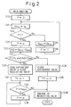
- Figure 2 is a flow chart for determining the respiratory phase in the apparatus of Figure 1.
- Figure 3 is a flow chart for controlling the degree of the opening the pressure regulating valve.
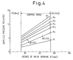
- Figure 4 illustrates experimental data of the pressure of the respiratory gas within the respiratory gas conduit relative to the degree of the opening of the pressure regulating valve for various values of the flow resistance parameter.
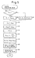
- Figure 5 is another flow chart for controlling the degree of the opening the pressure regulating valve, in which the predicted flow resistance parameter is calculated by a second order extrapolation.
- Figure 6 is another flow chart for determining the respiratory phase.
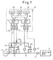
- Figure 7 is a schematic of an apparatus for ventilating the lungs of a patient according to another embodiment of the invention in which an additional expiratory valve is provided in the respiratory gas conduit.
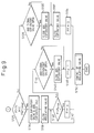
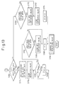
- Figures 8 and 9 are parts of a flow chart for determining the respiratory phase in the apparatus of Figure 7.
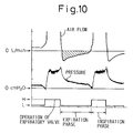
- Figure 10 illustrates the variation of the pressure and the flow rate of the respiratory gas during one respiratory cycle assisted by the apparatus of Figure 1.
- Figure 11 illustrates the variation of the pressure and the flow rate of the respiratory gas during one respiratory cycle assisted by the apparatus of Figure 7.
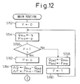
- Figures 12 and 13 are parts of another flow chart for determining the respiratory phase in the apparatus of Figure 7.
- Figure 14 is a schematic of an apparatus for ventilating the lungs of a patient according to another embodiment of the invention in which the pressure regulating valve exhausts a portion of the respiratory gas to regulate the pressure.
- the device comprises a fan 10 as a respiratory gas source to supply respiratory gas, in this embodiment air, a breathing mask 14 to be put on the face of a patient, and an respiratory gas conduit 12 provided between the fan 10 and the breathing mask 14.
- the respiratory gas source may be a blower or a pressurized tank which contains appropriate gas, such as air or oxygen.
- the respiratory gas conduit 12 may be a hose, pipe or tube.
- the device further comprises a pressure regulating valve 16 such as a motor operated butterfly valve provided in the respiratory gas conduit 12 to control the pressure within the respiratory gas conduit 12.
- the pressure regulating valve 16 uses a driving motor such as a stepping motor 16a which is electrically connected to a control unit 26 of the device as described hereinafter.
- a main expiratory valve 22 such as a piston operated shut-off valve is provided in the conduit 12 downstream of the pressure regulating valve 16.
- the main expiratory valve 22 has a piston 22a for operating the main expiratory valve 22 between the open and the closed positions.
- the piston 22a is connected to the conduit 12 upstream of the pressure regulating valve 16 through a branch conduit 25. The pressure within the conduit 12 is effectively reduced when the main expiratory valve 22 is open.
- a solenoid operated shut-off valve 24 is provided in the branch conduit 25 between the conduit 12 and the piston 22a.
- the solenoid operated shut-off valve 24 has a solenoid 24a which is electrically connected to the control unit 26.
- the solenoid operated valve 24 can operatively move between the open and the closed positions.
- the solenoid 24a When the solenoid 24a is energized, the solenoid operated shut-off valve 24 moves to the open position where the pressure within the conduit 12 upstream of the pressure regulating valve 16 is applied to the piston 22a to open the main expiratory valve 22.
- the solenoid 24a When the solenoid 24a is deenergized, the solenoid operated shut-off valve 24 moves to the closed position where the piston 22a is separated from the conduit 12 to close the main expiratory valve 22.
- a flow meter 18 such as a hot wire type flow meter or a vane type flow meter is provided in the conduit downstream of the pressure regulating valve 16.
- the flow meter 18 is also electrically connected to the control unit 26.
- the flow meter detects the flow rate of the respiratory gas within the conduit 12 and generates an electrical signal, proportional to the detected flow rate, to the control unit 26.
- a pressure sensor 20 such as a semiconductor type pressure sensor is provided in the conduit adjacent to the breathing mask 14.
- the pressure sensor 20 is electrically connected to the control unit 26 and generates an electrical signal, proportional to the detected pressure of the respiratory gas adjacent to the breathing mask 14, to the control unit 26.
- an expiratory port 21 is provided between the pressure sensor 20 and the breathing mask 14 for providing a continuous leak path in the flow system.
- the expiratory port 21 may be a Whisper Swivel (registered trade mark) which is a product of RESPIRONICS INC, 1001 Murry Ridge Drive, Murrysville, PA.
- the control unit 26 comprises a random access memory (RAM) 28, a read only memory (ROM) 30, a central processing unit (CPU) 32, an output port 34, and an input port 36 which are connected to each other by a bidirectional bus 38.
- the solenoid 24a is connected to the output port 34 through a solenoid driver 40.
- the stepping motor 16a is connected to the output port 34 through a motor driver 42.
- the flow meter 18 and the pressure sensor 20 are connected to the input port 36 through A/D converters 44 and 46.
- Figure 2 illustrates a routine for determining whether the respiration of the patient is in the expiration phase or in the inspiration phase.
- Figure 3 illustrates a routine for controlling the degree of the opening of the pressure regulating valve 16.
- step S16 the present flow rate Q Pre is input into Q Old as the old value of the flow rate.
- step S18 one is input into the flag F.
- step S12 the flow rate is read into Q pre again.
- step S20 the pressure of the respiratory gas adjacent to the respiratory gas mask 14 is detected by the pressure sensor 20, and read into P as the present value of the pressure.
- step S22 the differential value of the flow rate ⁇ Q is calculated by subtracting the old value the flow rate Q Old from the present value Q pre .
- step S24 it is determined whether the respiration is in the inspiration phase or in the expiration phase.
- the present value of the pressure P is compared with a target pressure P t , which is described hereinafter, and the differential flow rate ⁇ Q is compared with a predetermined reference value Q Ref .
- the target pressure P t is a value to which the pressure regulating valve 16 regulates the pressure of the respiratory gas within the conduit 12 adjacent to the breathing mask 14.
- PEEP positive end-expiratory pressure
- P > P t means that the respiratory gas is supplied while the patient does not want to inspire.
- the differential value of the flow rate ⁇ Q is equal to or higher than the predetermined reference value Q Ref , that is ⁇ Q ⁇ Q Ref , it can be determined that the patient is still inspiring.
- Q Ref the predetermined reference value
- P ⁇ P t means that a volume of the respiratory gas equal to the volume required by the patient is supplied, or that insufficient respiratory gas is supplied. Therefore, in this case, it can be determined that the respiration is in the inspiration phase.
- step S24 if P > P t and ⁇ Q ⁇ Q Ref , it is determined that the respiration is in the expiration phase and the routine goes-to step S30. If not, it is determined that the respiration is in the inspiration phase and the routine goes to step S26.
- step S26 the main expiratory valve 22 is closed to supply the respiratory gas to the patient efficiently.
- step S28 zero is input into flag FF to indicate the inspiration phase. Then, the routine goes to step S38 to jump to a subroutine for controlling the pressure regulating valve 16 which is shown in Figure 3.
- step S30 the main expiratory valve 22 is opened to reduce the pressure within the conduit 12 effectively. That is, the solenoid 24a of the solenoid operated shut-off valve 24 is energized by the solenoid driver 40 which results in the fluid communication between the conduit 12 upstream of the pressure regulating valve 16 and the piston 22a of the main expiratory valve 22. Thus, the main expiratory valve 22 opens to reduce the pressure within the conduit 12 rapidly and effectively.
- step S30 the pressure regulating valve 16 is completely closed to separate the respiratory gas mask 14 from the fan 10.
- the expiratory gas from the patient is exhausted through the main expiratory valve 22.
- step S32 one is input into the flag FF to indicate the expiration phase.
- step S34 it is determined whether the pressure P is higher than PEEP. If so, the routine goes to step S36 in which the present pressure within the conduit 12 is read agin, and returns to step S34. If the pressure is lower than or equal to PEEP, the routine goes to step S38.
- the device In order to assist in ventilating the lungs of a patient, in particular, in case of a patient who has sleep apnea syndrome, the device must keep the minimum pressure equal to or higher than PEEP (the minimum pressure can be higher than PEEP by a pressure, for example 0.5-1.5 cmH2O).
- the controller 26 monitors the pressure within the conduit 12 continuously in steps S34 and S36. When the pressure is reduced to a pressure level equal to or lower than PEEP, the routine goes to step S38 to jump to the subroutine for controlling the pressure regulating valve 16.
- the above mentioned routine for determining the respiration phase is executed at a time interval, preferably, within the time range of 20-50 msec and, most preferably, of 30 msec.
- step S40 in case of the inspiration phase, the routine goes to step S42.
- step S42 the target pressure P t is calculated by the above-mentioned equation (1).
- step S44 a predetermined constant target pressure P Const , which may preferably correspond to PEEP, is input into P t .
- a parameter ⁇ Pre is input into a parameter ⁇ Old .
- step S48 the present value of the parameter ⁇ Pre is calculated.
- step S50 a predicted value of the parameter ⁇ P is calculated by the first order extrapolation based on the preceding value of the parameter and the present value of the parameter as shown by the following equation.
- ⁇ P 2 ⁇ Pre - ⁇ Old
- the predicted parameter ⁇ P represents the flow resistance or flow impedance of the flow system downstream of the pressure sensor 20 including the airway, the resilience of the lungs of the patient and etc. to which value the parameter ⁇ may vary after the next time interval.
- the predicted parameter ⁇ P is calculated by the first order extrapolation.
- step S60 the routine goes to step S60 in which the degree of the opening of the pressure regulating valve 16 is determined by using the predicted parameter ⁇ P such that the pressure within the conduit 12 at the next time interval, for example after 30 msec, is suitable for the respiration, which is predicted by the parameter ⁇ P as follows.
- Figure 4 illustrates the pressure P within the conduit 12 relative to the degree ⁇ of the opening of a pressure regulating valve, which was experimentally obtained by varying the value of the parameter ⁇ .
- the experiment was carried out by a experimental apparatus which comprises a air source, an air conduit, a pressure regulating valve on the air conduit, a sensor for detecting the degree of the opening of the pressure regulating valve, a flow meter on the air conduit downstream of the pressure regulating valve, a pressure sensor on the air conduit downstream of the flow meter, and a variable orifice on the air conduit downstream of the pressure sensor.
- the parameter ⁇ represents the flow resistance or flow impedance of a flow system downstream of the pressure sensor, and does not depend on the constitution of the flow system but only on the flow resistance. Therefore it can be determined by only the flow resistance.
- the experimental data can be used for determine the degree of the opening of the pressure regulating valve of an actual device for assisting in ventilating the lungs of a patient, if the pressure regulating valve of the actual device is the same as the experimental apparatus.
- the experimental data is stored in the ROM 30 of the controller 26 in the form of linear equations.
- the experimental data can be stored in the ROM 30 in the form of a data table.
- step S60 the routine goes to step S62 in which the motor operated valve 16 is controlled its degree of opening.
- the degree of the opening of the pressure regulating valve is controlled so that the pressure within the air conduit adjacent to the breathing mask becomes the target pressure based on prediction and not on feed-back control.
- Figure 5 illustrates a routine for controlling the motor operated butterfly valve 16 to regulate the pressure according to the second embodiment of the invention.
- This routine is the same as one in Figure 3 except for step S78.
- the predicted parameter ⁇ P is calculated by the first order extrapolation.
- the predicted parameter ⁇ P can be obtained by the second order extrapolation as shown in step S78.
- the respiration phase is determined by the present pressure adjacent to the respiratory gas mask 14, the differential value of the flow rate of the respiratory gas, and the differential value of the pressure while it is determined by the present pressure, and the differential value of the flow rate, in the embodiment described with reference to Figure 2.
- step S84 the routine for determining the phase of the respiration shown in Figure 6 goes to step S84 in which zero is input to flag F.
- step S86 the present value of the flow rate and the pressure are read into Q pre and P pre by the flow meter 18 and the pressure sensor 20.
- step S88 the present value of the flow rate Q Pre is input into Q Old , and the present value of the pressure P Pre is input into P Old .
- step S90 one is input into the flag F. Then, the routine goes to step S86.
- step S86 the flow rate and the pressure are read into Q pre and P pre again.
- step S92 the present value of the pressure P pre is input into P.
- step S94 the differential value of the flow rate ⁇ Q and the pressure ⁇ P are calculated by subtracting the old value of the flow rate and of the pressure Q Old and P Old from the present value Q pre and P pre respectively.
- step S96 the respiration phase is determined.
- the present pressure P is compared with the target pressure P t
- the differential flow rate ⁇ Q is compared with a predetermined reference flow rate Q Ref as in the preceding embodiments.
- the differential pressure ⁇ P is compared with a reference differential pressure ⁇ P Ref .
- the other steps are the same as those of the flow chart shown in Figure 2.
- the device for assisting in ventilating the lungs of a patient further comprises an additional expiratory valve, such as a piston operated shut-off valve 48 on the conduit 12 downstream of the flow meter 18 and upstream of the pressure sensor 20.
- the piston operated shut-off valve 48 has a piston 48a for operating the shut-off valve 48 between open and closed position.
- the piston 48a is connected to the conduit 12 upstream of the pressure regulating valve 16 through a second branch conduit 50 and a first branch conduit 25. The pressure within the conduit 12 is more effectively reduced when the piston operated shut-off valves 22 and 48 are open compared with the embodiment of Figure 1.
- a solenoid operated shut-off valve 52 is provided in the second branch conduit 50 between the first branch conduit 25 and the piston 48a.
- the solenoid operated shut-off valve 52 has a solenoid 52a which is electrically connected to the control unit 26.
- the solenoid operated valve 52 can operatively move between open and closed positions.
- the solenoid 52a When the solenoid 52a is energized, the solenoid operated shut-off valve 52 moves to the open position where the pressure within the conduit 12 upstream of the pressure regulating valve 16 is applied to the piston 52a to open the piston operated shut-off valve 48.
- the solenoid 52a When the solenoid 52a is deenergized, the solenoid operated shut-off valve 52 moves to the closed position where the piston 52a is separated from the conduit 12.
- the control unit 26 comprises a random access memory (RAM) 28, a read only memory (ROM) 30, a central processing unit (CPU) 32, an output port 34, and an input port 36 which are connected to each other by a bidirectional bus 38.
- the solenoids 24a and 52a are connected to the output port 34 through solenoid drivers 40 and 54.
- Figures 8 and 9 illustrate a routine for determining the respiration phase and operating the main expiratory valve 22 and the additional expiratory valve 48. Steps S112 through S126 are the same as the steps S10 through S24 shown in Figure 2.
- step S126 it is determined whether the respiration is in the expiration phase or in the inspiration phase by the present pressure adjacent to the respiratory gas mask and the differential flow rate of the respiratory gas as in the embodiment of Figure 1.
- step S128 When the respiration is in the inspiration phase, the routine goes to step S128 in which it is determined whether the additional expiratory valve 48 is open. If not, the routine goes to step S132 to close the main expiratory valve 22. If the additional expiratory valve 48 is open, it is closed in step S130. That is, the solenoid 52a of the solenoid operated shut-off valve 52 is deenergized which results in separating the piston 48a of the additional expiratory valve 48 from the conduit 12. Thus, the additional expiratory valve 48 is closed.
- step S132 the main expiratory valve 22 is closed to supply the respiratory gas to the patient efficiently
- step S134 zero is input into flag FF to indicate the inspiration phase. Then, the routine goes to the routine for controlling the pressure regulating valve 16 in step S150.
- the routine for controlling the pressure regulating valve 16 was already described.
- step S126 if the respiration is in the expiration phase, the routine goes to step S136 in which the main expiratory valve 22 and the additional expiratory valve 48 are opened to reduce the pressure within the conduit 12 effectively. That is, the solenoids 24a and 52a of the solenoid operated shut-off valves 24 and 52 are energized by the solenoid drivers 40 and 54 which results in fluid communication between the conduit 12 upstream of the pressure regulating valve 16 and the pistons 22a and 52a of the main expiratory valve 22 and the additional expiratory valve 52. Thus, the main expiratory valve 22 and the additional expiratory valve 52 are opened to reduce the pressure within the conduit 12 rapidly and effectively.
- step S138 the pressure regulating valve 16 is completely closed to separate the respiratory gas mask 14 from the fan 10.
- the expiratory gas from the patient is exhausted through the main expiratory valve 22 and the additional expiratory valve 48.
- providing the additional expiratory valve 48 on the conduit 12 adjacent to the respiratory gas mask 14 allows the expiratory gas from the patient to be exhaust directly, which results in substantially no reverse flow of the expiratory gas through the conduit 12. Therefore, there is substantially no expiratory gas remaining within the conduit 12, which is particularly advantageous in case of low PEEP.
- a lower PEEP makes the pressure regulating valve close during the longer time, since the step 106 keeps the routine waiting until the pressure is reduced to PEEP, during which the expiratory gas from the patient reversely flows to the main expiratory valve 22. Therefore, the conduit 12 is filled with the expiratory gas which includes carbon dioxide.
- the pressure regulating valve is controlled to regulate the pressure at PEEP in step S32 or S110 which allows the respiratory gas to flow to downstream.
- the lower PEEP allows the lower flow rate. Therefore, the expiratory gas within the conduit 12 cannot be exhausted sufficiently through the expiratory port 21.
- the additional expiratory valve can reduce the reverse flow of the expiratory gas to the main expiratory valve 22.
- step S140 it is determined whether the pressure P is higher than PEEP. If so, the routine goes to step S142 in which the present pressure within the conduit 12 is read agin, and returns to step S140. If the pressure is lower than or equal to PEEP, the routine goes to step S144.
- step S144 it is determined whether the additional expiratory valve 48 is open. If not, the routine goes to step S148. If the additional expiratory valve 48 is open, it is closed in step S146. That is, the solenoid 52a of the solenoid operated shut-off valve 52 is deenergized which results in separating the piston 48a of the additional expiratory valve 48 from the conduit 12. Thus, the additional expiratory valve 48 is closed.
- step S148 one is input into flag FF to indicate the expiration phase. Then, the routine goes to the routine for controlling the pressure regulating valve 16 in step S150.
- the routine for controlling the pressure regulating valve 16 was already described.
- Figures 10 and 11 illustrate the variations in the pressure and the flow rate of the respiratory gas during one cycle of a respiration assisted by the inventive device with only the main expiratory valve ( Figure 10) and both the main and additional expiratory valves (Figure 11).
- the high signal (H) indicates that the main expiratory valve and the additional expiratory valve open
- the low signal (L) indicates that the main expiratory valve and the additional expiratory valve close.
- the device according to the embodiment of Figure 7 can be also operated to determine whether the respiration is in the expiration phase by using the present pressure and the differential pressure of the respiratory gas adjacent to the breathing mask, and the differential flow rate of the respiratory gas as shown in a flow chart of Figures 12 and 13.
- the pressure regulating valve that is, the pressure regulating valve 16 has inlet and outlet ports which are connected to the discharge port of the fan 10 and the inlet port, of the breathing mask 14, respectively. Therefore, substantially all the air flow from the fan passes through the pressure regulating valve 16.
- the motor operated valve 16 can regulate the pressure within the conduit 12 by exhausting the respiratory gas as shown in Figure 14.
- the pressure regulating valve is a pressure regulating valve 17 with a driving motor 17a which is electrically connected to the output port 34 of the controller 26 through the motor driver 42.
- the pressure regulating valve 17 has an inlet port connected to the conduit 12 and an outlet port opening to the environment.
- the pressure regulating valve 17 regulates the pressure within the conduit 12 downstream thereof by exhausting a portion of the respiratory gas from the fan 10.
Landscapes
- Health & Medical Sciences (AREA)
- Emergency Medicine (AREA)
- Pulmonology (AREA)
- Engineering & Computer Science (AREA)
- Anesthesiology (AREA)
- Biomedical Technology (AREA)
- Heart & Thoracic Surgery (AREA)
- Hematology (AREA)
- Life Sciences & Earth Sciences (AREA)
- Animal Behavior & Ethology (AREA)
- General Health & Medical Sciences (AREA)
- Public Health (AREA)
- Veterinary Medicine (AREA)
- Measurement Of The Respiration, Hearing Ability, Form, And Blood Characteristics Of Living Organisms (AREA)
- Respiratory Apparatuses And Protective Means (AREA)
Applications Claiming Priority (8)
| Application Number | Priority Date | Filing Date | Title |
|---|---|---|---|
| JP154761/94 | 1994-07-06 | ||
| JP15475994A JP3160152B2 (ja) | 1994-07-06 | 1994-07-06 | 呼吸補助装置 |
| JP15476094A JPH0819613A (ja) | 1994-07-06 | 1994-07-06 | 気道陽圧式の呼吸補助装置 |
| JP15476194A JP3160153B2 (ja) | 1994-07-06 | 1994-07-06 | 呼吸同調型の呼吸補助装置 |
| JP154759/94 | 1994-07-06 | ||
| JP154760/94 | 1994-07-06 | ||
| JP05249095A JP3247273B2 (ja) | 1995-03-13 | 1995-03-13 | 呼吸同調型呼吸補助装置 |
| JP52490/95 | 1995-03-13 |
Publications (2)
| Publication Number | Publication Date |
|---|---|
| EP0691134A2 true EP0691134A2 (de) | 1996-01-10 |
| EP0691134A3 EP0691134A3 (de) | 1996-03-13 |
Family
ID=27462780
Family Applications (1)
| Application Number | Title | Priority Date | Filing Date |
|---|---|---|---|
| EP95110536A Ceased EP0691134A3 (de) | 1994-07-06 | 1995-07-06 | Vorrichtung zur Unterstützung der Beatmung eines Patienten |
Country Status (3)
| Country | Link |
|---|---|
| US (1) | US5572993A (de) |
| EP (1) | EP0691134A3 (de) |
| AU (1) | AU683753B2 (de) |
Cited By (8)
| Publication number | Priority date | Publication date | Assignee | Title |
|---|---|---|---|---|
| FR2755017A1 (fr) * | 1996-10-30 | 1998-04-30 | Taema | Dispositif d'assistance respiratoire |
| EP0903159A1 (de) * | 1997-09-11 | 1999-03-24 | Siemens-Elema AB | Beatmungsgerät |
| WO2001042745A1 (en) * | 1999-12-06 | 2001-06-14 | Trojan Technologies Inc. | An on-line device for predicting at least one fluid flow parameter in a process |
| US6533730B2 (en) | 1999-12-17 | 2003-03-18 | Siemens Aktiengesellschaft | Method for assessing pulmonary stress and breathing apparatus employing the method |
| EP1136094B1 (de) * | 2000-03-24 | 2006-04-26 | Weinmann Geräte für Medizin GmbH & Co. KG | Beatmungsgerät mit einer Überwachungsvorrichtung |
| EP2106819A1 (de) * | 2008-03-31 | 2009-10-07 | Linde AG | Druckstützbelüftung mit passivem PEEP-Ventil |
| CN105980014A (zh) * | 2013-03-15 | 2016-09-28 | 呼吸科技公司 | 双压力传感器患者通气设备 |
| WO2019129676A1 (en) * | 2017-12-28 | 2019-07-04 | Koninklijke Philips N.V. | System and method for providing high-flow nasal therapy |
Families Citing this family (32)
| Publication number | Priority date | Publication date | Assignee | Title |
|---|---|---|---|---|
| IL114022A0 (en) * | 1995-06-06 | 1995-10-31 | Pastel Manag Ltd | A respiration device |
| AUPO418696A0 (en) | 1996-12-12 | 1997-01-16 | Resmed Limited | A substance delivery apparatus |
| US5884622A (en) * | 1996-12-20 | 1999-03-23 | University Of Manitoba | Automatic determination of passive elastic and resistive properties of the respiratory system during assisted mechanical ventilation |
| US6067984A (en) * | 1997-10-14 | 2000-05-30 | Piper; Samuel David | Pulmonary modulator apparatus |
| SE9802121D0 (sv) * | 1998-06-15 | 1998-06-15 | Siemens Elema Ab | Förfarande för styrning av en exspirationsventil i en ventilator |
| US6631716B1 (en) * | 1998-07-17 | 2003-10-14 | The Board Of Trustees Of The Leland Stanford Junior University | Dynamic respiratory control |
| SE9802827D0 (sv) * | 1998-08-25 | 1998-08-25 | Siemens Elema Ab | Ventilator |
| US7073501B2 (en) * | 1999-02-04 | 2006-07-11 | Univerity Technologies International Inc. | Ventilatory stabilization technology |
| US6752150B1 (en) * | 1999-02-04 | 2004-06-22 | John E. Remmers | Ventilatory stabilization technology |
| WO2000078380A1 (en) * | 1999-06-23 | 2000-12-28 | Graham Cameron Grant | Respiration assistor |
| US6595212B1 (en) * | 2000-04-17 | 2003-07-22 | Richard J. Arnott | Method and apparatus for maintaining airway patency |
| WO2001083014A2 (en) * | 2000-04-26 | 2001-11-08 | The University Of Manitoba | Method and apparatus for determining respiratory system resistance during assisted ventilation |
| US6626175B2 (en) * | 2000-10-06 | 2003-09-30 | Respironics, Inc. | Medical ventilator triggering and cycling method and mechanism |
| US6644311B1 (en) * | 2001-02-21 | 2003-11-11 | Respironics, Inc. | Monitoring fluid flow in a pressure support system |
| US7244235B2 (en) * | 2002-10-30 | 2007-07-17 | Mallinckrodt, Inc. | Split-night sleep diagnostic system |
| US20090096936A1 (en) * | 2006-04-24 | 2009-04-16 | Panasonic Corporation | Receiving device, electronic device using the same, and receiving method |
| CN101765401B (zh) * | 2007-07-26 | 2013-09-25 | 优特埃合伙有限公司 | 用于调整患者呼吸的瞬时介入 |
| AU2008203812B2 (en) * | 2007-08-17 | 2014-10-02 | ResMed Pty Ltd | Methods and Apparatus for Pressure Therapy in the Treatment of Sleep Disordered Breathing |
| US8251876B2 (en) | 2008-04-22 | 2012-08-28 | Hill-Rom Services, Inc. | Breathing exercise apparatus |
| US8783251B2 (en) * | 2010-02-12 | 2014-07-22 | Piper Medical, Inc | Enhanced manually actuated pressure controlled modulator technology |
| US8776792B2 (en) | 2011-04-29 | 2014-07-15 | Covidien Lp | Methods and systems for volume-targeted minimum pressure-control ventilation |
| US9180271B2 (en) | 2012-03-05 | 2015-11-10 | Hill-Rom Services Pte. Ltd. | Respiratory therapy device having standard and oscillatory PEP with nebulizer |
| US9993604B2 (en) | 2012-04-27 | 2018-06-12 | Covidien Lp | Methods and systems for an optimized proportional assist ventilation |
| US9144658B2 (en) * | 2012-04-30 | 2015-09-29 | Covidien Lp | Minimizing imposed expiratory resistance of mechanical ventilator by optimizing exhalation valve control |
| US9375542B2 (en) | 2012-11-08 | 2016-06-28 | Covidien Lp | Systems and methods for monitoring, managing, and/or preventing fatigue during ventilation |
| US9358355B2 (en) | 2013-03-11 | 2016-06-07 | Covidien Lp | Methods and systems for managing a patient move |
| CN111603643B (zh) | 2015-04-02 | 2023-05-23 | 希尔-罗姆服务私人有限公司 | 呼吸装置的压力控制 |
| AU2017267246B2 (en) * | 2016-05-17 | 2022-04-07 | Fisher & Paykel Healthcare Limited | Flow path sensing for flow therapy apparatus |
| EP3525857B1 (de) | 2017-11-14 | 2020-01-29 | Covidien LP | System für antriebsdruck-spontanatmung |
| US11517691B2 (en) | 2018-09-07 | 2022-12-06 | Covidien Lp | Methods and systems for high pressure controlled ventilation |
| US11375950B2 (en) * | 2019-09-24 | 2022-07-05 | Calibre Biometrics Inc. | Systems and methods for measuring respiratory biometrics |
| CN114469060B (zh) * | 2021-12-31 | 2025-02-25 | 天津怡和嘉业医疗科技有限公司 | 呼吸相确定方法、装置 |
Citations (7)
| Publication number | Priority date | Publication date | Assignee | Title |
|---|---|---|---|---|
| JPS5316238A (en) | 1976-07-26 | 1978-02-15 | Tomihito Shiyamoto | Hydraulic transmission vehicle |
| US4655213A (en) | 1983-10-06 | 1987-04-07 | New York University | Method and apparatus for the treatment of obstructive sleep apnea |
| JPH03222963A (ja) | 1989-09-22 | 1991-10-01 | Respironics Inc | 治療装置 |
| EP0452001A2 (de) | 1990-03-30 | 1991-10-16 | University Of Manitoba | Beatmungsgerät |
| JPH04231067A (ja) | 1990-05-11 | 1992-08-19 | Puritan Bennett Corp | 呼吸補助換気の流量始動装置 |
| JPH04263876A (ja) | 1991-02-18 | 1992-09-18 | Toray Ind Inc | グリップエンド、それを装着したスポーツ用具、自転車および工具 |
| JPH0538435A (ja) | 1991-08-08 | 1993-02-19 | Matsushita Electric Ind Co Ltd | 触媒組成物 |
Family Cites Families (13)
| Publication number | Priority date | Publication date | Assignee | Title |
|---|---|---|---|---|
| US3910270A (en) * | 1972-09-11 | 1975-10-07 | Bio Med Devices Inc | Portable volume cycle respirator |
| US4031885A (en) * | 1975-10-15 | 1977-06-28 | Puritan-Bennett Corporation | Method and apparatus for determining patient lung pressure, compliance and resistance |
| DE3021326A1 (de) * | 1980-06-06 | 1981-12-17 | Drägerwerk AG, 2400 Lübeck | Einrichtung zur messung von mindestens zwei pneumatischen lungenparametern und messverfahren hierzu |
| US4351344A (en) * | 1980-11-13 | 1982-09-28 | Bio-Med Devices, Inc. | Method and apparatus for monitoring lung compliance |
| FR2554706B1 (fr) * | 1983-11-15 | 1987-07-31 | Centre Nat Rech Scient | Dispositif commande d'occlusion rapide |
| GB8511170D0 (en) * | 1985-05-02 | 1985-06-12 | Pneupac Ltd | Resuscitator/ventilator |
| DE3817985A1 (de) * | 1988-05-27 | 1989-12-07 | Salvia Werk Gmbh | Geraet zur unterstuetzung der spontanen atmung eines patienten |
| US5134995A (en) * | 1989-05-19 | 1992-08-04 | Puritan-Bennett Corporation | Inspiratory airway pressure system with admittance determining apparatus and method |
| US5239995A (en) * | 1989-09-22 | 1993-08-31 | Respironics, Inc. | Sleep apnea treatment apparatus |
| JP2714288B2 (ja) * | 1991-10-18 | 1998-02-16 | ユニヴァーシティー オブ マニトーバ | 比例支援式人工呼吸方法および装置 |
| US5335654A (en) * | 1992-05-07 | 1994-08-09 | New York University | Method and apparatus for continuous adjustment of positive airway pressure for treating obstructive sleep apnea |
| US5293875A (en) * | 1992-06-16 | 1994-03-15 | Natus Medical Incorporated | In-vivo measurement of end-tidal carbon monoxide concentration apparatus and methods |
| WO1994006499A1 (fr) * | 1992-09-18 | 1994-03-31 | Pierre Medical S.A. | Dispositif d'aide a la respiration |
-
1995
- 1995-07-05 AU AU24845/95A patent/AU683753B2/en not_active Expired
- 1995-07-06 EP EP95110536A patent/EP0691134A3/de not_active Ceased
- 1995-07-06 US US08/498,751 patent/US5572993A/en not_active Expired - Lifetime
Patent Citations (7)
| Publication number | Priority date | Publication date | Assignee | Title |
|---|---|---|---|---|
| JPS5316238A (en) | 1976-07-26 | 1978-02-15 | Tomihito Shiyamoto | Hydraulic transmission vehicle |
| US4655213A (en) | 1983-10-06 | 1987-04-07 | New York University | Method and apparatus for the treatment of obstructive sleep apnea |
| JPH03222963A (ja) | 1989-09-22 | 1991-10-01 | Respironics Inc | 治療装置 |
| EP0452001A2 (de) | 1990-03-30 | 1991-10-16 | University Of Manitoba | Beatmungsgerät |
| JPH04231067A (ja) | 1990-05-11 | 1992-08-19 | Puritan Bennett Corp | 呼吸補助換気の流量始動装置 |
| JPH04263876A (ja) | 1991-02-18 | 1992-09-18 | Toray Ind Inc | グリップエンド、それを装着したスポーツ用具、自転車および工具 |
| JPH0538435A (ja) | 1991-08-08 | 1993-02-19 | Matsushita Electric Ind Co Ltd | 触媒組成物 |
Cited By (14)
| Publication number | Priority date | Publication date | Assignee | Title |
|---|---|---|---|---|
| FR2755017A1 (fr) * | 1996-10-30 | 1998-04-30 | Taema | Dispositif d'assistance respiratoire |
| EP0839545A1 (de) * | 1996-10-30 | 1998-05-06 | Taema | Vorrichtung zur Unterstützung der Atmung |
| US6173711B1 (en) | 1996-10-30 | 2001-01-16 | Taema | Respiratory assistance device |
| EP0903159A1 (de) * | 1997-09-11 | 1999-03-24 | Siemens-Elema AB | Beatmungsgerät |
| US6095139A (en) * | 1997-09-11 | 2000-08-01 | Siemens Elema Ab | Ventilator suitable for miniaturization |
| WO2001042745A1 (en) * | 1999-12-06 | 2001-06-14 | Trojan Technologies Inc. | An on-line device for predicting at least one fluid flow parameter in a process |
| US6533730B2 (en) | 1999-12-17 | 2003-03-18 | Siemens Aktiengesellschaft | Method for assessing pulmonary stress and breathing apparatus employing the method |
| EP1136094B1 (de) * | 2000-03-24 | 2006-04-26 | Weinmann Geräte für Medizin GmbH & Co. KG | Beatmungsgerät mit einer Überwachungsvorrichtung |
| EP2106819A1 (de) * | 2008-03-31 | 2009-10-07 | Linde AG | Druckstützbelüftung mit passivem PEEP-Ventil |
| CN105980014A (zh) * | 2013-03-15 | 2016-09-28 | 呼吸科技公司 | 双压力传感器患者通气设备 |
| CN105980014B (zh) * | 2013-03-15 | 2019-07-26 | 呼吸科技公司 | 双压力传感器患者通气设备 |
| WO2019129676A1 (en) * | 2017-12-28 | 2019-07-04 | Koninklijke Philips N.V. | System and method for providing high-flow nasal therapy |
| CN111556770A (zh) * | 2017-12-28 | 2020-08-18 | 皇家飞利浦有限公司 | 用于提供高流量的鼻治疗的系统和方法 |
| CN111556770B (zh) * | 2017-12-28 | 2023-09-05 | 皇家飞利浦有限公司 | 用于提供高流量的鼻治疗的系统和方法 |
Also Published As
| Publication number | Publication date |
|---|---|
| US5572993A (en) | 1996-11-12 |
| AU2484595A (en) | 1996-01-18 |
| AU683753B2 (en) | 1997-11-20 |
| EP0691134A3 (de) | 1996-03-13 |
Similar Documents
| Publication | Publication Date | Title |
|---|---|---|
| US5572993A (en) | Apparatus for assisting in ventilating the lungs of a patient | |
| US5918597A (en) | Peep control in a piston ventilator | |
| US6216690B1 (en) | Method and apparatus for rapid control of set inspired gas concentration in anesthesia delivery systems | |
| US5094235A (en) | Anesthesia ventilating apparatus having a breathing circuit and control loops for anesthetic gas components | |
| US6880556B2 (en) | Apparatus for supplying a therapeutic oxygen gas | |
| US6533730B2 (en) | Method for assessing pulmonary stress and breathing apparatus employing the method | |
| US5813399A (en) | System and method for closed loop airway pressure control during the inspiratory cycle of a breath in a patient ventilator using the exhalation valve as a microcomputer-controlled relief valve | |
| US7106955B2 (en) | Humidity controller | |
| EP1207929B1 (de) | Vorrichtung zur Feuchtigkeitskontrolle | |
| EP1326671B1 (de) | Beatmungsgerat mit doppelgaszufuhr | |
| US6571796B2 (en) | Tracheal pressure ventilation respiratory system | |
| EP0835672B1 (de) | Verabreichungssystem für Narkosemittel | |
| EP0560490B1 (de) | System zur Steuerung eines periodisch arbeitenden Beatmungsgerätes | |
| US9186477B2 (en) | Humidity controller | |
| US6412483B1 (en) | Oxygen blending in a piston ventilator | |
| US7086098B2 (en) | Mechanical breathing aid with adaptive expiration control | |
| JPH105337A (ja) | 医療用人工呼吸装置 | |
| JP2009500124A (ja) | モジュール型補充気体調整器及びそれを使用する呼吸治療装置 | |
| JPH10505765A (ja) | 圧力制御式呼吸補助装置 | |
| JPH11514909A (ja) | 送風装置を基本とする換気装置への酸素混合 | |
| US10130787B2 (en) | Humidity controller | |
| EP0615764B1 (de) | Vorrichtung und Verfahren zur Steuerung eines geschlossenen Regelkreises zum Einatmungsdruck in einem Beatmungsgerät | |
| US20050039740A1 (en) | Method and system for the controlled admixing of a gas or a gas mixture to a gas (mixture) flow | |
| JPH1052493A (ja) | 生物に空気および少なくとも1つの付加ガスを供給するための装置 | |
| KR100558088B1 (ko) | 배기특성 조정 기능을 갖는 인공호흡 장치 |
Legal Events
| Date | Code | Title | Description |
|---|---|---|---|
| PUAI | Public reference made under article 153(3) epc to a published international application that has entered the european phase |
Free format text: ORIGINAL CODE: 0009012 |
|
| AK | Designated contracting states |
Kind code of ref document: A2 Designated state(s): DE FR GB |
|
| PUAL | Search report despatched |
Free format text: ORIGINAL CODE: 0009013 |
|
| AK | Designated contracting states |
Kind code of ref document: A3 Designated state(s): DE FR GB |
|
| 17P | Request for examination filed |
Effective date: 19960820 |
|
| 17Q | First examination report despatched |
Effective date: 19990621 |
|
| GRAG | Despatch of communication of intention to grant |
Free format text: ORIGINAL CODE: EPIDOS AGRA |
|
| STAA | Information on the status of an ep patent application or granted ep patent |
Free format text: STATUS: THE APPLICATION HAS BEEN REFUSED |
|
| 18R | Application refused |
Effective date: 20020824 |