EP0691190A2 - Vorrichtung zur Herstellung von fotografischen Filmen - Google Patents
Vorrichtung zur Herstellung von fotografischen Filmen Download PDFInfo
- Publication number
- EP0691190A2 EP0691190A2 EP95109838A EP95109838A EP0691190A2 EP 0691190 A2 EP0691190 A2 EP 0691190A2 EP 95109838 A EP95109838 A EP 95109838A EP 95109838 A EP95109838 A EP 95109838A EP 0691190 A2 EP0691190 A2 EP 0691190A2
- Authority
- EP
- European Patent Office
- Prior art keywords
- film
- length
- cutter
- continuous film
- filmstrip
- Prior art date
- Legal status (The legal status is an assumption and is not a legal conclusion. Google has not performed a legal analysis and makes no representation as to the accuracy of the status listed.)
- Granted
Links
- 238000004519 manufacturing process Methods 0.000 title claims abstract description 18
- 230000002093 peripheral effect Effects 0.000 claims abstract description 12
- 238000004080 punching Methods 0.000 claims description 23
- 238000005520 cutting process Methods 0.000 claims description 10
- 230000000694 effects Effects 0.000 claims description 4
- 239000000839 emulsion Substances 0.000 claims description 4
- 238000010586 diagram Methods 0.000 description 14
- 230000002950 deficient Effects 0.000 description 3
- 238000001514 detection method Methods 0.000 description 2
- 238000000034 method Methods 0.000 description 2
- 238000012544 monitoring process Methods 0.000 description 2
- 230000003213 activating effect Effects 0.000 description 1
- 230000012447 hatching Effects 0.000 description 1
- 238000012986 modification Methods 0.000 description 1
- 230000004048 modification Effects 0.000 description 1
- 239000011347 resin Substances 0.000 description 1
- 229920005989 resin Polymers 0.000 description 1
Images






Classifications
-
- B—PERFORMING OPERATIONS; TRANSPORTING
- B26—HAND CUTTING TOOLS; CUTTING; SEVERING
- B26F—PERFORATING; PUNCHING; CUTTING-OUT; STAMPING-OUT; SEVERING BY MEANS OTHER THAN CUTTING
- B26F1/00—Perforating; Punching; Cutting-out; Stamping-out; Apparatus therefor
- B26F1/0007—Perforation of photographic films
-
- B—PERFORMING OPERATIONS; TRANSPORTING
- B26—HAND CUTTING TOOLS; CUTTING; SEVERING
- B26D—CUTTING; DETAILS COMMON TO MACHINES FOR PERFORATING, PUNCHING, CUTTING-OUT, STAMPING-OUT OR SEVERING
- B26D9/00—Cutting apparatus combined with punching or perforating apparatus or with dissimilar cutting apparatus
-
- B—PERFORMING OPERATIONS; TRANSPORTING
- B26—HAND CUTTING TOOLS; CUTTING; SEVERING
- B26F—PERFORATING; PUNCHING; CUTTING-OUT; STAMPING-OUT; SEVERING BY MEANS OTHER THAN CUTTING
- B26F1/00—Perforating; Punching; Cutting-out; Stamping-out; Apparatus therefor
- B26F1/02—Perforating by punching, e.g. with relatively-reciprocating punch and bed
- B26F1/04—Perforating by punching, e.g. with relatively-reciprocating punch and bed with selectively-operable punches
-
- B—PERFORMING OPERATIONS; TRANSPORTING
- B26—HAND CUTTING TOOLS; CUTTING; SEVERING
- B26F—PERFORATING; PUNCHING; CUTTING-OUT; STAMPING-OUT; SEVERING BY MEANS OTHER THAN CUTTING
- B26F1/00—Perforating; Punching; Cutting-out; Stamping-out; Apparatus therefor
- B26F1/18—Perforating by slitting, i.e. forming cuts closed at their ends without removal of material
- B26F1/20—Perforating by slitting, i.e. forming cuts closed at their ends without removal of material with tools carried by a rotating drum or similar support
-
- B—PERFORMING OPERATIONS; TRANSPORTING
- B65—CONVEYING; PACKING; STORING; HANDLING THIN OR FILAMENTARY MATERIAL
- B65H—HANDLING THIN OR FILAMENTARY MATERIAL, e.g. SHEETS, WEBS, CABLES
- B65H20/00—Advancing webs
- B65H20/02—Advancing webs by friction roller
- B65H20/04—Advancing webs by friction roller to effect step-by-step advancement of web
-
- B—PERFORMING OPERATIONS; TRANSPORTING
- B65—CONVEYING; PACKING; STORING; HANDLING THIN OR FILAMENTARY MATERIAL
- B65H—HANDLING THIN OR FILAMENTARY MATERIAL, e.g. SHEETS, WEBS, CABLES
- B65H20/00—Advancing webs
- B65H20/12—Advancing webs by suction roller
-
- B—PERFORMING OPERATIONS; TRANSPORTING
- B65—CONVEYING; PACKING; STORING; HANDLING THIN OR FILAMENTARY MATERIAL
- B65H—HANDLING THIN OR FILAMENTARY MATERIAL, e.g. SHEETS, WEBS, CABLES
- B65H35/00—Delivering articles from cutting or line-perforating machines; Article or web delivery apparatus incorporating cutting or line-perforating devices, e.g. adhesive tape dispensers
- B65H35/0006—Article or web delivery apparatus incorporating cutting or line-perforating devices
-
- B—PERFORMING OPERATIONS; TRANSPORTING
- B65—CONVEYING; PACKING; STORING; HANDLING THIN OR FILAMENTARY MATERIAL
- B65H—HANDLING THIN OR FILAMENTARY MATERIAL, e.g. SHEETS, WEBS, CABLES
- B65H35/00—Delivering articles from cutting or line-perforating machines; Article or web delivery apparatus incorporating cutting or line-perforating devices, e.g. adhesive tape dispensers
- B65H35/0006—Article or web delivery apparatus incorporating cutting or line-perforating devices
- B65H35/006—Article or web delivery apparatus incorporating cutting or line-perforating devices with means for delivering a predetermined length of tape
-
- B—PERFORMING OPERATIONS; TRANSPORTING
- B65—CONVEYING; PACKING; STORING; HANDLING THIN OR FILAMENTARY MATERIAL
- B65H—HANDLING THIN OR FILAMENTARY MATERIAL, e.g. SHEETS, WEBS, CABLES
- B65H2301/00—Handling processes for sheets or webs
- B65H2301/40—Type of handling process
- B65H2301/44—Moving, forwarding, guiding material
- B65H2301/449—Features of movement or transforming movement of handled material
- B65H2301/4491—Features of movement or transforming movement of handled material transforming movement from continuous to intermittent or vice versa
Definitions
- the present invention relates to an apparatus for manufacturing photographic filmstrips from a long strip of photographic film, especially for manufacturing photographic filmstrips having one or two perforations and data per picture frame along one or both of lateral sides thereof by perforating, data recording and cutting the long film.
- Leader-advancing type photographic film cassette have been disclosed, e.g., in U.S.P. No. 4,846,418, in which the whole length of a filmstrip is contained within a cassette shell, and a film leader of the filmstrip can be advanced to the outside of the cassette shell by rotating a spool of the cassette.
- a camera need not have such a sprocket wheel that has conventionally been used for feeding the film leader to the take-up spool of the camera.
- the filmstrip may be advanced by rotating the take-up spool. Therefore, the filmstrip of the leader-advancing type cassette need not have a lot of successive perforations which like conventional 135-type filmstrips have for engagement with the sprocket wheel or the take-up spool.
- the filmstrip of the leader advancing type cassette has at least a perforation per picture frame.
- the perforation is intended to be detected by a photo-sensor in the camera to determine each frame exposure location and position it in an exposure aperture of the camera. Since these perforations for frame positioning are disposed in association with the frame exposure locations, the filmstrip of the leader advancing type cassette, hereinafter referred to as a new type filmstrip, has no positioning perforation in its leader and trailer where no picture frame is to be recorded.
- a section which extends over the frame exposure locations of each individual filmstrip will be referred to as a recording section.
- apparatuses for manufacturing the new type filmstrip have been suggested, one of which uses a die set having a number of punches and dies corresponding to the number of frame exposure locations to be provided in the individual filmstrips formed from the long film.
- the apparatus makes the corresponding number of perforations at a time in the recording section of each individual filmstrip.
- the number of frame exposure locations per filmstrip will be referred to as film frame number.
- a similar method has conventionally been applied to manufacturing 110-type filmstrips.
- the long film 12 is fed from a roll 10 to a first vacuum suction chamber 15 through a dancer roller 13 and a sub-feed rollers 14.
- the suction chamber 15 transiently stores an appropriate length of the long film 12 before being fed to the die set 17 through a pass roller 16.
- the die set 17 has a punch holder 19 with the same number of punches 18 as the film frame number, and a dies plate 21 with the corresponding number of dies 20.
- the punches and dies 18 and 20 are arranged at the same intervals as the frame exposure locations.
- An air cylinder 22 is driven to move the punch holder 19 down to the dies plate 21 while the long film 12 stops on the dies plate 21, making the same number of perforations as the film frame number at a time.
- first vacuum suction drum 24 Downstream of the die set 17 are disposed a first vacuum suction drum 24, a second vacuum suction chamber 25, a second vacuum suction drum 26, a side-printer 27 and a cutter 28 in serial fashion.
- the first and second suction drums 24 and 26 have suction holes formed through respective peripheral surfaces, and are driven by servo motors 30 and 32, respectively.
- the suction drums 24 and 26 transport the film 12 while sucking it on the peripheral surfaces.
- an encoder 31 connected to the servo motor 30 monitors the rotational amount of the drum 24 to detect the transported length of the film 12.
- the drum 24 starts rotating after each die-punching the perforations P in the film 12, and stops rotating when the film 12 is transported by a unit length which is predetermined in accordance with the film frame number.
- the next recording section to be perforated is positioned in the die set 17.
- the perforated section of the film 12 is transported through the first suction drum 24 to the second suction chamber 25 to transiently store an appropriate length of the film 12 before being fed to the cutter 28.
- the film 12 is transported from the suction chamber 25 to the cutter 28 through the second suction drum 26, while an encoder 33 connected to the servo motor 32 monitors the rotational amount of the second suction drum 26 to detect the transported length of the film 12.
- the detection signal from the encoder 33 is sent to the side-printer 27.
- the side-printer 27 optically records data such as the name of film manufacturer, frame serial numbers and the like as latent images of characters and bar codes along one or both of lateral sides of the film 12 while the film 12 is being transported through the second suction drum 26.
- the side-printer 27 is movable toward a peripheral position of the second suction drum 26 where the transported film 12 tightly fit on, so that the side-printer 27 faces the photosensitive emulsion surface of the film 12 at a constant distance.
- the peripheral position may be referred to as a side-print position.
- the second suction drum 26 stops rotating when it has transported the film 12 by the predetermined unit length. Then, the cutter 28 is actuated to cut the film 12 into individual filmstrips.
- the new type filmstrip may have variations in the film frame number like the conventional filmstrips.
- the apparatus as shown in Fig. 13 is provided with interchangeable punch holders having different numbers of punches from one another.
- One of the punch holders is selected in correspondence with the film frame number of the filmstrips designated to be produced.
- the unit length for the transport of the film 12 through the suction drums 24 and 26 is changed in accordance with the selected film frame number.
- the second suction chamber 25 absorbs the variation by changing the storing length of the film 12.
- the side-print position is unchanged independently of the film frame number.
- the number of times of recording as well as a side-print end position vary depending on the film frame number, as a side-print end position.
- the above-described apparatus needs two suction drums 24 and 26, two servo motors 30 and 32, and two encoders 31 and 33 for transporting the film 12 by the unit length relative to the die set 17 and the cutter 28, respectively, its mechanism and control system are complicated. Moreover, since the drums 24 and 26 must have a diameter large enough to ensure the suction of the film 12, the distance between the cutter 28 and side-printer 27, and thus the length of the film 12 from a cut position B to the side-print position C must correspondingly be long, as is shown in Fig. 14, wherein the cut position B is a position to cut trailing ends 6 of individual filmstrips 5, that is, an innermost end in a cassette shell.
- a film trailer length L3 into a range from 50 mm to 100mm or so, wherein the film trailer length L3 represents the length from the trailing end 6 of the individual filmstrip 5 to the start of its recording section.
- the length from the cut position B to the side-print position C would beyond the desirable trailer length L3, as is shown in Fig. 15.
- an object of the present invention is to provide a simple and efficient filmstrip manufacturing apparatus which has a perforator capable of making a variable number of perforations at a time in a long continuous film and a cutter for cutting the continuous film into individual filmstrips at a variable length corresponding to the number of perforations.
- Another object of the present invention is to provide a filmstrip manufacturing apparatus which has a side-printer between a perforator and a cutter, the side-printer being capable of printing data on the long film along one or both lateral sides of recording sections of individual filmstrips to be made from the long film, without the need for interrupting the side-printing in mid course of each recording section.
- the present invention provides a die set device having a plurality of punch holders aligned adjacent to one another in a film transporting direction. At least one of the punch holders are selectively actuated to make a designated number of equally spaced perforations at a time.
- a film length adjusting device is provided for adjusting the length of the continuous film extending between the die set device and a cutter in accordance with a unit length which is predetermined for each variable length of the filmstrip. Thereby, the cutter and the punch holder or punch holders can be actuated in synchronism with each other while the continuous film stops after each transport by the unit length.
- the film length adjusting device sets the length of the continuous film from a cut position of the cutter to a punching position of the die set device into a value a number M of times as long as the unit length, plus a length from a first end of each filmstrip, which is to be cut at the cut position, to a first perforation to be made at the punching position in each filmstrip.
- a suction drum is disposed between the die set and the cutter, to transport the film toward the cutter by a unit length after each die-punching, and a pair of feed rollers are disposed between the cutter and the suction drum.
- the feed rollers have diameters less than that of the suction drum, and one of the feed rollers has a larger diameter than the other.
- a side-printer is arranged to record data on the film at a peripheral position of the larger feed roller. In this way, it is possible to dispose the side-printer closer to the cutter enough to continue side-printing without intermediate stops in the recording section of each filmstrip.
- the distance between the cut position and the peripheral position for side-printing is preferably set equal or less than the length from the first end to the first perforation of each filmstrip.
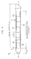
- a filmstrip manufacturing apparatus is adapted to manufacture filmstrips in a format as shown in Fig. 2, wherein each film exposure location 40 is designated by a perforation P.
- the filmstrip 5 has a length L1 which is variable depending on its film frame number N, i.e., the number of the frame exposure locations 40 to be provided in the filmstrip 5.
- the perforations P1 to P N are disposed at constant intervals L2 in a recording section of each individual filmstrip 5. As shown by hatching, both lateral sides of the filmstrip 5 serve as side-print zones 42.
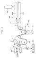
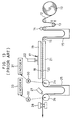
- a long continuous strip of film 12 is fed from a roll 10 through a dancer roller 13, sub-feed rollers 14, a vacuum suction drum 15 and a pass roller 16 into a die set device 45, like the apparatus shown in Fig. 13.
- the die set device 45 is constituted of first to third die sets 46, 47 and 48 which are aligned in continuity along a film transport path, and may be individually actuated.
- the first die set 46 is constituted of a punch holder 46a having fifteen punches 50 arranged at the same interval L2 as the perforations P1 to P N , a dies plate 46b having fifteen dies 51 arranged in correspondence with the punches 50, and an air cylinder 46c for moving the punch holder 46a downward.
- the second and third die sets 47 and 48 are each constituted of a punch holder 47a or 48a having ten punches 50 arranged at the same interval L2 as the perforations P1 to P N , a dies plate 47b or 48b having ten dies 51 arranged in correspondence with the punches 50, and an air cylinder 47c or 48c for moving the punch holder 47a or 48a downward.
- the three die sets 46, 47 and 48 are arranged such that all the punches 50 and the dies 51 as well are spaced at the same interval L2 along the film transport path.
- the die set device 45 can make a series of perforations P1 to P N per one stroke of die-punching while selecting the film frame number N among three variations: 15-exposure, 25-exposure and 35-exposure formats.
- 15-exposure format filmstrips only the first die set 46 is actuated.
- 25-exposure format filmstrips the first and second die sets 46 and 47 are actuated simultaneously.
- 35-exposure format filmstrips all the three die sets 46 to 48 are simultaneously actuated.
- the dies plates 46b, 47b and 48b are stationary, and the same effect is achieved by merely actuating the punch holders 46a, 47a and 48a, the dies plates 46b, 47b and 48b may be replaced by a single dies plate extending over the three punch holders 46a to 48a.
- a film length adjusting mechanism 58 which is constituted of pass rollers 53 and 54, and a movable roller 56 mounted movable in a vertical direction inside a chamber 55 which is disposed between the pass rollers 53 and 54.
- a vacuum suction drum 60 is disposed downstream of the film length adjusting mechanism 58, to transport the long film 12 by a unit length which is predetermined in accordance with the film frame number N.
- the suction drum 60 sucks the long film 12 to not-shown suction holes formed through a peripheral surface of the drum 60.
- the suction drum 60 is driven by a servo motor 61, while an encoder 62 monitors the rotational amount of the suction drum 60 through the servo motor 61.
- the long film 12 is transported from the suction drum 60 to a cutter 28 through a pair of feed rollers 64 and 65 having smaller diameters than the suction drum 60.
- a side-printer 27 is disposed near the feed roller 65 to print film data as character data and bar code data along both lateral sides of the long film 12 in the side-print zone 42 of the individual filmstrips 5 to be formed from the long film 12.
- the cutter 28 cuts off the individual filmstrips 5 from the long film 12 at the variable length L1.
- the cutter 28 has first and second knife edges 28a and 28b respectively for cutting a trailing end 6 of a films trip 5 and a leading end 7 of an adjacent preceding filmstrip 5 in the long film 12.
- Fig. 5 shows the relationship between the long film 12 and two adjacent filmstrips 5a and 5b to be cut off therefrom.
- a leading end 7a of the preceding filmstrip 5a and a trailing end 6b of the following filmstrip 5b are simultaneously cut by the edges 28b and 28a of the cutter 28, respectively. Since a trailing end 6a of the preceding filmstrip 5a has been cut at the preceding cutting stroke, the filmstrip 5a is cut off from the film 12 when its leading end 7a is cut by the edge 28b.
- the cutter 28 preferably has a pair of punches in addition to the knife edges 28a and 28b to provide engaging holes 9 concurrently with cutting the long film 12 into individual filmstrip 5, the engaging holes 9 being used to secure the trailing end 6 to a spool of a photographic film cassette.
- the film length adjusting mechanism 58 is adapted to adjust the length of the film 12 extending between a cut position B defined by the knife edge 28a of the cutter 28 and a punching position A defined by the leftmost punch and die 50a and 51a of the first die set 46 in Fig. 4.
- the movable roller 56 is movably mounted to a supporting block 70 which is movable along a pair of vertical guide shaft 71.
- a timing belt 72 is securely connected to the supporting block 70, and is suspended between teethed pulleys 73 and 74.
- the pulley 74 is driven by a servo motor 75 to move the supporting block 70 and thus the movable roller 56 in the vertical direction.
- An encoder 76 is connected to the other pulley 73 to detect position of the movable roller 56.
- the movable roller 56 may be stopped at one of three predetermined positions X, Y and X, as is shown in Fig.
- a film buffer length such that the length of the film 12 extending from the cut position B to the punching position A, hereinafter referred to as a film buffer length, is set at a value determined based on the unit length L4 for the designated kind of filmstrip, and a film trailer length L3 as well.
- the film trailer length L3 is the length from the trailing end 6 to a first perforation P1 of the individual filmstrip 5, which is to be formed by the die and punch 50a and 51b at the punching position A.
- the length of the film 12 between a trailing end 6 being positioned at the cut position B, on one hand, and a trailing end 6 of a filmstrip 5 being positioned in the die set device 45, on the other hand is set at a value an integral number M of times as long as the unit length L4 for the designated kind filmstrips. Accordingly, it is possible to actuate the die set device 45 and the cutter 28 in synchronism with each other each time the film 12 stops after being transported by the unit length L4.
- the movable roller 56 is moved in the position X when manufacturing 15-exposure filmstrips from the film 12, to set the film buffer length M times as long as a unit length L4a for 15-exposure filmstrip, plus the film trailer length L3, that is, L4a x M + L3 .
- the movable roller 56 is moved in the position Y, so that the film buffer length becomes M times as long as a unit length L4b for 25-exposure filmstrip, plus the film trailer length L3, that is, L4b x M + L3 .
- the film buffer length is M times as long as a unit length L4c for 35-exposure filmstrip, plus the film trailer length L3, that is, L4c x M + L3 .
- the positioning of the movable roller 56 may be manually executed, so the servo motor 75 is dispensable.
- the position Z of the movable roller 56 to the 15-exposure filmstrips, and the position Y to the 25-exposure filmstrips by using a larger integral number M + ⁇ as a factor to define the film buffer length for the 15-exposure filmstrips than an integral number M which is used as a factor to define the film buffer length for the 25-exposure filmstrips.
- the position X may be assigned to the 35-exposure filmstrips by using a smaller integral number M - ⁇ as a factor to define the film buffer length for the 35-exposure filmstrips.
- the feed rollers 64 and 65 are rotated at the same circumferential speed as that of the suction drum 60 so the film 12 may not be loosened.
- the side-print position C is set in a peripheral position of the feed roller 65 where the film 12 is in tight contact with the roller 65.
- the feed roller 65 has a larger diameter than the other feed roller 64, so as to permit the tight contact.
- the side-printer 27 may be disposed closer to the cutter 28, as is shown in Fig. 8, compared with the case shown in Fig. 14. Accordingly, it is possible to make the distance between the side-print position C and the cut position B equal to or less than the film trailer length L3, as is shown in Fig. 2.
- the distance between the positions B and C may be about 50 mm to 100 mm, preferably 50 mm to 70 mm, and more preferably 60 mm to 70 mm. In this way, when the film 12 stops to be cut by the cutter 28, the print position C is located before or at the first perforation P1 defining the start or front end of the recording section in the film transporting direction. Accordingly, side-printing can be performed without intermediate stops through the recording section of each individual filmstrip.
- pass rollers 67 and 69 in a manner as shown in Fig. 9, instead of the pass roller 54, so that the photosensitive emulsion surface of the film 12 will not contact the suction drum 60.
- This embodiment prevents the photosensitive emulsion surface of the film 12 from being scratched or damaged by sucking.
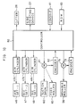
- a controller 80 controls the operation of the above-described apparatus by a controller 80, as shown in Fig. 10.
- a console 81 serves as an input device for the operator to enter the film frame number N of the filmstrips to be manufactured.
- the controller 80 selectively drives the air cylinders 46c, 47c and 48c to actuate the first, or the first and second, or all of the die sets 46, 47 and 48, to form fifteen, twenty-five, or thirty-five perforations at a time, respectively.
- the controller 80 drives the servo motor 61 to rotate the suction drum 60 to transport the film 12 by the unit length L4, which is determined in accordance with the film frame number N, while monitoring output signals from the encoder 62.
- the controller 80 concurrently drives the servo motor 75 to move the movable roller 56 into one of the three positions X, Y and Z in accordance with the film frame number N, while monitoring output signal from the encoder 76.
- the controller 80 also actuates the side-printer 27 and the cutter 28 with respect to the output signal from the encoder 62 under the control of the controller 80.
- the controller 80 sequentially controls the respective parts in accordance with a program stored in a ROM 83.
- the controller 80 actuates the first die set 46 through the air cylinder 46c to make fifteen perforations P1 to P15 through the film 12. Simultaneously, the cutter 28 is actuated to cut a portion of the film 12 where no perforation is made. Thereafter, the film 12 is transported by the unit length L4a for 15-exposure filmstrip.
- the trailing end 6 of the filmstrip 5 having the fifteen perforations in its recording section is placed in the cut position B. Simultaneously therewith, the next recording section to be perforated is placed between the punch holder 46a and the dies plate 46b of the first die set 46. Then, the controller 80 stops transporting the film 12, and actuates the cutter 28 and the first die set 46 at the same time.
- the film 12 is transported by the unit length L4a, and then the first die set 46 is actuated and, simultaneously, the cutter 28 is actuated to cut the trailing end 6 of the next filmstrip 5 and the leading end 7 of the filmstrip 5 whose trailing end 6 has previously been cut.
- the filmstrip 5 with fifteen perforations is cut off the film 12 into an individual 15-exposure filmstrip. In this way, die-punching and cutting are performed in synchronism with each other.
- the side-printer 27 While the film 12 is transported by the unit length L4a after each cutting, the side-printer 27 starts printing when the front end of the recording section immediately after the first perforation P1 is located in the print position C, and continuously print data of 15-exposure filmstrip along the side-print zone 42 in the recording section.
- the side-printer 27 is disposed relative to the cutter 28 such that the side-printer 27 can start printing immediately after the start of film transport.
- the first and second die sets 46 and 47 are simultaneously actuated to make twenty-five perforations P1 to P25 at a time through the film 12 and, thereafter, the suction drum 60 is driven to transport the film 12 by the unit length L4b for 25-exposure filmstrip. Since the leading end and the trailing end of two adjacent filmstrips having fifteen perforations P1 to P15 formed therethrough are cut by the cutter 28 in synchronism with the die-punching of the first and second die sets 46 and 47, the preceding one of the two filmstrips is cut off the film 12 into an individual 15-exposure filmstrip. But the leading end of the following filmstrip is transported farther than the cutter 28 as a result of the rotation of the suction drum 60 by the unit length L4b for 25-exposure filmstrip.
- the film buffer length is L4 + L3 for any film frame number N, by selecting a factor "1" to multiply the unit length L4 in the above-described definition. In this way, merely a defective filmstrip will be produced at each film frame number change.
- die-punching of the first and second die sets 46 and 47 and cutting of the cutter 28 are repeated in synchronism with each other, and the side-printer 27 prints data of 25-exposure filmstrip along the side-print zone 42 while the film 12 is transported by the unit length L4b after each die-punching, in the same way as above, to produce 25-exposure filmstrips.
- the movable roller 56 is moved to the position Z to adjust the film buffer length to the unit length L4c for 35-exposure filmstrip. Then, the first to third die sets 46 to 48 are simultaneously actuated to make thirty-five perforations P1 to P35 at a time. Thereafter, the suction drum 60 is driven to transport the film 12 by the unit length L4c, while the side-printer 27 prints data of 35-exposure filmstrip along the side-print zone 42. The same operation is repeated to produce 35-exposure filmstrips in continuous succession.
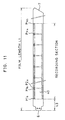
- the present invention is applicable to a case where a pair of perforations P1a and P1b; P2a and P2b; ... P N a and P N b are provided for each frame exposure location, as is shown in Fig. 11.
- Two perforations for assigning longitudinal ends of each frame exposure location facilitate more accurate positioning of the frame exposure location in the exposure aperture of the camera. It is also possible to dispose a pair of perforations on opposite lateral sides of each frame exposure location.
- the air cylinders 46c, 47c and 48c are selectively driven by the controller 80 for each die-punching stroke of the associated die sets 46 to 48, it is also possible to provide a cam 90 and a lever 91, as is shown in Fig. 12, for actuation of each punch holder 93.
- the lowermost position of the punch holder 93 in the die-punching stroke is changed over by an air cylinder 92 connected to the punch holder 93, between an active position and an inactive position.
- the cam 90 is connected to the air cylinder 92 through the lever 91.
- the lever 91 has a cam follower 95 at its one end, the cam follower 95 being always contacted against the cam surface of the cam 90, and is connected to the air cylinder 92 at the opposite end, with its fulcrum 94 disposed in an intermediate position.
- one rotation of the cam 90 causes one stroke of the punch holder 93.
- the punch holder 93 cannot perforate the film 12 placed on a dies plate 96.
- Fig. 12 shows only one punch holder 93, a plurality of such punch holders 93 are disposed along the film 12, and only those punch holders 93 which are set in the active position by the associated air cylinders 92 can effect die-punching by one stroke. This embodiment is suitable for faster die-punching operation.
- cam 90 and the lever 91 are provided for each die set, and are actuated in synchronism with one another in the above-embodiment, it is possible to actuate a plurality of punch holders with air cylinders by a single cam and a lever.
- the present invention is not only applicable to manufacturing photographic filmstrips, but also to manufacturing other kinds of strips or webs from a long strip of resin film or paper.
Landscapes
- Life Sciences & Earth Sciences (AREA)
- Forests & Forestry (AREA)
- Engineering & Computer Science (AREA)
- Mechanical Engineering (AREA)
- Projection-Type Copiers In General (AREA)
- Perforating, Stamping-Out Or Severing By Means Other Than Cutting (AREA)
Applications Claiming Priority (3)
| Application Number | Priority Date | Filing Date | Title |
|---|---|---|---|
| JP143320/94 | 1994-06-24 | ||
| JP14332094 | 1994-06-24 | ||
| JP14332094A JP3368992B2 (ja) | 1994-04-26 | 1994-06-24 | 写真フイルムの穿孔及び切断装置 |
Publications (3)
| Publication Number | Publication Date |
|---|---|
| EP0691190A2 true EP0691190A2 (de) | 1996-01-10 |
| EP0691190A3 EP0691190A3 (de) | 1996-06-05 |
| EP0691190B1 EP0691190B1 (de) | 2000-09-27 |
Family
ID=15336048
Family Applications (1)
| Application Number | Title | Priority Date | Filing Date |
|---|---|---|---|
| EP95109838A Expired - Lifetime EP0691190B1 (de) | 1994-06-24 | 1995-06-23 | Vorrichtung zur Herstellung von fotografischen Filmen |
Country Status (2)
| Country | Link |
|---|---|
| EP (1) | EP0691190B1 (de) |
| DE (1) | DE69518956T2 (de) |
Cited By (6)
| Publication number | Priority date | Publication date | Assignee | Title |
|---|---|---|---|---|
| CN102259774A (zh) * | 2011-06-27 | 2011-11-30 | 上海博显实业有限公司 | 全自动裁切设备 |
| CN102909747A (zh) * | 2012-10-30 | 2013-02-06 | 常州兆阳光能科技有限公司 | 太阳能电池板用eva裁切装置 |
| WO2016146273A1 (de) * | 2015-03-17 | 2016-09-22 | Krones Ag | Vorrichtung und verfahren zum perforieren eines folienschlauchs und zum etiketieren von flaschen |
| CN110815380A (zh) * | 2019-10-08 | 2020-02-21 | 桐城市华猫软膜有限公司 | 一种高分子膜打孔装置 |
| CN112706223A (zh) * | 2019-10-26 | 2021-04-27 | 南通亚振电力科技有限公司 | 一种用于屏蔽纸加工的打孔机 |
| CN118514148A (zh) * | 2024-05-11 | 2024-08-20 | 温州铭立机械有限公司 | 一种往复式冲孔与裁切装置 |
Families Citing this family (1)
| Publication number | Priority date | Publication date | Assignee | Title |
|---|---|---|---|---|
| DE102013107039A1 (de) * | 2013-07-04 | 2015-01-08 | Deutsches Zentrum für Luft- und Raumfahrt e.V. | Verfahren zum Transport eines flexiblen Quasiendlosmaterials, Anlage, Computerprogramm und elektronische Steuereinheit dafür |
Citations (3)
| Publication number | Priority date | Publication date | Assignee | Title |
|---|---|---|---|---|
| JPS61214999A (ja) | 1985-03-18 | 1986-09-24 | コニカ株式会社 | フイルム穿孔機 |
| US4846418A (en) | 1988-03-25 | 1989-07-11 | Eastman Kodak Company | Film cassette |
| JPH042800Y2 (de) | 1985-03-18 | 1992-01-30 |
Family Cites Families (11)
| Publication number | Priority date | Publication date | Assignee | Title |
|---|---|---|---|---|
| CH554225A (de) * | 1973-09-24 | 1974-09-30 | Heuser Ohg Hans Ed | Vorrichtung zum schneiden von vorbestimmten abschnitten aus einer folienbahn. |
| DE3066701D1 (en) * | 1979-09-17 | 1984-03-29 | Developak Corp | Bag forming apparatus |
| DE3261742D1 (en) * | 1981-03-30 | 1985-02-14 | Nixdorf Computer Ag | Severing device for typewriting and printing apparatus |
| DE3727667A1 (de) * | 1987-08-19 | 1989-03-02 | Ostma Maschinenbau Gmbh | Etikettiervorrichtung |
| DE9017695U1 (de) * | 1990-07-20 | 1991-12-19 | H. Berthold AG, 12247 Berlin | Einrichtung zum Transport und Festhalten von Vorlagen und Aufzeichnungsmaterial |
| JP3002684B2 (ja) * | 1990-07-24 | 2000-01-24 | コニカ株式会社 | フィルム加工装置 |
| US5106017A (en) * | 1991-02-19 | 1992-04-21 | Ray Hicks | Pneumatic film punch |
| US5277571A (en) * | 1992-07-17 | 1994-01-11 | George Schmitt & Co., Inc. | Apparatus for perforation of a sheet material |
| JP2534012B2 (ja) * | 1992-12-07 | 1996-09-11 | 富士写真フイルム株式会社 | 穿孔方法及び装置 |
| JP2500836B2 (ja) * | 1992-12-09 | 1996-05-29 | 富士写真フイルム株式会社 | 穿孔方法及び穿孔装置 |
| EP0698453B1 (de) * | 1992-12-07 | 2002-04-03 | Fuji Photo Film Co., Ltd. | Perforiervorrichtung |
-
1995
- 1995-06-23 DE DE69518956T patent/DE69518956T2/de not_active Expired - Fee Related
- 1995-06-23 EP EP95109838A patent/EP0691190B1/de not_active Expired - Lifetime
Patent Citations (3)
| Publication number | Priority date | Publication date | Assignee | Title |
|---|---|---|---|---|
| JPS61214999A (ja) | 1985-03-18 | 1986-09-24 | コニカ株式会社 | フイルム穿孔機 |
| JPH042800Y2 (de) | 1985-03-18 | 1992-01-30 | ||
| US4846418A (en) | 1988-03-25 | 1989-07-11 | Eastman Kodak Company | Film cassette |
Cited By (7)
| Publication number | Priority date | Publication date | Assignee | Title |
|---|---|---|---|---|
| CN102259774A (zh) * | 2011-06-27 | 2011-11-30 | 上海博显实业有限公司 | 全自动裁切设备 |
| CN102259774B (zh) * | 2011-06-27 | 2014-01-01 | 上海博显实业有限公司 | 全自动裁切设备 |
| CN102909747A (zh) * | 2012-10-30 | 2013-02-06 | 常州兆阳光能科技有限公司 | 太阳能电池板用eva裁切装置 |
| WO2016146273A1 (de) * | 2015-03-17 | 2016-09-22 | Krones Ag | Vorrichtung und verfahren zum perforieren eines folienschlauchs und zum etiketieren von flaschen |
| CN110815380A (zh) * | 2019-10-08 | 2020-02-21 | 桐城市华猫软膜有限公司 | 一种高分子膜打孔装置 |
| CN112706223A (zh) * | 2019-10-26 | 2021-04-27 | 南通亚振电力科技有限公司 | 一种用于屏蔽纸加工的打孔机 |
| CN118514148A (zh) * | 2024-05-11 | 2024-08-20 | 温州铭立机械有限公司 | 一种往复式冲孔与裁切装置 |
Also Published As
| Publication number | Publication date |
|---|---|
| DE69518956T2 (de) | 2001-02-01 |
| EP0691190A3 (de) | 1996-06-05 |
| DE69518956D1 (de) | 2000-11-02 |
| EP0691190B1 (de) | 2000-09-27 |
Similar Documents
| Publication | Publication Date | Title |
|---|---|---|
| US6003420A (en) | Apparatus for manufacturing photographic filmstrips | |
| US6334378B1 (en) | Perforator | |
| EP0672937B1 (de) | Zubringervorrichtung von photographischem Material | |
| US4574563A (en) | Method and apparatus for producing photographic film | |
| US6257112B1 (en) | Apparatus for manufacturing photographic filmstrips | |
| EP0691190B1 (de) | Vorrichtung zur Herstellung von fotografischen Filmen | |
| US4314757A (en) | Photographic printer with automatic paper splice detector | |
| US3807855A (en) | Method and apparatus for marking photographic print strips | |
| US7167770B1 (en) | Method of correcting transfer of a thin material and a thin material transfer apparatus | |
| JPH043540B2 (de) | ||
| US4193329A (en) | Photographic paper cutter with damage avoidance back step motion | |
| EP0617327B1 (de) | Photographisches Entwicklungsgerät | |
| JP2500836B2 (ja) | 穿孔方法及び穿孔装置 | |
| JPH0777744A (ja) | 写真処理装置 | |
| EP0762191A1 (de) | Verfahren zum Vor- und Rückspulen photoempfindlichen Materials | |
| JP2002277981A (ja) | 画像記録装置および自動現像処理装置 | |
| JP3358036B2 (ja) | 写真フィルム穿孔装置 | |
| JP2561559B2 (ja) | ロータリーカメラのマーク写し込み装置 | |
| JP2566490B2 (ja) | ロータリーカメラのジャムマーク写し込み装置 | |
| JPH07261281A (ja) | 写真感光材料の供給装置 | |
| JP2004205753A (ja) | 写真焼付装置 | |
| JPH0241730B2 (de) | ||
| JPH0980630A (ja) | 写真処理装置における感光材料の送り出し方法 | |
| JPH10307341A (ja) | 写真焼付装置 | |
| JP2000089444A (ja) | カットマーク検出装置 |
Legal Events
| Date | Code | Title | Description |
|---|---|---|---|
| PUAI | Public reference made under article 153(3) epc to a published international application that has entered the european phase |
Free format text: ORIGINAL CODE: 0009012 |
|
| AK | Designated contracting states |
Kind code of ref document: A2 Designated state(s): DE NL |
|
| PUAL | Search report despatched |
Free format text: ORIGINAL CODE: 0009013 |
|
| AK | Designated contracting states |
Kind code of ref document: A3 Designated state(s): DE NL |
|
| 17P | Request for examination filed |
Effective date: 19960827 |
|
| 17Q | First examination report despatched |
Effective date: 19990128 |
|
| GRAG | Despatch of communication of intention to grant |
Free format text: ORIGINAL CODE: EPIDOS AGRA |
|
| 17Q | First examination report despatched |
Effective date: 19990128 |
|
| GRAG | Despatch of communication of intention to grant |
Free format text: ORIGINAL CODE: EPIDOS AGRA |
|
| GRAH | Despatch of communication of intention to grant a patent |
Free format text: ORIGINAL CODE: EPIDOS IGRA |
|
| GRAH | Despatch of communication of intention to grant a patent |
Free format text: ORIGINAL CODE: EPIDOS IGRA |
|
| GRAA | (expected) grant |
Free format text: ORIGINAL CODE: 0009210 |
|
| AK | Designated contracting states |
Kind code of ref document: B1 Designated state(s): DE NL |
|
| REF | Corresponds to: |
Ref document number: 69518956 Country of ref document: DE Date of ref document: 20001102 |
|
| EN | Fr: translation not filed | ||
| PLBE | No opposition filed within time limit |
Free format text: ORIGINAL CODE: 0009261 |
|
| STAA | Information on the status of an ep patent application or granted ep patent |
Free format text: STATUS: NO OPPOSITION FILED WITHIN TIME LIMIT |
|
| 26N | No opposition filed | ||
| PG25 | Lapsed in a contracting state [announced via postgrant information from national office to epo] |
Ref country code: NL Free format text: LAPSE BECAUSE OF NON-PAYMENT OF DUE FEES Effective date: 20020101 |
|
| NLV4 | Nl: lapsed or anulled due to non-payment of the annual fee |
Effective date: 20020101 |
|
| PGFP | Annual fee paid to national office [announced via postgrant information from national office to epo] |
Ref country code: DE Payment date: 20080626 Year of fee payment: 14 |
|
| PG25 | Lapsed in a contracting state [announced via postgrant information from national office to epo] |
Ref country code: DE Free format text: LAPSE BECAUSE OF NON-PAYMENT OF DUE FEES Effective date: 20100101 |