EP0691277A2 - Récipient empilable - Google Patents
Récipient empilable Download PDFInfo
- Publication number
- EP0691277A2 EP0691277A2 EP95108895A EP95108895A EP0691277A2 EP 0691277 A2 EP0691277 A2 EP 0691277A2 EP 95108895 A EP95108895 A EP 95108895A EP 95108895 A EP95108895 A EP 95108895A EP 0691277 A2 EP0691277 A2 EP 0691277A2
- Authority
- EP
- European Patent Office
- Prior art keywords
- container
- container body
- section
- container according
- support surface
- Prior art date
- Legal status (The legal status is an assumption and is not a legal conclusion. Google has not performed a legal analysis and makes no representation as to the accuracy of the status listed.)
- Granted
Links
- 238000006073 displacement reaction Methods 0.000 claims abstract description 40
- 230000002093 peripheral effect Effects 0.000 claims description 7
- 239000000463 material Substances 0.000 claims description 6
- 239000012779 reinforcing material Substances 0.000 claims description 3
- 238000010276 construction Methods 0.000 description 9
- 230000004323 axial length Effects 0.000 description 3
- 238000007789 sealing Methods 0.000 description 2
- 230000007423 decrease Effects 0.000 description 1
- 230000018109 developmental process Effects 0.000 description 1
- 230000002787 reinforcement Effects 0.000 description 1
- 230000003014 reinforcing effect Effects 0.000 description 1
Images



Classifications
-
- B—PERFORMING OPERATIONS; TRANSPORTING
- B65—CONVEYING; PACKING; STORING; HANDLING THIN OR FILAMENTARY MATERIAL
- B65D—CONTAINERS FOR STORAGE OR TRANSPORT OF ARTICLES OR MATERIALS, e.g. BAGS, BARRELS, BOTTLES, BOXES, CANS, CARTONS, CRATES, DRUMS, JARS, TANKS, HOPPERS, FORWARDING CONTAINERS; ACCESSORIES, CLOSURES, OR FITTINGS THEREFOR; PACKAGING ELEMENTS; PACKAGES
- B65D21/00—Nestable, stackable or joinable containers; Containers of variable capacity
- B65D21/02—Containers specially shaped, or provided with fittings or attachments, to facilitate nesting, stacking, or joining together
- B65D21/0209—Containers specially shaped, or provided with fittings or attachments, to facilitate nesting, stacking, or joining together stackable or joined together one-upon-the-other in the upright or upside-down position
- B65D21/0217—Containers with a closure presenting stacking elements
- B65D21/0222—Containers with a closure presenting stacking elements the closure and the bottom presenting co-operating peripheral ribs and grooves
-
- B—PERFORMING OPERATIONS; TRANSPORTING
- B65—CONVEYING; PACKING; STORING; HANDLING THIN OR FILAMENTARY MATERIAL
- B65D—CONTAINERS FOR STORAGE OR TRANSPORT OF ARTICLES OR MATERIALS, e.g. BAGS, BARRELS, BOTTLES, BOXES, CANS, CARTONS, CRATES, DRUMS, JARS, TANKS, HOPPERS, FORWARDING CONTAINERS; ACCESSORIES, CLOSURES, OR FITTINGS THEREFOR; PACKAGING ELEMENTS; PACKAGES
- B65D21/00—Nestable, stackable or joinable containers; Containers of variable capacity
- B65D21/02—Containers specially shaped, or provided with fittings or attachments, to facilitate nesting, stacking, or joining together
- B65D21/0209—Containers specially shaped, or provided with fittings or attachments, to facilitate nesting, stacking, or joining together stackable or joined together one-upon-the-other in the upright or upside-down position
- B65D21/0213—Containers presenting a continuous stacking profile along the upper or lower edge of at least two opposite side walls
-
- B—PERFORMING OPERATIONS; TRANSPORTING
- B65—CONVEYING; PACKING; STORING; HANDLING THIN OR FILAMENTARY MATERIAL
- B65D—CONTAINERS FOR STORAGE OR TRANSPORT OF ARTICLES OR MATERIALS, e.g. BAGS, BARRELS, BOTTLES, BOXES, CANS, CARTONS, CRATES, DRUMS, JARS, TANKS, HOPPERS, FORWARDING CONTAINERS; ACCESSORIES, CLOSURES, OR FITTINGS THEREFOR; PACKAGING ELEMENTS; PACKAGES
- B65D3/00—Rigid or semi-rigid containers having bodies or peripheral walls of curved or partially-curved cross-section made by winding or bending paper without folding along defined lines
- B65D3/10—Rigid or semi-rigid containers having bodies or peripheral walls of curved or partially-curved cross-section made by winding or bending paper without folding along defined lines characterised by form of integral or permanently secured end closure
- B65D3/12—Flanged discs permanently secured, e.g. by adhesives or by heat-sealing
- B65D3/14—Discs fitting within container end and secured by bending, rolling, or folding operations
Definitions
- the invention relates to a container with a sleeve-shaped container body, with a bottom and a lid for closing the container body and with support surfaces for preventing the horizontal and vertical displacement of stacked, closed containers.
- a container which has a sleeve-shaped container body and a base and which can be closed with a lid.
- Several containers can be stacked on top of one another with the lid closed, one container with the bottom being placed on the essentially flush lid of an adjacent container.
- support surfaces are provided in the known construction, which are intended to prevent the shifting of stacked containers.
- the support surfaces are each arranged on the cover. It is provided here that profiling protruding from the cover should prevent horizontal displacement movements and that the flat surface of the lid defines the position of the container in the vertical direction.
- a bowl or cup-shaped container is known, the opening of which can be closed with a sealing film.
- Several containers can be stacked on top of each other when not closed. When stacking, the container body of one container projects into the container body of an adjacent container and thereby reaches its filling space. Stable stacking of closed containers is not possible.
- This object is achieved in that the support surfaces are arranged such that when containers are stacked, the container body of one container projects into the container body of an adjacent container.
- the support surfaces can be designed and arranged in such a way that the stability of the stack, in particular against lateral tilting, is increased.
- a construction is made possible in which the supporting surfaces of two adjacent containers can nestle against one another when stacked over a sufficiently large surface area. When stacked, the containers are in a position in which they fit into one another over a length range.
- the container body in the sense of the present invention is understood to mean the sleeve-shaped region of the container in its entire axial extent. It does not matter whether the sleeve-shaped area extends over its entire axial extent is formed by a single wall or whether, for example, edges protruding from the lid or the bottom form a longitudinal section of the sleeve-shaped region alone or together with the wall mentioned.
- the lid and / or the bottom of the container In order to allow a container body to protrude into an adjacent container body, the lid and / or the bottom of the container must be arranged sunk in relation to the associated longitudinal end of the container body in the sense of the above definition.
- the container body projecting into an adjacent container body need not touch its recessed lid or bottom, unless one of the supporting surfaces is attached to the lid or the bottom. In any case, a container body does not get into the area of the filling space of an adjacent container body.
- the invention can be used for containers with any cross sections, containers with different cross sections over their length, for example conical containers, also being suitable.
- the support surfaces serving to prevent horizontal displacement are arranged at the two longitudinal ends of the container body in the region of the peripheral edges. This enables a particularly simple construction. Profiling in the area of the floor or lid level is not required.
- the support surfaces are arranged in such a way that a support surface at the first longitudinal end corresponds to a support surface of the second longitudinal end, that is to say that the shape and arrangement of the first and second support surfaces are adapted to one another in such a way that when stacked, the support surface of the first longitudinal end of a container against the corresponding support surface of the second longitudinal end of the adjacent container is coming.
- the mutually corresponding support surfaces are thus shaped and arranged in such a way that they fit together or, for example in the case of a curved shape, fit into one another.
- the container body forms a recess into which the other longitudinal end of an adjacent container can be inserted over a predetermined length when stacked.
- the support surfaces can be arranged on the wall of the container body, the bottom or the lid of the container.
- the lid can be firmly connected to the container body or, for example for reclosing, can be detached from it.
- the lid can be designed in any way. The additional advantage is then obtained that the containers can also be stacked in the open state, the position of the lids being the same as when stacking closed containers.
- the support surfaces are preferably arranged continuously in the circumferential direction of the container body.
- the support surfaces serving to prevent horizontal displacement are arranged in such a way that they extend at least approximately parallel to the axis of the container body. This results in a particularly good stability of the stack against tipping.
- the support surfaces do not need to be arranged exactly in parallel. For example, they can be inclined to the axis of the container or have a curve that is curved transversely to the circumferential direction, for example, they can be curved.
- a first support surface serving to prevent horizontal displacement on the inner circumferential side of a first longitudinal section of the container body located at the first longitudinal end and a second support surface serving to prevent horizontal displacement on the outer circumferential side of a second one located at the second longitudinal end are provided Arrange length section of the container body.
- the two mutually corresponding support surfaces are at the same distance from the axis of the container and, if they are arranged at an incline, assume the same angle of inclination in relation to the axis of the container.
- the container bodies can be supported against one another in the horizontal direction by the relatively large surface area of the adjoining support surfaces.
- the longitudinal sections can have a greater axial extent than the support surfaces arranged with them.
- the longitudinal sections can advantageously be formed by the wall of the container body. However, they can also be formed in each case by an edge section protruding from the cover or the bottom. In this case, the protruding edge section of the lid or of the base can also form the said length section together with the wall of the container body. The edge section can rest on the inside or the outside of the container body.
- the length section can contain an additional, reinforcing material layer, which is formed, for example, by a separate reinforcement ring, the mentioned edge section of the base or the cover or by a bent section of the wall.
- the stability of the stack can be increased further by the additional material layer.
- the support surface arranged in the longitudinal section can be bent over on the wall itself Section of the wall, an edge portion of the lid or the bottom or on a separate reinforcing ring attached to the length portion.
- the first support surface serving to prevent horizontal displacement is arranged in the above-mentioned first length section in such a way that it runs inside a recess on the inner peripheral side of the container body.
- the second support surface for preventing horizontal displacement is arranged in the above-mentioned second length section such that it extends on the outer peripheral side of the container body.
- the first and the second support surface run congruently to one another at the same distance from the axis of the container, so that when two adjacent containers protrude into one another, the first support surface of one container rests against the second support surface of the other container.
- first support surface is arranged on the inner circumferential side in the first length section and the second support surface is arranged on the outer circumferential side in the second length section, it is necessary to arrange the second length section closer to the axis of the container than the first length section. This can be done by arranging the second length section offset in relation to the first length section to the axis of the container body.
- the offset arrangement means that the container body has a smaller outer cross section in the second length section than in the first length section.
- the outer cross section of the second length section corresponds to the inner cross section of the first length section.
- the staggered arrangement can be obtained by a conical, gradually tapering design of the container body.
- the conical container body has the second Longitudinal section has a smaller outer cross section than in the first longitudinal section.
- the container body is also advantageously possible to design the container body to be essentially constant in cross-section over its length, an abrupt radial narrowing being formed in the second length section and / or an abrupt radial expansion in the first length section.
- the abrupt radial narrowing leads to a smaller outer cross section in the second length section.
- the abrupt radial expansion leads to a larger inner cross section in the first length section.
- the length section with the smaller outer cross section for example the region of the radial narrowing of one container, is inserted a little into the recess of the container body of the adjacent container.
- the mutually corresponding supporting surfaces of two adjacent containers which serve to prevent horizontal displacement, lie against each other with a precise fit.
- the support surfaces serving to prevent vertical displacement determine the position of stacked containers in the vertical direction. These support surfaces run at least approximately perpendicular to the axis of the container. This provides particularly good support in the vertical direction.
- the support surfaces do not have to be arranged exactly perpendicular to the axis. For example, they can be inclined to the vertical or have a curve which is curved transversely to the circumferential direction, for example curved.
- Said support surfaces which serve to prevent vertical displacement, can advantageously be arranged in the flat section of the cover and / or the flat section of the bottom. It is possible, for example, that the lid on the The sleeve body is arranged so that the bottom of the adjacent container bears against said lid when stacked.
- the support surfaces serving to prevent vertical displacement are arranged at the two longitudinal ends of the container body in the region of the peripheral edges.
- a first support surface serving to prevent vertical displacement is arranged at the first longitudinal end on the front edge of the container body and a second support surface serving to prevent vertical displacement is arranged on a web protruding from the container body at the second longitudinal end.
- the position of the containers in the vertical direction is determined during stacking without touching the lids or the bases.
- a first support surface serving to prevent vertical displacement is arranged at the first longitudinal end on a flat section of the lid or the bottom and a second support surface serving to prevent vertical displacement is arranged on the front edge of the container body.
- the front edge of the container body rests on the flat portion of the lid or the bottom of the adjacent container.
- the can-shaped container 1 shown in Figure 1 is composed of a sleeve-shaped container body 2, a bottom 3 and a lid 4.
- the container body 2 essentially has the shape of a hollow cylinder, an area with a reduced cross section being formed in a length section to be described further below.
- the cover 4 is fastened to the container body 2 in a known manner at a first longitudinal end 6 and the base 3 at the other, second longitudinal end 7 of the container 1.
- a flat section 12 of the base 3, a flat section 11 of the lid 4 and a wall 13 forming the jacket of the container body 2 together form a cylindrical filling space 5, in which the filling material can be received.
- FIG 1 another container 14 is partially shown, which is identical to the container 1.
- the container 14 is also composed of a container body 15, a base and a cover 17 fastened to a first longitudinal end 16 of the container 14.
- a flat section of the base and a flat section 21 of the lid 17 together with a wall 22 of the container body 15 form a cylindrical filling space 18.
- the two longitudinal ends 6 and 7 of the container 1 and the two longitudinal ends of the container 14, of which only the longitudinal end 16 is shown, are designed so that they allow several containers 1, 14 to be stacked.
- the container 1 is stacked on the identical container 14.
- the second longitudinal end 7 of the container body 2 protrudes a bit into the first longitudinal end 16 of the container body 15.
- the first longitudinal end 6 of the container 1 is designed in the same way as the first longitudinal end 16 of the container 14, so that a further container, not shown in the drawing, could be stacked there.
- the stackability of the containers 1, 14 is made possible, as mentioned, by the special design of the two longitudinal ends 6 and 7 or 16 of the containers 1, 14, which is described below.
- the flat section 11 of the cover 4 is sunk a little in the axial direction into the interior of the container body 2, so that a recess in the form of a cylindrical cavity 8 is formed in a first length section 9 adjoining the end edge .
- a first longitudinal section 20 with a cylindrical cavity 19 is also formed on the first longitudinal end 16 of the container 14 by a correspondingly recessed arrangement of the cover 17.
- the first length section 20 with the cylindrical cavity 19 of the container 14 is obtained by correspondingly deforming the wall 22 of the container body 15 and the lid 17.
- the wall 22 of the container body 15 is bent in the direction of the axis 23, so that a radially directed, annular web 30 (see FIG. 2) is obtained, which forms the front edge of the container 14. Following the web 30, the wall 22 is bent over again, in the direction of the recessed flat section 21 of the lid 17 of the container 14, so that a section 31 of the wall 22 extending essentially parallel to the axis 23 is formed.
- the lid 17 is bent away from the filling space 18 in its edge region.
- the resulting edge section 34 of the cover 17, which protrudes from the flat section 21, lies on the inside of the wall 22 and is overlapped by the bent section 31 of the wall 22.
- a section with a plurality of material layers is formed in the first length section 20 of the container body 15.
- the inner cross section of the first length section 20 of the container 14 and thus also the cross section of the cylindrical cavity 19 are determined by the arrangement and the course of the bent section 31.
- the container body 2 of the container 1 has at its second longitudinal end 7 a second longitudinal section 10 with a radial narrowing. As a result, the outer cross section is reduced at this point. The constriction is such that the container 1 with said second length section 10 can be inserted into the cavity 19 formed in the first length section 20 of the container 14.
- the outer cross section of the second length section 10 corresponds to the inner cross section of the first length section 20.
- the second length section 10 with radial narrowing is obtained by correspondingly deforming the wall 13.
- the wall 13 of the container body 2 is bent over in such a way that a ring which projects in the direction of the interior of the container 1 extending web 24 is formed.
- This web 24 is directed radially, that is to say it runs parallel to the flat section 12 of the base 3. It is thus vertical, just like the flat sections 11, 12, 21 of the base 3 and the cover 4, 17 (see FIG. 1) directed to the axis 23 passing through the containers 1, 14.
- the wall 13 is bent again after the web 24, in the direction away from the filling chamber 5.
- a bent section 26 of the wall 13 running parallel to the axis 23 is produced.
- the container 1 Via the axial extent of this section 26, the container 1 has a reduced outer cross-section, so that said second length section 10 with a radial constriction is formed in this area.
- the wall 13 is bent again after the section 26, in the opposite direction, ie in the direction of the filling chamber 5 of the container 1.
- This inner section 27 directed towards the filling chamber 5 lies against the section 26, so that the two sections 26, 27 of the second length section 10 form two layers of material.
- the bottom 3 is provided in its edge region with an edge section 29 which projects from the flat section 12 of the bottom 3.
- the edge section 29 bears against the inside of the wall 13 and is overlapped by the inner section 27 of the wall 13 directed towards the filling chamber 5 and towards the bottom 3.
- the edge section 29 is connected to the container body 2, preferably by heat sealing.
- the container 1 projects with its second length section 10 into the first length section 20 of the container 14.
- the container body 2 fits snugly against the container body 15.
- a radially directed surface that is to say perpendicular to the axis 23, is formed on the web 30 and is designed as the first support surface 32 of the container 14 against vertical displacement.
- a surface is formed which is parallel to the axis 23 and which runs on the inner circumferential side of the first length section 20, that is to say in the bent section 31, and serves as the first support surface 33 of the container 14 against horizontal displacement.
- a radially directed surface that is to say perpendicular to the axis 23, is formed on the web 24, which is designed as a second support surface 25 for preventing vertical displacement in the container 1.
- a surface is formed which is parallel to the axis 23 and runs on the outer circumferential side of the second longitudinal section 10 and serves as a second supporting surface 28 against horizontal displacement in the container 1.
- the second support surface 28 of the container 1 lies precisely against the first support surface 33 of the container 14. This provides protection against horizontal shifting.
- the second support surface 25 of the container 1 lies precisely against the first support surface 32 of the container 14. In this way a protection against vertical displacement is obtained.
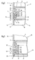
- the containers 35, 44 of FIG. 3 are approximately identical in construction to the containers 1, 14 of FIGS. 1 and 2.
- the containers 35, 44 match the containers 1, 14.
- the container body 45 of the container 44 is thus connected to the lid 17 in the area mentioned, the plane section 21 is directed perpendicular to an axis, not shown in Figure 3, which corresponds to the axis 23 of Figure 1.
- the cover 17 is arranged recessed so that a cavity corresponding to the cavity 8, 19 of FIGS. 1 and 2 is formed.
- the containers 35, 44 differ from the containers 1, 14.
- the container body 36 of the container 35 which is identical in construction to the container 44, has, like the container body 2 of the container 1 shown in FIGS. 1 and 2, a second longitudinal section 38 with a radial narrowing at its second longitudinal end 37.
- This length section 38 also has the same external cross section as the second length section 10 of the container body 2 shown in FIG. 2, which has the radial constriction 39 of the length section 38 has a greater axial length than the corresponding section 26 of the container body 2.
- This greater axial length of the second length section 38 ensures that its end edge 40 extends to the flat section 21 of the cover 17.
- the end edge 40 thus forms a second support surface 41 on its end surface against vertical displacement of the container 35.
- a first support surface 47 is formed against vertical displacement.
- the first support surface 47 and the second support surface 41 bear against one another, so that the vertical position of the containers 35, 44 is fixed.
- a second support surface 42 is fixed against horizontal displacement in the container 35.
- This second The support surface 42 is arranged in the same way as the second support surface 28 of the container 1. It differs from this only in its greater axial length.
- the second support surface 42 lies precisely against the first support surface 33 of the container 44, which has already been described in detail above in connection with FIG. 2. This prevents moving in the horizontal direction.
- the container body is slightly conical, the support surfaces being arranged in the region of a recess and an abrupt radial constriction, as in the embodiments described above.
- the containers 94, 48 of FIG. 4 are approximately identical in construction to the containers 1, 14 of FIGS. 1 and 2. In the area of their first longitudinal ends, of which only the longitudinal end 16 is shown, the containers 94, 48 coincide with the containers 1, 14.
- the containers 94, 48 differ from the containers 1, 14.
- the container body 49 of the container 94 which is identical in construction to the container 48, has, like the container body 2 of the container 1, a second longitudinal section 52 with a radial narrowing at its second longitudinal end 51.
- This length section 52 also has the same outer cross section as the second length section 10 of the container body 2 shown in FIG. 2.
- a vertically directed support surface 53 is arranged in the circumferential direction against horizontal displacement.
- the container body 49 differs from the container body 2 by the different design and arrangement of a base 55 arranged at the second longitudinal end 51.
- the base 55 has a protruding edge with an edge section 56 which is guided into the area of the second length section 52 and there is completely overlapped by a bent section 57 of the wall 13 of the container body 49.
- the second length section 64 of the container body 60 is arranged offset in relation to the first length section 66 of the container body 61 in the direction of an axis (not shown) of the containers 58, 59, which corresponds to the axis 23 of FIG.
- the outside cross section of the second length section 64 corresponds to the inside cross section of the first length section 66.
- the outer cross section of the second length section 64 is not smaller than the outer cross section of the region that adjoins the second length section 64 in the axial direction. There is therefore no radial narrowing.
- the staggered arrangement is obtained by forming a radial extension in the first length section 66. In the area of the first length section 66, the outer cross section of the container body 61 is enlarged in relation to the area adjacent to the first length section 66 in the axial direction.
- a vertically directed second support surface 65 arranged at the second length section 64 bears against a vertically directed support surface 67 arranged at the first length section 66 .
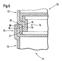
- the containers 70, 71 shown in FIG. 6 have container bodies 72, 73 with an essentially cylindrical shape.
- container bodies 72, 73 Provided at the longitudinal ends 74, 75 of the container body 72, 73 are horizontally directed support surfaces 80, 81, which bear against one another in the mutually projecting position of the containers 70, 71 shown in FIG.
- longitudinal sections 76, 77 which have vertically directed support surfaces 78, 79 which bear against one another in the mutually projecting position of the containers 70, 71.
- the second longitudinal section 76 arranged at the second longitudinal end 74 of the container body 72 is offset in relation to the first longitudinal section 77 arranged at the first longitudinal end 75 of the container body 73 in the direction of the axis of the containers 70, 71.
- the offset arrangement is obtained both by a radial narrowing of the second length section 76 and by a radial expansion of the first length section 77.
- the containers 95, 82 shown in FIG. 7 each have a conical shape.
- the cross section of the container bodies 83, 84 of the containers 95, 82 continuously decreases in the longitudinal direction of the containers 95, 82.
- the second longitudinal section 88 located at the second longitudinal end 85 of the container body 83 has a smaller outer cross section than the first longitudinal section 87 of the container body 84 located at the first longitudinal end 86.
- the one shown in FIG. 7, in relation to the first longitudinal section 87 in the direction of the axis 93 the container body offset 83.84 The arrangement of the second length section 88 results from the conical shape of the containers 95, 82.
- the container 95 projects with its second longitudinal end 85 a little into the first longitudinal end 86 of the container 82.
- a support surface 90 which is arranged at the second length section 88 and is essentially vertical, but slightly inclined in accordance with the taper, bears against a support surface 89 of the first length section 87 which is oriented in the same way.
- a horizontally directed support surface 92 arranged at the second longitudinal end 85 of the container 95 bears against a horizontal support surface 91 arranged in the same way and arranged at the first longitudinal end 86 of the container 82.
- the containers described do not necessarily have to have circular cross sections.
- the cross sections can alternatively also be rectangular, possibly with rounded corners.
- the containers described above are preferably made from blanks made of coated cardboard.
Landscapes
- Engineering & Computer Science (AREA)
- Mechanical Engineering (AREA)
- Stackable Containers (AREA)
- Rigid Containers With Two Or More Constituent Elements (AREA)
Applications Claiming Priority (2)
| Application Number | Priority Date | Filing Date | Title |
|---|---|---|---|
| DE4424244 | 1994-07-09 | ||
| DE19944424244 DE4424244A1 (de) | 1994-07-09 | 1994-07-09 | Stapelbarer Behälter |
Publications (3)
| Publication Number | Publication Date |
|---|---|
| EP0691277A2 true EP0691277A2 (fr) | 1996-01-10 |
| EP0691277A3 EP0691277A3 (fr) | 1996-09-11 |
| EP0691277B1 EP0691277B1 (fr) | 1999-05-06 |
Family
ID=6522748
Family Applications (1)
| Application Number | Title | Priority Date | Filing Date |
|---|---|---|---|
| EP19950108895 Expired - Lifetime EP0691277B1 (fr) | 1994-07-09 | 1995-06-09 | Récipient empilable |
Country Status (4)
| Country | Link |
|---|---|
| EP (1) | EP0691277B1 (fr) |
| JP (1) | JPH08318948A (fr) |
| DE (1) | DE4424244A1 (fr) |
| DK (1) | DK0691277T3 (fr) |
Cited By (1)
| Publication number | Priority date | Publication date | Assignee | Title |
|---|---|---|---|---|
| WO2005113387A3 (fr) * | 2004-05-14 | 2006-11-30 | Ezee Whip Ice Cream Ltd | Contenant alimentaire, appareil de distribution et son procede |
Citations (1)
| Publication number | Priority date | Publication date | Assignee | Title |
|---|---|---|---|---|
| EP0595497A2 (fr) | 1992-10-28 | 1994-05-04 | Dynoplast Limited | Récipients emboîtables avec couvercle |
Family Cites Families (4)
| Publication number | Priority date | Publication date | Assignee | Title |
|---|---|---|---|---|
| US1534803A (en) * | 1921-03-23 | 1925-04-21 | Moore Arlington | Paper container |
| US2100240A (en) * | 1936-04-23 | 1937-11-23 | Julius N Cayo | Container |
| US2310420A (en) * | 1939-10-30 | 1943-02-09 | Graham Duncan Earl | Container |
| DE9211788U1 (de) * | 1992-09-02 | 1993-01-07 | Schmalbach-Lubeca AG, 3300 Braunschweig | Stapelbare dreiteilige Dose aus Blech |
-
1994
- 1994-07-09 DE DE19944424244 patent/DE4424244A1/de not_active Withdrawn
-
1995
- 1995-04-20 JP JP7120926A patent/JPH08318948A/ja active Pending
- 1995-06-09 EP EP19950108895 patent/EP0691277B1/fr not_active Expired - Lifetime
- 1995-06-09 DK DK95108895T patent/DK0691277T3/da active
Patent Citations (1)
| Publication number | Priority date | Publication date | Assignee | Title |
|---|---|---|---|---|
| EP0595497A2 (fr) | 1992-10-28 | 1994-05-04 | Dynoplast Limited | Récipients emboîtables avec couvercle |
Cited By (1)
| Publication number | Priority date | Publication date | Assignee | Title |
|---|---|---|---|---|
| WO2005113387A3 (fr) * | 2004-05-14 | 2006-11-30 | Ezee Whip Ice Cream Ltd | Contenant alimentaire, appareil de distribution et son procede |
Also Published As
| Publication number | Publication date |
|---|---|
| JPH08318948A (ja) | 1996-12-03 |
| DK0691277T3 (da) | 1999-11-01 |
| EP0691277A3 (fr) | 1996-09-11 |
| EP0691277B1 (fr) | 1999-05-06 |
| DE4424244A1 (de) | 1996-01-11 |
Similar Documents
| Publication | Publication Date | Title |
|---|---|---|
| EP0726400B1 (fr) | Dispositif de fixation en matière plastique | |
| DE3345619C2 (fr) | ||
| DE3509641C2 (fr) | ||
| EP0407746A1 (fr) | Réceptacle parallélépipédique à sommet en forme de toit avec un bec verseur sur le toit plat | |
| CH680429A5 (fr) | ||
| EP1428764A1 (fr) | Conteneur empilable | |
| EP1549555A1 (fr) | Contenant de grand volume presentant deux parties et un dispositif de soutien au niveau de la jonction entre les deux parties | |
| EP0685403B1 (fr) | Dispositif de connection | |
| WO1990005095A1 (fr) | Recipient avec une base plane et une surface laterale essentiellement cylindrique | |
| DE102016115215A1 (de) | Seitenwandanordnung für einen Behälter sowie Verfahren zu dessen Herstellung und Behälter mit einer solchen Seitenwandanordnung | |
| EP0691277A2 (fr) | Récipient empilable | |
| DE8705916U1 (de) | Faß aus thermoplastischem Kunststoff | |
| DE4429057A1 (de) | Stapelbarer Deckel für einen Behälter | |
| EP0052803B1 (fr) | Bras de charnière ayant une plaque de montage | |
| DE3532493C1 (en) | Heat exchanger | |
| DE4420807A1 (de) | Höhenverstellbares Stützelement | |
| EP3543158B1 (fr) | Conteneur de transport | |
| WO1997041037A1 (fr) | Dispositif articule pour les sections de paroi pivotantes d'un conteneur | |
| EP3170762A1 (fr) | Conteneur de transport | |
| DE19715453C2 (de) | Dünnwandiges Gefäß | |
| DE9418851U1 (de) | Zylindrischer Behälter mit Deckel | |
| EP1126954B1 (fr) | Boite pour pulverisation | |
| DE1965841A1 (de) | Stapelbarer Behaelter | |
| DE19610391C2 (de) | Kunststoff-Tubenverschluß | |
| DE10051444C2 (de) | Behälterverschluß sowie Verschlußdeckel für diesen Behälterverschluß |
Legal Events
| Date | Code | Title | Description |
|---|---|---|---|
| PUAI | Public reference made under article 153(3) epc to a published international application that has entered the european phase |
Free format text: ORIGINAL CODE: 0009012 |
|
| AK | Designated contracting states |
Kind code of ref document: A2 Designated state(s): DK ES FR IT NL |
|
| 17P | Request for examination filed |
Effective date: 19960215 |
|
| PUAL | Search report despatched |
Free format text: ORIGINAL CODE: 0009013 |
|
| AK | Designated contracting states |
Kind code of ref document: A3 Designated state(s): DK ES FR IT NL |
|
| 17Q | First examination report despatched |
Effective date: 19970714 |
|
| GRAG | Despatch of communication of intention to grant |
Free format text: ORIGINAL CODE: EPIDOS AGRA |
|
| GRAG | Despatch of communication of intention to grant |
Free format text: ORIGINAL CODE: EPIDOS AGRA |
|
| GRAG | Despatch of communication of intention to grant |
Free format text: ORIGINAL CODE: EPIDOS AGRA |
|
| GRAH | Despatch of communication of intention to grant a patent |
Free format text: ORIGINAL CODE: EPIDOS IGRA |
|
| GRAH | Despatch of communication of intention to grant a patent |
Free format text: ORIGINAL CODE: EPIDOS IGRA |
|
| GRAA | (expected) grant |
Free format text: ORIGINAL CODE: 0009210 |
|
| AK | Designated contracting states |
Kind code of ref document: B1 Designated state(s): DK ES FR IT NL |
|
| PG25 | Lapsed in a contracting state [announced via postgrant information from national office to epo] |
Ref country code: IT Free format text: LAPSE BECAUSE OF FAILURE TO SUBMIT A TRANSLATION OF THE DESCRIPTION OR TO PAY THE FEE WITHIN THE PRESCRIBED TIME-LIMIT;WARNING: LAPSES OF ITALIAN PATENTS WITH EFFECTIVE DATE BEFORE 2007 MAY HAVE OCCURRED AT ANY TIME BEFORE 2007. THE CORRECT EFFECTIVE DATE MAY BE DIFFERENT FROM THE ONE RECORDED. Effective date: 19990506 Ref country code: ES Free format text: THE PATENT HAS BEEN ANNULLED BY A DECISION OF A NATIONAL AUTHORITY Effective date: 19990506 |
|
| PGFP | Annual fee paid to national office [announced via postgrant information from national office to epo] |
Ref country code: NL Payment date: 19990630 Year of fee payment: 5 |
|
| ET | Fr: translation filed | ||
| REG | Reference to a national code |
Ref country code: DK Ref legal event code: T3 |
|
| PLBE | No opposition filed within time limit |
Free format text: ORIGINAL CODE: 0009261 |
|
| STAA | Information on the status of an ep patent application or granted ep patent |
Free format text: STATUS: NO OPPOSITION FILED WITHIN TIME LIMIT |
|
| 26N | No opposition filed | ||
| PGFP | Annual fee paid to national office [announced via postgrant information from national office to epo] |
Ref country code: DK Payment date: 20000616 Year of fee payment: 6 |
|
| PGFP | Annual fee paid to national office [announced via postgrant information from national office to epo] |
Ref country code: FR Payment date: 20000626 Year of fee payment: 6 |
|
| PG25 | Lapsed in a contracting state [announced via postgrant information from national office to epo] |
Ref country code: NL Free format text: LAPSE BECAUSE OF NON-PAYMENT OF DUE FEES Effective date: 20010101 |
|
| NLV4 | Nl: lapsed or anulled due to non-payment of the annual fee |
Effective date: 20010101 |
|
| PG25 | Lapsed in a contracting state [announced via postgrant information from national office to epo] |
Ref country code: DK Free format text: LAPSE BECAUSE OF NON-PAYMENT OF DUE FEES Effective date: 20010609 |
|
| REG | Reference to a national code |
Ref country code: DK Ref legal event code: EBP |
|
| PG25 | Lapsed in a contracting state [announced via postgrant information from national office to epo] |
Ref country code: FR Free format text: LAPSE BECAUSE OF NON-PAYMENT OF DUE FEES Effective date: 20020228 |