EP0691478A2 - Dispositif de fixation pour une ferrure ayant un alésage, en particulier pour un élément de charnière - Google Patents
Dispositif de fixation pour une ferrure ayant un alésage, en particulier pour un élément de charnière Download PDFInfo
- Publication number
- EP0691478A2 EP0691478A2 EP95108398A EP95108398A EP0691478A2 EP 0691478 A2 EP0691478 A2 EP 0691478A2 EP 95108398 A EP95108398 A EP 95108398A EP 95108398 A EP95108398 A EP 95108398A EP 0691478 A2 EP0691478 A2 EP 0691478A2
- Authority
- EP
- European Patent Office
- Prior art keywords
- fastening device
- pin
- shaft part
- disc
- socket
- Prior art date
- Legal status (The legal status is an assumption and is not a legal conclusion. Google has not performed a legal analysis and makes no representation as to the accuracy of the status listed.)
- Granted
Links
- 238000010079 rubber tapping Methods 0.000 claims description 14
- 230000002093 peripheral effect Effects 0.000 claims description 12
- 239000002184 metal Substances 0.000 claims description 4
- 229910052751 metal Inorganic materials 0.000 claims description 4
- 230000007704 transition Effects 0.000 claims description 3
- 229910001018 Cast iron Inorganic materials 0.000 claims description 2
- 230000000149 penetrating effect Effects 0.000 abstract 1
- 238000004873 anchoring Methods 0.000 description 6
- 238000003780 insertion Methods 0.000 description 4
- 230000037431 insertion Effects 0.000 description 4
- 229910000831 Steel Inorganic materials 0.000 description 1
- 230000000295 complement effect Effects 0.000 description 1
- 230000006835 compression Effects 0.000 description 1
- 238000007906 compression Methods 0.000 description 1
- 238000007373 indentation Methods 0.000 description 1
- 238000000926 separation method Methods 0.000 description 1
- 239000010959 steel Substances 0.000 description 1
Images



Classifications
-
- F—MECHANICAL ENGINEERING; LIGHTING; HEATING; WEAPONS; BLASTING
- F16—ENGINEERING ELEMENTS AND UNITS; GENERAL MEASURES FOR PRODUCING AND MAINTAINING EFFECTIVE FUNCTIONING OF MACHINES OR INSTALLATIONS; THERMAL INSULATION IN GENERAL
- F16B—DEVICES FOR FASTENING OR SECURING CONSTRUCTIONAL ELEMENTS OR MACHINE PARTS TOGETHER, e.g. NAILS, BOLTS, CIRCLIPS, CLAMPS, CLIPS OR WEDGES; JOINTS OR JOINTING
- F16B12/00—Jointing of furniture or the like, e.g. hidden from exterior
- F16B12/10—Jointing of furniture or the like, e.g. hidden from exterior using pegs, bolts, tenons, clamps, clips, or the like
- F16B12/12—Jointing of furniture or the like, e.g. hidden from exterior using pegs, bolts, tenons, clamps, clips, or the like for non-metal furniture parts, e.g. made of wood, of plastics
- F16B12/20—Jointing of furniture or the like, e.g. hidden from exterior using pegs, bolts, tenons, clamps, clips, or the like for non-metal furniture parts, e.g. made of wood, of plastics using clamps, clips, wedges, sliding bolts, or the like
- F16B12/2009—Jointing of furniture or the like, e.g. hidden from exterior using pegs, bolts, tenons, clamps, clips, or the like for non-metal furniture parts, e.g. made of wood, of plastics using clamps, clips, wedges, sliding bolts, or the like actuated by rotary motion
-
- E—FIXED CONSTRUCTIONS
- E05—LOCKS; KEYS; WINDOW OR DOOR FITTINGS; SAFES
- E05D—HINGES OR SUSPENSION DEVICES FOR DOORS, WINDOWS OR WINGS
- E05D5/00—Construction of single parts, e.g. the parts for attachment
- E05D5/02—Parts for attachment, e.g. flaps
- E05D5/08—Parts for attachment, e.g. flaps of cylindrical shape
-
- F—MECHANICAL ENGINEERING; LIGHTING; HEATING; WEAPONS; BLASTING
- F16—ENGINEERING ELEMENTS AND UNITS; GENERAL MEASURES FOR PRODUCING AND MAINTAINING EFFECTIVE FUNCTIONING OF MACHINES OR INSTALLATIONS; THERMAL INSULATION IN GENERAL
- F16B—DEVICES FOR FASTENING OR SECURING CONSTRUCTIONAL ELEMENTS OR MACHINE PARTS TOGETHER, e.g. NAILS, BOLTS, CIRCLIPS, CLAMPS, CLIPS OR WEDGES; JOINTS OR JOINTING
- F16B12/00—Jointing of furniture or the like, e.g. hidden from exterior
- F16B12/10—Jointing of furniture or the like, e.g. hidden from exterior using pegs, bolts, tenons, clamps, clips, or the like
- F16B12/12—Jointing of furniture or the like, e.g. hidden from exterior using pegs, bolts, tenons, clamps, clips, or the like for non-metal furniture parts, e.g. made of wood, of plastics
- F16B12/20—Jointing of furniture or the like, e.g. hidden from exterior using pegs, bolts, tenons, clamps, clips, or the like for non-metal furniture parts, e.g. made of wood, of plastics using clamps, clips, wedges, sliding bolts, or the like
- F16B12/2009—Jointing of furniture or the like, e.g. hidden from exterior using pegs, bolts, tenons, clamps, clips, or the like for non-metal furniture parts, e.g. made of wood, of plastics using clamps, clips, wedges, sliding bolts, or the like actuated by rotary motion
- F16B12/2027—Jointing of furniture or the like, e.g. hidden from exterior using pegs, bolts, tenons, clamps, clips, or the like for non-metal furniture parts, e.g. made of wood, of plastics using clamps, clips, wedges, sliding bolts, or the like actuated by rotary motion with rotating excenters or wedges
-
- F—MECHANICAL ENGINEERING; LIGHTING; HEATING; WEAPONS; BLASTING
- F16—ENGINEERING ELEMENTS AND UNITS; GENERAL MEASURES FOR PRODUCING AND MAINTAINING EFFECTIVE FUNCTIONING OF MACHINES OR INSTALLATIONS; THERMAL INSULATION IN GENERAL
- F16B—DEVICES FOR FASTENING OR SECURING CONSTRUCTIONAL ELEMENTS OR MACHINE PARTS TOGETHER, e.g. NAILS, BOLTS, CIRCLIPS, CLAMPS, CLIPS OR WEDGES; JOINTS OR JOINTING
- F16B19/00—Bolts without screw-thread; Pins, including deformable elements; Rivets
- F16B19/02—Bolts or sleeves for positioning of machine parts, e.g. notched taper pins, fitting pins, sleeves, eccentric positioning rings
-
- F—MECHANICAL ENGINEERING; LIGHTING; HEATING; WEAPONS; BLASTING
- F16—ENGINEERING ELEMENTS AND UNITS; GENERAL MEASURES FOR PRODUCING AND MAINTAINING EFFECTIVE FUNCTIONING OF MACHINES OR INSTALLATIONS; THERMAL INSULATION IN GENERAL
- F16B—DEVICES FOR FASTENING OR SECURING CONSTRUCTIONAL ELEMENTS OR MACHINE PARTS TOGETHER, e.g. NAILS, BOLTS, CIRCLIPS, CLAMPS, CLIPS OR WEDGES; JOINTS OR JOINTING
- F16B21/00—Means for preventing relative axial movement of a pin, spigot, shaft or the like and a member surrounding it; Stud-and-socket releasable fastenings
- F16B21/02—Releasable fastening devices locking by rotation
-
- A—HUMAN NECESSITIES
- A47—FURNITURE; DOMESTIC ARTICLES OR APPLIANCES; COFFEE MILLS; SPICE MILLS; SUCTION CLEANERS IN GENERAL
- A47B—TABLES; DESKS; OFFICE FURNITURE; CABINETS; DRAWERS; GENERAL DETAILS OF FURNITURE
- A47B2230/00—Furniture jointing; Furniture with such jointing
- A47B2230/0029—Dowels
- A47B2230/0048—Fastening elements comprising plugs, radially expansible by eccentric pins inserted therein
-
- A—HUMAN NECESSITIES
- A47—FURNITURE; DOMESTIC ARTICLES OR APPLIANCES; COFFEE MILLS; SPICE MILLS; SUCTION CLEANERS IN GENERAL
- A47B—TABLES; DESKS; OFFICE FURNITURE; CABINETS; DRAWERS; GENERAL DETAILS OF FURNITURE
- A47B2230/00—Furniture jointing; Furniture with such jointing
- A47B2230/11—Attachment fittings mounted in blind holes
-
- E—FIXED CONSTRUCTIONS
- E05—LOCKS; KEYS; WINDOW OR DOOR FITTINGS; SAFES
- E05D—HINGES OR SUSPENSION DEVICES FOR DOORS, WINDOWS OR WINGS
- E05D5/00—Construction of single parts, e.g. the parts for attachment
- E05D5/02—Parts for attachment, e.g. flaps
-
- E—FIXED CONSTRUCTIONS
- E05—LOCKS; KEYS; WINDOW OR DOOR FITTINGS; SAFES
- E05Y—INDEXING SCHEME ASSOCIATED WITH SUBCLASSES E05D AND E05F, RELATING TO CONSTRUCTION ELEMENTS, ELECTRIC CONTROL, POWER SUPPLY, POWER SIGNAL OR TRANSMISSION, USER INTERFACES, MOUNTING OR COUPLING, DETAILS, ACCESSORIES, AUXILIARY OPERATIONS NOT OTHERWISE PROVIDED FOR, APPLICATION THEREOF
- E05Y2201/00—Constructional elements; Accessories therefor
- E05Y2201/60—Suspension or transmission members; Accessories therefor
- E05Y2201/622—Suspension or transmission members elements
- E05Y2201/638—Cams; Ramps
-
- E—FIXED CONSTRUCTIONS
- E05—LOCKS; KEYS; WINDOW OR DOOR FITTINGS; SAFES
- E05Y—INDEXING SCHEME ASSOCIATED WITH SUBCLASSES E05D AND E05F, RELATING TO CONSTRUCTION ELEMENTS, ELECTRIC CONTROL, POWER SUPPLY, POWER SIGNAL OR TRANSMISSION, USER INTERFACES, MOUNTING OR COUPLING, DETAILS, ACCESSORIES, AUXILIARY OPERATIONS NOT OTHERWISE PROVIDED FOR, APPLICATION THEREOF
- E05Y2600/00—Mounting or coupling arrangements for elements provided for in this subclass
- E05Y2600/50—Mounting methods; Positioning
- E05Y2600/502—Clamping
-
- E—FIXED CONSTRUCTIONS
- E05—LOCKS; KEYS; WINDOW OR DOOR FITTINGS; SAFES
- E05Y—INDEXING SCHEME ASSOCIATED WITH SUBCLASSES E05D AND E05F, RELATING TO CONSTRUCTION ELEMENTS, ELECTRIC CONTROL, POWER SUPPLY, POWER SIGNAL OR TRANSMISSION, USER INTERFACES, MOUNTING OR COUPLING, DETAILS, ACCESSORIES, AUXILIARY OPERATIONS NOT OTHERWISE PROVIDED FOR, APPLICATION THEREOF
- E05Y2600/00—Mounting or coupling arrangements for elements provided for in this subclass
- E05Y2600/50—Mounting methods; Positioning
- E05Y2600/52—Toolless
-
- E—FIXED CONSTRUCTIONS
- E05—LOCKS; KEYS; WINDOW OR DOOR FITTINGS; SAFES
- E05Y—INDEXING SCHEME ASSOCIATED WITH SUBCLASSES E05D AND E05F, RELATING TO CONSTRUCTION ELEMENTS, ELECTRIC CONTROL, POWER SUPPLY, POWER SIGNAL OR TRANSMISSION, USER INTERFACES, MOUNTING OR COUPLING, DETAILS, ACCESSORIES, AUXILIARY OPERATIONS NOT OTHERWISE PROVIDED FOR, APPLICATION THEREOF
- E05Y2600/00—Mounting or coupling arrangements for elements provided for in this subclass
- E05Y2600/60—Mounting or coupling members; Accessories therefor
- E05Y2600/622—Dowels; Pins
-
- E—FIXED CONSTRUCTIONS
- E05—LOCKS; KEYS; WINDOW OR DOOR FITTINGS; SAFES
- E05Y—INDEXING SCHEME ASSOCIATED WITH SUBCLASSES E05D AND E05F, RELATING TO CONSTRUCTION ELEMENTS, ELECTRIC CONTROL, POWER SUPPLY, POWER SIGNAL OR TRANSMISSION, USER INTERFACES, MOUNTING OR COUPLING, DETAILS, ACCESSORIES, AUXILIARY OPERATIONS NOT OTHERWISE PROVIDED FOR, APPLICATION THEREOF
- E05Y2800/00—Details, accessories and auxiliary operations not otherwise provided for
- E05Y2800/26—Form or shape
- E05Y2800/268—Form or shape cylindrical; disc-shaped; circular
-
- E—FIXED CONSTRUCTIONS
- E05—LOCKS; KEYS; WINDOW OR DOOR FITTINGS; SAFES
- E05Y—INDEXING SCHEME ASSOCIATED WITH SUBCLASSES E05D AND E05F, RELATING TO CONSTRUCTION ELEMENTS, ELECTRIC CONTROL, POWER SUPPLY, POWER SIGNAL OR TRANSMISSION, USER INTERFACES, MOUNTING OR COUPLING, DETAILS, ACCESSORIES, AUXILIARY OPERATIONS NOT OTHERWISE PROVIDED FOR, APPLICATION THEREOF
- E05Y2800/00—Details, accessories and auxiliary operations not otherwise provided for
- E05Y2800/26—Form or shape
- E05Y2800/31—Form or shape eccentric
-
- E—FIXED CONSTRUCTIONS
- E05—LOCKS; KEYS; WINDOW OR DOOR FITTINGS; SAFES
- E05Y—INDEXING SCHEME ASSOCIATED WITH SUBCLASSES E05D AND E05F, RELATING TO CONSTRUCTION ELEMENTS, ELECTRIC CONTROL, POWER SUPPLY, POWER SIGNAL OR TRANSMISSION, USER INTERFACES, MOUNTING OR COUPLING, DETAILS, ACCESSORIES, AUXILIARY OPERATIONS NOT OTHERWISE PROVIDED FOR, APPLICATION THEREOF
- E05Y2900/00—Application of doors, windows, wings or fittings thereof
- E05Y2900/20—Application of doors, windows, wings or fittings thereof for furniture, e.g. cabinets
Definitions
- the invention relates to a fastening device for a fitting part provided with a fastening hole, preferably for a hinge part, with a socket which can be inserted into a predrilled hole and in the axially extending, through hole of which a fastening pin, which passes through the fastening hole and is provided with a head, is rotatably mounted.
- Fastening devices of this type are known in different embodiments and mostly consist of a dowel-like bushing which can be inserted into a predrilled hole and which is expanded by anchoring the pin provided with an expansion part to anchor it in the hole.
- a fastening device is known from DE-GM 93 07 086, in which the dowel-like socket is connected to a fastening plate of the fitting part, so that it is only inserted into the predrilled hole when the fitting part is assembled.
- a dowel-like bushing which can be provided with metal parts for better anchoring, is also inserted into a predrilled hole, the bushing for its positive and positive anchoring in the Hole is spread by about a quarter turn of a flattened screw.
- the socket When dismantling the fittings, for example for the purpose of disposing of the furniture parts provided with them, the socket remains in principle in the pre-drilled hole, so that a sorted separation of the components, as is desired in an environmentally friendly disposal, is not possible.
- the object of the invention is to provide an economically producible fastener of the type mentioned, which can be easily and quickly assembled with a tight fit and enables easy and residue-free disassembly.
- this object is achieved in a fastening device of the generic type in that the through hole is arranged eccentrically in the socket or in an annular insert part and in that the pin is provided with an eccentric shaft part which projects beyond the hole and to which a clamping part is fastened.
- the annular insert part and the clamping part are connected to the fitting part by the pin before the assembly.
- the pin is rotated into a position in which the two eccentricities are aligned with one another in such a way that the clamping part does not protrude above the insert part in an axial plan view, so that the bushing or the annular insert part is freely accessible in the hole corresponding to the diameter of the insert part can be used.
- the clamping part By rotating the pin, the clamping part is then moved out of the cylindrical envelope contour of the insert part in the radial direction due to the two eccentricities, so that it engages non-positively and / or positively to anchor the fastening device on the wall of the hole.
- the head To be able to rotate the fastening device, the head is provided with a slot or cross slot. The pin can be anchored by rotating the pin up to approximately 180 degrees.
- the clamping part expediently consists of at least one disk.
- the eccentricities of the insert part and of the shaft part are expediently coordinated with one another in such a way that the disk is concentric with the insert part in one rotational position of the pin or is flush with it, and projects radially beyond the insert part in another rotational position.
- the fastening device according to the invention can not only be installed simply and quickly because the insert part with the clamping part or disc located in its enveloping cylinder can be inserted without hindrance into a predrilled hole, but can also be removed again by simply turning the pin back because the clamping part and the disc can be moved back into the envelope cylinder of the insert and the clamping is completely released.
- the disc is expediently provided with at least one non-running, cutting-like edge.
- Several discs with circumferential cutting edges can also be mounted on the eccentric shaft part.
- the disk is provided with at least one cutting-like, helical thread. This configuration ensures that when the pin rotates, the thread or threads cut into the side wall of the hole and pull the fastening device into the hole due to the rotation of the pin, thereby ensuring a particularly good and tight fit of the Fitting part is reached.
- the eccentric shaft part expediently has a smaller diameter than the shaft part of the pin mounted in the bush.
- the eccentric shaft part can be riveted to the disk or can also be provided with a thread and thereby screwed to the disk.
- the head is provided with a radial extension or projection which cooperates with at least one counter stop in the outer edge region of the fastening bore of the fitting part.
- Appropriate stops ensure that the pin cannot be over-tightened and cannot be turned back further during disassembly than corresponds to the solution of the clamp connection.
- the extension and the counterstop are expediently arranged in such a way that they allow the pin to be rotated by approximately 180 degrees.
- the extension is a nose-shaped projection, which is arranged in a sector-like recess of a holding part of the fitting part made of sheet metal or cast iron.
- This projection can also serve as a pointer that indicates during assembly or disassembly whether the fastening element is in its tensioned or unlocked position.
- the extension can also be a sector-widened edge region which is concentric with the head and whose step-like transitions to the peripheral edge of the head form the stops.
- the disks forming the clamping parts can be trapezoidal in cross section to form the disks. Conveniently the disks have essentially the same diameter as the bushing.
- the attachment of the disc on the eccentric shaft is expediently adapted to the stop positions such that the disc is aligned with the bush in the axial direction when one side of the extension bears against a stop and radially when the other side of the extension bears against the other stop is extended.
- the pin consists of two shaft parts of different diameters, each having eccentric shaft parts, and that the shaft parts penetrate eccentric bores of annular insert parts and the clamping bodies or disks are held on the eccentric shaft parts.
- This embodiment of the invention achieves particularly good anchoring of the fastening element in the bore, since the devices causing the clamping are provided in duplicate.
- the bodies or disks causing the clamping are provided at a greater axial distance from one another, which results in better anchoring in the bore.
- the shaft is connected to a lever located above the mounting hole instead of a head.
- This lever can be moved into the clamping position by hand without tools and, when disassembled, can also be moved back into the open position.
- the lever consists of a plate part that parts of the fitting part, for. B. a mounting flange, flush covered.
- the bushing is provided with a flange which is held non-rotatably with a radial projection in a flange corner of a plate part of the fitting part.
- the shaft part of the pin mounted in the socket is provided with a thread which engages in the wall of the bore of the socket in a self-tapping manner or is screwed into an internal thread of the bore, and that the fastening bore of the fitting part is an elongated hole.
- the shaft of the pin is screwed into the socket simultaneously with the rotation of the pin by about half a rotation, so that it pulls the fitting part to be fastened into contact with a piece of furniture or the like, which with the predrilled hole is provided for insertion in the socket.
- the pin of the fastening device according to the invention is now rotated back by an angle of less than 180 °, the clamping part still engages forcefully and / or positively on the bore wall, so that the fastening device is not yet completely loosened, but the holding head of the Pin due to unscrewing the shaft part so far from the fitting part to be fastened that this can be moved according to the length of the elongated hole for its adjustment before it is fixed by tightening the pin again.
- the pitch of the thread should be selected so that the pin can be turned by less than 180 °. is movable between its position fixing the fitting part and its preassembled position, in which the fitting part can still be moved over the length of the elongated hole.
- two dowel-like sockets are connected to a lower plate, on which a plate-shaped fitting part, which at least partially covers the lower plate, is fastened and is provided with two elongated holes penetrated by the pins with a common center line.
- the fitting part which can consist, for example, of a mounting plate for the hinge arm of a furniture hinge, can be displaced in the direction of the elongated holes aligned with one another.
- the bushings are expediently provided with collar-like projections which engage the edges of the elongated holes in a force-fitting manner, so that the projections bear against the edges of the elongated holes with a certain press fit and the lower plate remains non-positively connected to the fitting part, for example the mounting plate.
- the collar-like projections can essentially only be arranged on sides of the elongated holes lying transversely to the center line, so that only the sides of the parts of the collar-like projections located on opposite sides of the bore bear against the side edges of the elongated holes.
- the width of the diameter of the elongated holes can essentially correspond to the width of the upper shaft part of the pin.
- the bushings are expediently supported with the end faces of base-like elevations on the underside of the plate-shaped fitting part. This is a good fixation of the to be fastened Fitting part reached.
- the fitting part or the mounting plate can be provided with a peripheral edge which is angled towards the furniture part and which corresponds approximately to the height of the base-like elevations and with which the plate-shaped fitting part engages over the lower plate.
- the clamping part is expediently a disc.
- the diameter of the disc is larger than the diameter of the shaft part provided with the thread.
- the diameter of the disk expediently corresponds to the outer diameter of the bush.
- the eccentricities of the socket and the shaft part are expediently coordinated with one another in such a way that the disk is concentric with the socket in one rotational position of the pin or is flush with it and radially projects beyond the socket in another rotational position.
- the fastening device according to the invention can not only be installed simply and quickly because the socket with the clamping part or disc located in its enveloping cylinder can be inserted without hindrance into a predrilled hole, but can also be removed again by simply turning the pin back because the clamping part is caused by this rotation and the washer is moved back into the sleeve sleeve and the clamping is completely released.
- the disc is expediently provided with at least one peripheral, cutting-like edge.
- Several discs with circumferential cutting edges can also be mounted on the eccentric shaft part.
- the disk is provided with at least one cutting-like, helical thread. This configuration ensures that when the pin rotates, the thread or threads cut into the side wall of the predrilled hole and pull the fastening device into the hole due to the rotation of the pin, thereby achieving a particularly good and tight fit of the fitting part.
- the eccentric shaft part expediently has a smaller diameter than the shaft part of the pin mounted in the bush.
- the eccentric shaft part can be riveted to the disk or can also be provided with a thread and thereby screwed to the disk.
- the threaded shaft part of the pin between the head and the disk is longer than the length of the bushing including the projections.
- the shaft part is expediently longer by about half the thread pitch than the bushing, so that the pin can be rotated between its released and its fixed position by a rotation that is less than half a turn. If the pin is turned back in its open position, the disk lies in the open position within the envelope contour of the bush at its lower edge, so that an undesired overturning is avoided.
- the object is achieved according to the invention in a fastening device of the generic type in that the through hole is arranged eccentrically in the socket and in that the pin is provided with an end-side shaft part to which a clamping part is fastened eccentrically and non-rotatably.
- the bushing and the clamping part are connected by the pin to the fitting part to be fastened before assembly.
- the pin is rotated into a position in which the two eccentricities are aligned with one another in such a way that the clamping part does not protrude above the insert part in an axial plan view, so that the bushing can be inserted without hindrance into the hole corresponding to its diameter.
- the clamping part is then moved out of the cylindrical envelope contour of the bushing in the radial direction due to the two eccentricities, so that it engages non-positively and / or positively to anchor the fastening device on the wall of the predrilled hole.
- its head is provided with a slot or cross-slot. The pin can be anchored by rotating the pin up to approximately 180 °.
- the clamping part expediently consists of at least one disk with an eccentric bore.
- the eccentricities of the bushing and the bore are expediently coordinated with one another in such a way that the disk is concentric with the insert in one rotational position of the pin or is flush with it and radially projects beyond the insert in another rotational position.
- the diameter of the disc is expediently equal to the diameter of the socket.
- the diameter of the disc can also be smaller than the diameter of the bush.
- the fastening device according to the invention can not only be installed simply and quickly, because the socket with its clamping cylinder located clamping part or disc can be inserted into a predrilled hole without hindrance, but can also be removed again by simply turning the pin back lets, because by this backward rotation the clamping part or the disc are moved back into the envelope cylinder of the socket and thereby the clamping is completely released.
- the disc is expediently provided with at least one peripheral, cutting-like edge.
- Several discs with circumferential cutting edges can also be mounted on the shaft part.
- the disk is provided with at least one cutting-like, helical thread. This configuration ensures that when the pin or threads turn, the side wall of the pre-drilled hole cut and pull the fastening device into the hole by rotating the pin, thereby achieving a particularly good and firm fit of the fitting part.
- the shaft part carrying the disk with the eccentric bore expediently has a smaller diameter than the shaft part of the pin mounted in the bush.
- the shaft part can be riveted to the disk or can also be provided with a thread and thereby screwed to the disk.
- the bore of the disk expediently has a polygonal profile at least in the region of the rivet head of the shaft part. If the disc is connected to this by riveting the end of the shaft part, the shaft part is compressed, so that it widens and essentially assumes a shape that is complementary to the polygonal profile of the bore, so that not only a non-positive, but also a positive fit Connection of the disc with the shaft part is reached.
- the end of the bushing is expediently provided with an axial extension, the side stops for a radial one Form continuation of the pin.
- the extensions of both the socket and the pin can be sector-shaped.
- the radial extension of the pin can expediently be located at the upper end region of the disk.
- the stops forming the extensions are expediently arranged and designed in such a way that they permit the pin to be rotated in the bushing by approximately 180 ° in order to fully utilize the given eccentricities.
- the shaft part of the pin which is mounted in the socket is provided with a thread which engages in the wall of the bore of the socket in a self-tapping manner or is screwed into an internal thread of the socket.
- the mounting hole of the fitting part is expediently an elongated hole, so that an adjustment of the fitting part is possible.
- the shaft of the pin is thus screwed into the socket simultaneously with the rotation of the pin by approximately half a rotation, so that it pulls the fitting part to be fastened into contact with a furniture part or the like is provided with the pre-drilled hole for inserting the bushing. If the pin is now turned back by an angle of less than 180 °, the clamping part still engages the wall of the bore in a non-positive and / or positive manner, so that the fastening device is not yet completely solved, but the retaining head of the pin due to the unscrewing of the shaft part so far away from the fitting part that this can be moved according to the length of the elongated hole for its adjustment, before it is fixed by tightening the pin again .
- the pitch of the thread is to be chosen so that the pin can be moved between its fixing position and its preassembled position by a rotation that is less than 180 °, in which the fitting part can still be moved over the length of the elongated hole .
- the threaded shaft part of the pin between the head and the disk is longer than the length of the socket including the projections.
- the shaft part is expediently longer by about half the thread pitch than the bushing, so that the pin can be rotated between its released and its fixed position by a rotation that is less than half a turn. If the pin is turned back into its open position, the disk lies in the open position within the envelope contour of the socket at its lower edge, so that an undesired overturning is avoided.
- the envelope contour of the disk is aligned with the cylindrical jacket of the socket when the pin is screwed out of the socket so far that it can be rotated by approximately Can be tightened 180 °.
- This mounting state can be easily achieved in the fastening device according to the invention by screwing the pin into the socket in the required manner and then riveting the disc with the unthreaded shaft part of the pin in a position in which the peripheral contour of the disk is aligned concentrically with the socket or is flush with the jacket of the socket.
- two dowel-like sockets are connected to a lower plate, on which a plate-shaped fitting part, which at least partially covers the lower plate, is fastened and is provided with two elongated holes penetrated by the pins, which lie on a common center line.
- the fitting part which can consist, for example, of a mounting plate for the hinge arm of a furniture hinge, can be displaced in the direction of the elongated holes aligned with one another.
- the bushings are expediently provided with collar-like projections which engage the edges of the elongated holes in a force-fitting manner, so that the projections bear against the edges of the elongated holes with a certain press fit and the lower plate remains non-positively connected to the fitting part, for example the mounting plate.
- the collar-like projections can essentially only be arranged on sides of the elongated holes lying transversely to the center line, so that only the sides of the parts of the collar-like projections located on opposite sides of the bore bear against the side edges of the elongated holes.
- the width of the diameter of the elongated holes can essentially correspond to the width of the upper shaft part of the pin.
- the bushings are expediently supported with the end faces of base-like elevations on the underside of the plate-shaped fitting part. A good fixation of the fitting part to be fastened is thereby achieved.
- the fitting part or the mounting plate can be provided with a circumferential edge, angled against the furniture part, which corresponds approximately to the height of the base-like elevations and with which the plate-shaped fitting part engages over the lower plate.
- the first embodiment of a fastening device shown in FIGS. 1 to 7 consists of a cylindrical bushing 1 with an eccentric through hole 2, the eccentricity of which can be seen in FIG. 6.
- the cylindrical part of the bushing 1 is connected in one piece to an upper, triangular flange 3 with rounded corners, the tip of the triangle being rounded concentrically with the cylindrical main part 1.
- the socket 1 is made of plastic.
- the cylindrical shaft part 4 of a pin 5 is mounted in the bore 2 of the bushing 1.
- the cylindrical shaft part 4 carries a widened head 6, which is provided with a cross recess 7.
- the head 6, which otherwise consists of a circular disk-shaped part, has a radial, nose-shaped projection 8, whose two flanks 9, 10 open tangentially into the circular circumference of the head 6.
- the head 6 lies in a stamped recess 11 of a flange-shaped sheet metal part 12 of the fitting part.
- the stamped indentation 11 has two wall parts 13, 14 which are concentric with the head 6, of which the wall part 13 has approximately the same radius of curvature as the circular disc-shaped part of the head 6, and the wall part 14 has a radius of curvature which corresponds to the extension 8. Between the two concentric wall parts, two straight wall sections opening tangentially into the wall part 13 are provided, which form stops for the flanks 9, 10 of the projection 8, so that the shaft 6 is rotatably held in the recess 11 by
- the shaft part 4 of the pin 5 is continued by an eccentric shaft part 15, the eccentricity being evident from FIGS. 1, 2 and 5.
- an annular steel disk 16 is mounted, which is provided with two helical, cutting threads 17.
- the lower end of the shaft part 15 is provided with a rivet head 18, by means of which the disk 16 and the bushing 11 are held on the flange 12.
- the eccentric shaft part 15 is provided with a thread 19 and the bore of the disk 16 is provided with an internal thread, so that the disk 16 can be screwed onto the eccentric shaft part 19.
- a rounded corner of the flange-shaped edge 3 of the bushing 1 lies in a flanged corner area of the flange 12 in the manner shown in FIG. 3, the straight area connecting the corners being in a straight line Section of the flanged edge rests.
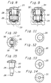
- the eccentricities of the bore 2 and the shaft 15 are aligned with one another in such a way that the cutting-shaped gears 17 lie on the elongated envelope cylinder of the bushing 1 and the bushing 1 with the aligned disk 16 in the correspondingly adapted, predrilled hole 20 can be inserted.
- the pin 21 consists of a first cylindrical shaft part 23 provided with the head 22, a second cylindrical shaft part 24 of smaller diameter concentric with this, an eccentric shaft part 25 arranged between the two shaft parts 23, 24 and an eccentric shaft part 26 continuing the shaft part 24, whereby the eccentric shaft parts 25, 26 each have smaller diameters than the respective shaft parts 23, 24 preceding them.
- the eccentricity of the two shaft parts 25, 26 is rectified and of the same size.
- the disks 30, 31 provided with circumferential cutting edges are held on the eccentric shaft parts 25, 26.
- the fastening bore of the flange-shaped fastening part 32 consists of a flanged bore, the flanged edge being supported on the top of the annular insert part 28 in the manner shown in FIGS. 8 and 9.
- the parts of the fastening device mounted on the pin 21 are held together by a rivet head 33 attached to the end of the eccentric shaft part 26.
- the circular disk-shaped head 34 of the pin 21 consists of two concentric circumferential parts 35, 36 with different radius, the transition between the two circumferential parts being formed by steps 37, 38 which form counter-stops for a stop 39 stamped into the flange 32.
- steps 37, 38 and the embossed stop 39 the pin 21 can be rotated by 180 degrees from the position shown in full lines to the dash-dotted position in the manner shown in FIG. 10.
- FIG. 8 shows the fastening device in its insertion position, in which the peripheral cutting edges of the disks 30, 31 are aligned with the envelope surface of the cylindrical insert parts 28, 29, while FIG. 9 shows the locked position, in which the disks 30, 31 engage in the same direction in a wall part of the pre-drilled hole.
- FIG. 16 and 17 show two further exemplary embodiments of the fastening device, only one cylindrical insert part being provided in each of the two exemplary embodiments, and the fastening device according to FIG. 16 being provided with only one disk and the fastening device according to FIG. 17 with a stack of three disks lying on top of one another is.
- the pin is provided instead of with a head with a lever provided with a plate part 35, so that the lever can be rotated manually between its unlocked and its locked position without a screwdriver.
- the fitting part consists of a so-called “insertion pot” of a two-link hinge, in which the pot-shaped part 36, which can be lowered into a bore, is provided with a fastening flange 37.
- the actuating parts 35, 35 'of the two fastening devices each correspond in their plan view to half of the fastening flange 37, so that the plate parts 35, 35' in their locked position cover the fastening flange 37 approximately with the same edge.
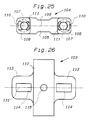
- FIGS. 20 to 26 Another embodiment of the invention will now be explained with reference to FIGS. 20 to 26.
- the fastening plate 102 is fastened to a furniture wall 101 with the fastening device according to the invention.
- the fastening plate 102 consists of a mounting plate 103, for example for the hinge arm of a furniture hinge, and a lower plate 104 covered by this.
- the lower plate 104 consists of an essentially strip-shaped plate part 105, preferably made of plastic, the end regions of which are provided in one piece with dowel-like bushings 106, the eccentric through holes 107 have.
- the lower plate 104 is provided with approximately square base-like elevations 108.
- the mounting plate 103 consists of an elongated central part 112 and cross-shaped connected to this side parts 113, which are provided with rectangular elongated holes 114.
- the width of the elongated holes 114 corresponds to the width of the collar-like projections 110, 111, so that these lie with their lateral edges in the mounting position shown in FIG. 20 non-positively against the lateral edges of the elongated holes 114.
- the mounting plate 103 is provided with a central threaded bore 115 so that a hinge arm or another fitting part can be attached to it.
- the locking pin 116 is held in the eccentric bores 107 of the dowel-shaped bushes 106.
- the pin 116 is provided adjacent to a head 118 provided with a slot or cross slot 117 with a thread-free shaft part 119 and a shaft part 121 with a self-tapping thread 120.
- the shaft part 121 is continued by an eccentric shaft part 122 of reduced thickness, on which the disk 124, which is provided with a self-tapping thread 123 and is provided with a central bore, is placed.
- the end of the shaft part is provided with a rivet head 125 for fastening the disk 124 to the shaft part 122.
- the pin 116 is held with its unthreaded shaft part 119 and the adjoining shaft part 121 provided with the self-tapping thread in the eccentric through bore 107 or the dowel-shaped bushes 106.
- the self-tapping threads 120 cut into the wall of the bore 107 so that the pin can be screwed into and out of the bore over a limited distance.
- the pin 116 is rotated into a position in which the enveloping cylinder of the disk 124 defined by the threads 123 is aligned with the bushing 106.
- the envelope cylinder and the bushing have approximately the same diameter.
- the socket with the aligned disk is inserted into a predrilled blind hole 128 of the furniture plate 101, which has approximately the same diameter as the socket 106.
- the pin 116 is prepared by rotating it by approximately 180 ° from the one on the left in FIG. 20 Mounting position rotated into its locking position shown on the right in FIG. 20. In the locked position, the cutting threads 123 of the disk 124 cut into the side wall of the blind hole 128 in the radial direction.
- the length of the shaft parts 119, 121 of the pin 116 is slightly less than half the pitch of the threads 120 greater than the length of the through-hole 107, so that the pin 116 is screwed into and out of the hole 107 as it rotates this distance can be.
- the head 118 lies on the edges of the elongated hole 114 of the fastening plate 101 and clamps it against the furniture plate 101.
- the fastening plate 103 is provided in the manner shown in FIG. 20 with an edge 130 which is angled against the furniture plate 101 and which can additionally be supported on the furniture plate.
- the pin 116 will be displaced by less than 180 ° Rotation, for example by a rotation of approximately 45 °, is rotated back into its open position so that the cutting threads 123 of the disk 124 still engage in the manner shown in FIG. 21 in a locking manner on the wall of the blind bore 128, the head 118 engages around a small one Distance from the edges of the elongated holes 114 and the adjustment plate 103 can be moved relative to the lower plate 104 in the direction of the double arrow A in Fig. 21 for adjustment.
- the two pins 116 are tightened again by a rotation, for example a quarter turn.
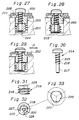
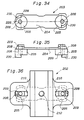
- FIG. 27 to 29 show a cross section through the left wing of the mounting plate shown in FIG. 36 with the fastening device according to the invention, which are shown in different mounting positions.
- the mounting plate 202 covers a lower plate 203 provided with the fastening device and is used for fastening, for example, a hinge arm of a furniture hinge.
- the lower plate 203 consists of an essentially strip-shaped plate part 204, preferably made of plastic, the end regions of which are provided in one piece with dowel-like bushes 205 which have eccentric through holes 206.
- the lower plate 203 On the side opposite the bushes 205 is the lower plate 203 provided with base-like elevations 208, which carry approximately rectangular guide pieces 209 on their top side, which are likewise penetrated by the bores 206.
- elongated holes 210 are provided, the width of which corresponds to the width of the guide pieces 209, which rest with their sides on the edges of the elongated holes 210, so that the mounting plate correspondingly with a loosened fastening device the length of the elongated holes 210 can be moved on the guide pieces 209, the lower edge regions of the elongated holes being supported on the base-like elevations 208.
- the side wings of the mounting plate 202 are provided with a peripheral edge 211, which is flanged in the direction of the furniture part 201, the height of which corresponds to the height of the base-like elevations 208.
- the mounting plate 202 has an elongated central part and is connected in a cross shape to the wing parts, which are provided with the elongated holes 210 on a center line crossing the central part.
- the mounting plate 202 is provided with a central threaded bore 212, which is used to fasten a hinge arm or another fitting part.
- the locking pin 214 is held in the eccentric bores 206 of the dowel-shaped bushes 205.
- the pin 214 is provided adjacent to a slotted or cross-slotted head with a shaft portion 215 which has a self-tapping thread 216.
- the shaft part 215 provided with the self-tapping thread 216 is continued by a thread-free shaft part 217 of reduced thickness.
- the eccentric hole has straight sides 221 spanning a triangle between round bore sections, as can best be seen from FIG. 33.
- the lower plate 204 is inserted into the mounting plate 202 from below in the manner shown in FIG. 36 in such a way that the sides of the guide pieces 209 fit non-positively on the edges of the elongated holes 210.
- the pin 214 is then screwed into the eccentric holes 206 of the dowels 205 to such an extent that the underside of the head of the pin is still at a distance from the top of the wing parts which corresponds to approximately half the pitch of the self-tapping thread 216.
- the lower end of the shaft part provided with the self-tapping thread is in the plane of the lower end face of the bush 205.
- the disk 215 is pushed onto the thread-free shaft part 217 of the pin 214 and aligned so that the envelope cylinder of the disc 219 is flush with the outer surface of the bush 209.
- the lower end of the shaft part 217 is riveted to fasten the disk 219 thereon.
- the rivet head 224 is formed, the lower end of the shaft part 217 undergoes a widening compression, so that at least the shaft part adjoining the rivet head 224 largely fills the polygonal profile 221 of the bore 220 of the disk 219 and the disk 219 is form-fitting and thus non-rotatable with the Shaft part 217 is connected.
- the fastening device is in its assembly position shown in FIG. 27, in which it can be inserted without hindrance into the blind hole predrilled in the furniture part 201.
- the washer 219 is provided at its upper end above the self-tapping thread 218 with a sector-like radial extension 225, the sides 226, 227 of which form stops for counter-stops 228, 229, which are created by the sides of an axial extension 230 of the bushes 205.
- the stops and the counter-stops 226 to 228 are coordinated with one another in such a way that corresponding stops abut one another when the pin is in the mounting position shown in FIG. 27, in which the envelope surface of the disk 219 is flush with the casing of the bush 205, and if, in the other position rotated by approximately 180 °, the disk has been rotated out of the elongated contour of the casing of the bushing 205 by the greatest eccentricity.
- the disk 219 In the locked position shown in FIG. 28, the disk 219 is rotated by approximately 180 ° with respect to the position shown in FIG. 27, so that the cutting threads 218 cut into the wall of the blind hole. In the position shown in FIG. 28, the head of the pin 214 presses the mounting plate against the furniture part 201.
- the pin In the position shown in FIG. 29, the pin has been rotated back by an angle of 180 ° relative to the position shown in FIG. 28, so that the head has been lifted slightly from the mounting plate 202, but without the cutting threads 218 their engagement with the wall of the blind hole have emerged. Due to this reverse rotation, the fastening device has a certain loosening experienced so that the mounting plate 202 can be moved in the direction of the double arrow A for their adjustment. After the desired adjustment, the pin can then be tightened again in the position shown in FIG. 28.
Landscapes
- Engineering & Computer Science (AREA)
- General Engineering & Computer Science (AREA)
- Mechanical Engineering (AREA)
- Connection Of Plates (AREA)
- Hinges (AREA)
- Furniture Connections (AREA)
- Snaps, Bayonet Connections, Set Pins, And Snap Rings (AREA)
- Insertion Pins And Rivets (AREA)
- Pivots And Pivotal Connections (AREA)
- Clamps And Clips (AREA)
- Helmets And Other Head Coverings (AREA)
- Dry Shavers And Clippers (AREA)
- Spinning Or Twisting Of Yarns (AREA)
Applications Claiming Priority (6)
| Application Number | Priority Date | Filing Date | Title |
|---|---|---|---|
| DE4424151 | 1994-07-08 | ||
| DE19944424151 DE4424151C1 (de) | 1994-07-08 | 1994-07-08 | Befestigungsvorrichtung für ein mit einer Befestigungsbohrung versehenes Beschlagteil, vorzugsweise für ein Scharnierteil |
| DE4438285 | 1994-10-26 | ||
| DE19944438285 DE4438285A1 (de) | 1994-07-08 | 1994-10-26 | Befestigungsvorrichtung für ein mit einer Befestigungsbohrung versehenes Beschlagteil |
| DE9420033U | 1994-12-14 | ||
| DE9420033U DE9420033U1 (de) | 1994-12-14 | 1994-12-14 | Befestigungsvorrichtung für ein mit einer Befestigungsbohrung versehenes Beschlagteil, vorzugsweise für ein Scharnierteil |
Publications (3)
| Publication Number | Publication Date |
|---|---|
| EP0691478A2 true EP0691478A2 (fr) | 1996-01-10 |
| EP0691478A3 EP0691478A3 (fr) | 1996-09-18 |
| EP0691478B1 EP0691478B1 (fr) | 1999-08-18 |
Family
ID=27206564
Family Applications (1)
| Application Number | Title | Priority Date | Filing Date |
|---|---|---|---|
| EP95108398A Expired - Lifetime EP0691478B1 (fr) | 1994-07-08 | 1995-05-31 | Dispositif de fixation pour une ferrure ayant un alésage, en particulier pour un élément de charnière |
Country Status (6)
| Country | Link |
|---|---|
| US (1) | US5607271A (fr) |
| EP (1) | EP0691478B1 (fr) |
| JP (1) | JP2643914B2 (fr) |
| AT (1) | ATE183575T1 (fr) |
| DE (1) | DE59506632D1 (fr) |
| ES (1) | ES2137406T3 (fr) |
Cited By (6)
| Publication number | Priority date | Publication date | Assignee | Title |
|---|---|---|---|---|
| FR2782113A1 (fr) * | 1998-08-07 | 2000-02-11 | Franco Ferrari | Charniere a leviers de fixation sur un meuble |
| AT407335B (de) * | 1998-01-08 | 2001-02-26 | Fulterer Gmbh | Dübel zur festlegung von schienen von schubkastenausziehführungen |
| AT407286B (de) * | 1999-01-05 | 2001-02-26 | Blum Gmbh Julius | Möbelbeschlag |
| AT409709B (de) * | 1999-04-19 | 2002-10-25 | Fulterer Gmbh | Schubladenführung |
| EP1275855A1 (fr) * | 2001-07-13 | 2003-01-15 | ALSTOM (Switzerland) Ltd | Pièce pour maintenir des conducteurs de mesure |
| IT201800010821A1 (it) * | 2018-12-05 | 2020-06-05 | Car S R L | Dispositivo ferma-schiena di un mobile rispetto ad una base del mobile stesso e procedimento di assemblaggio del mobile |
Families Citing this family (34)
| Publication number | Priority date | Publication date | Assignee | Title |
|---|---|---|---|---|
| IT1282620B1 (it) * | 1996-02-14 | 1998-03-31 | Franco Ferrari | Dispositivo di regolazione a camma per elementi di ferramenta per mobili ed elementi di ferramenta con esso |
| DE19756635B4 (de) * | 1996-12-21 | 2005-12-15 | Knecht Maschinenbau Gmbh | Messerbolzen zur drehfesten Positionierung eines Kuttermessers an einer Treibscheibe |
| ES2142732B1 (es) * | 1997-10-06 | 2000-12-01 | Ind Aux Es S A | Dispositivo de anclaje para colgadores de muebles de cocina y similares. |
| ES2150355B1 (es) * | 1998-04-21 | 2001-05-01 | Bisagra Tecnica Ind | Dispositivo practicable perfeccionado para la fijacion de bisagras en muebles. |
| DE29915097U1 (de) * | 1999-08-28 | 1999-12-30 | G & G Beschläge GmbH, 72202 Nagold | Verbindungsbeschlag zum Gegeneinanderspannen zweier Teile |
| JP4573931B2 (ja) * | 1999-09-08 | 2010-11-04 | 泰和 楊 | 締結具 |
| US6568894B2 (en) * | 2000-10-04 | 2003-05-27 | Golden Dove Marine | Fastener devices, such as lock-pins |
| FR2850719B1 (fr) * | 2003-01-31 | 2006-12-29 | Peugeot Citroen Automobiles Sa | Agrafe de fixation d'un element de carrosserie sur une structure d'un vehicule automobile |
| US6997658B2 (en) * | 2003-10-20 | 2006-02-14 | Fly David E | Alignment pin and fastener with bi-directional clamping |
| KR101029119B1 (ko) * | 2003-10-27 | 2011-04-13 | 한국항공우주산업 주식회사 | 블라인드 툴링 홀 부싱 |
| ITMI20040446U1 (it) * | 2004-09-30 | 2004-12-30 | Agostino Ferrari Spa | Cerniera con sistema perfezi0nato di fissaggio della vaschetta |
| DE202004018224U1 (de) * | 2004-11-24 | 2005-02-03 | Böllhoff Verbindungstechnik GmbH | Befestigungselement zum Befestigen eines Gegenstandes an einem Aufnahmeteil |
| US8016153B2 (en) * | 2005-08-22 | 2011-09-13 | The Coleman Company, Inc. | Method and apparatus for attaching a lid to an insulated container |
| US20080031702A1 (en) * | 2006-08-01 | 2008-02-07 | Ken-Ching Chen | Fast nail plug |
| CN100523525C (zh) * | 2006-08-03 | 2009-08-05 | 川湖科技股份有限公司 | 快速钉套固定装置 |
| IT1390845B1 (it) * | 2008-07-29 | 2011-10-19 | Leonardo Srl | Gruppo reggipensile regolabile per l'ancoraggio a parete di un mobile pensile |
| IT1391746B1 (it) * | 2008-07-29 | 2012-01-27 | Leonardo Srl | Gruppo reggipensile regolabile per l'ancoraggio a parete di un mobile pensile, con mezzi perfezionati di fissaggio alla spalla del mobile pensile |
| US8267630B2 (en) * | 2009-07-13 | 2012-09-18 | United Technologies Corporation | Threaded flanged bushing for fastening applications |
| US8137039B2 (en) * | 2009-08-06 | 2012-03-20 | King Slide Works Co., Ltd. | Connecting fitting |
| KR101199334B1 (ko) | 2010-04-20 | 2012-11-09 | 한국과학기술연구원 | 체결구 정렬핀 |
| DE102010060618A1 (de) * | 2010-11-17 | 2012-05-24 | Marco Chmielewski | Schraube |
| DE102012109940A1 (de) * | 2012-10-18 | 2014-04-24 | Daimler Ag | Vorrichtung zur Einstellung einer Fuge zwischen Anbauteilen |
| DE102014009257B4 (de) * | 2014-06-20 | 2019-06-19 | Audi Ag | Exzenterelement und Verfahren zum Einstellen einer Relativposition eines Anbauteils |
| KR101465400B1 (ko) * | 2014-06-24 | 2014-11-25 | 정연홍 | 편심 락 어셈블리 |
| US20160059898A1 (en) * | 2014-08-27 | 2016-03-03 | GM Global Technology Operations LLC | Locator cam assembly |
| CN104235143B (zh) * | 2014-10-13 | 2016-06-29 | 湖州现代纺织机械有限公司 | 一种罩壳固定机构 |
| DE102015114401A1 (de) * | 2015-08-28 | 2017-03-02 | Wittenstein Se | Befestigungssystem für ein Maschinenelement |
| JP6475904B2 (ja) * | 2015-09-04 | 2019-02-27 | 株式会社医科歯科技研 | 歯科用インプラント |
| US10144334B2 (en) * | 2017-02-15 | 2018-12-04 | Bnsf Logistics, Llc | Lashing securement pin |
| DE202018106278U1 (de) | 2018-11-05 | 2018-11-16 | Häfele Berlin Gmbh & Co Kg | Verbindungsbolzen zur werkzeuglosen Stoßverbindung zweier Möbelplatten |
| CN109578409A (zh) * | 2019-01-31 | 2019-04-05 | 广西玉柴机器股份有限公司 | 一种定位销偏心衬套 |
| JP7728570B2 (ja) * | 2021-07-27 | 2025-08-25 | オプテックス株式会社 | 締結構造および該構造を備えた物体検出装置 |
| CN216478292U (zh) * | 2021-11-29 | 2022-05-10 | 明劲木业(深圳)有限公司 | 一种家具板件嵌槽式连接固定件 |
| US20230193938A1 (en) * | 2021-12-17 | 2023-06-22 | Raytheon Company | Clean Room Retaining Pin |
Citations (2)
| Publication number | Priority date | Publication date | Assignee | Title |
|---|---|---|---|---|
| DE9307086U1 (de) | 1993-05-12 | 1993-07-01 | Paul Hettich GmbH & Co, 4983 Kirchlengern | An ein Möbelbauteil aus Holz oder einem holzartigen Werkstoff festlegbares Beschlagteil |
| DE4124727C2 (de) | 1991-07-25 | 1994-01-27 | Salice Arturo Spa | Befestigungselement mit einer dübelartigen Buchse |
Family Cites Families (15)
| Publication number | Priority date | Publication date | Assignee | Title |
|---|---|---|---|---|
| US1495913A (en) * | 1923-02-06 | 1924-05-27 | Lobuono Michael | Expansion bolt |
| CH178179A (de) * | 1935-01-03 | 1935-07-15 | Handschin Albisser Albert | Beschlag zum Verschrauben von Kastenteilen. |
| DE2146072A1 (de) * | 1971-09-15 | 1973-04-19 | Hofmann Horst | Schnellverbindung von moebelteilen |
| US3816883A (en) * | 1973-01-04 | 1974-06-18 | Dzus Fastener Co | Fastener |
| JPS5597514A (en) * | 1979-01-17 | 1980-07-24 | Iwata Bolt Kogyo | Driveein nut |
| DE3338976C1 (de) * | 1983-10-27 | 1985-03-07 | Huwil-Werke GmbH Möbelschloß- und Beschlagfabriken, 5207 Ruppichteroth | Möbel - Rückwandverbinder |
| DE3525955A1 (de) * | 1985-07-18 | 1987-01-22 | Le Thanh Son Dipl Ing | Durchsteckverschraubung fuer einseitig zugaengliche verschraubungsstellen |
| DE8620441U1 (de) * | 1986-07-30 | 1986-10-09 | Arturo Salice S.P.A., Novedrate, Como | Grundplatte zur Befestigung eines Scharnierarms eines Möbelscharniers od.dgl. |
| US4696611A (en) * | 1986-04-15 | 1987-09-29 | Albert Guay | Reusable anchor |
| DE3717376A1 (de) * | 1987-05-22 | 1988-12-01 | Grass Alfred Metallwaren | Verstellbare grundplatte fuer scharniere |
| DE8717482U1 (de) * | 1987-07-07 | 1988-12-08 | Arturo Salice S.P.A., Novedrate, Como | Befestigungselement mit einer dübelartigen Buchse |
| US5104141A (en) * | 1991-03-11 | 1992-04-14 | Northstar Manufacturing Company, Inc. | Alignment device for double eccentric CAM arrangement |
| DE9200911U1 (de) * | 1992-01-27 | 1992-03-12 | Huwil-Werke GmbH Möbelschloß- und Beschlagfabriken, 5207 Ruppichteroth | Befestigungsvorrichtung |
| IT1254730B (it) * | 1992-03-23 | 1995-10-10 | Antonio Giovannetti | Dispositivo di ancoraggio,per esempio per componenti di mobili e simili |
| US5310299A (en) * | 1992-09-01 | 1994-05-10 | Kurt Manufacturing Company, Inc. | Sliding clamp |
-
1995
- 1995-05-09 US US08/437,061 patent/US5607271A/en not_active Expired - Lifetime
- 1995-05-31 AT AT95108398T patent/ATE183575T1/de active
- 1995-05-31 DE DE59506632T patent/DE59506632D1/de not_active Expired - Lifetime
- 1995-05-31 ES ES95108398T patent/ES2137406T3/es not_active Expired - Lifetime
- 1995-05-31 EP EP95108398A patent/EP0691478B1/fr not_active Expired - Lifetime
- 1995-07-10 JP JP7173600A patent/JP2643914B2/ja not_active Expired - Fee Related
Patent Citations (2)
| Publication number | Priority date | Publication date | Assignee | Title |
|---|---|---|---|---|
| DE4124727C2 (de) | 1991-07-25 | 1994-01-27 | Salice Arturo Spa | Befestigungselement mit einer dübelartigen Buchse |
| DE9307086U1 (de) | 1993-05-12 | 1993-07-01 | Paul Hettich GmbH & Co, 4983 Kirchlengern | An ein Möbelbauteil aus Holz oder einem holzartigen Werkstoff festlegbares Beschlagteil |
Cited By (12)
| Publication number | Priority date | Publication date | Assignee | Title |
|---|---|---|---|---|
| AT407335B (de) * | 1998-01-08 | 2001-02-26 | Fulterer Gmbh | Dübel zur festlegung von schienen von schubkastenausziehführungen |
| FR2782113A1 (fr) * | 1998-08-07 | 2000-02-11 | Franco Ferrari | Charniere a leviers de fixation sur un meuble |
| US6279200B1 (en) | 1998-08-07 | 2001-08-28 | Franco Ferrari | Hinge with levers for fastening to a piece of furniture |
| GB2340536B (en) * | 1998-08-07 | 2002-09-11 | Ferrari Franco | Hinge with dowel fastening levers |
| AT407286B (de) * | 1999-01-05 | 2001-02-26 | Blum Gmbh Julius | Möbelbeschlag |
| US6287044B1 (en) | 1999-01-05 | 2001-09-11 | Julius Blum Gesellschaft M.B.H. | Fitting |
| AT409709B (de) * | 1999-04-19 | 2002-10-25 | Fulterer Gmbh | Schubladenführung |
| EP1275855A1 (fr) * | 2001-07-13 | 2003-01-15 | ALSTOM (Switzerland) Ltd | Pièce pour maintenir des conducteurs de mesure |
| US6637720B2 (en) | 2001-07-13 | 2003-10-28 | Alstom (Switzerland) Ltd | Component for holding down measuring leads |
| CH695321A5 (de) * | 2001-07-13 | 2006-03-31 | Alstom Technology Ltd | Bauteil zum Niederhalten von Messleitungen. |
| IT201800010821A1 (it) * | 2018-12-05 | 2020-06-05 | Car S R L | Dispositivo ferma-schiena di un mobile rispetto ad una base del mobile stesso e procedimento di assemblaggio del mobile |
| EP3663595A1 (fr) | 2018-12-05 | 2020-06-10 | CAR S.r.l. | Dispositif pour maintenir la position d'un panneau d'un meuble par rapport à une base et procédé d'assemblage d'un meuble |
Also Published As
| Publication number | Publication date |
|---|---|
| EP0691478A3 (fr) | 1996-09-18 |
| JP2643914B2 (ja) | 1997-08-25 |
| US5607271A (en) | 1997-03-04 |
| ES2137406T3 (es) | 1999-12-16 |
| EP0691478B1 (fr) | 1999-08-18 |
| JPH0861332A (ja) | 1996-03-08 |
| DE59506632D1 (de) | 1999-09-23 |
| ATE183575T1 (de) | 1999-09-15 |
Similar Documents
| Publication | Publication Date | Title |
|---|---|---|
| EP0691478B1 (fr) | Dispositif de fixation pour une ferrure ayant un alésage, en particulier pour un élément de charnière | |
| EP0524412B1 (fr) | Elément de fixation avec un manchon construit comme une cheville | |
| AT407777B (de) | Verbindungsbeschlag zum lösbaren verbinden zweier möbelteile | |
| EP0696685A2 (fr) | Elément de fixation | |
| EP1177387A1 (fr) | Element d'assemblage | |
| DE19752714C2 (de) | Befestigungsanordnung für die Anbringung eines Bauteils an einer C-förmigen Halteschiene | |
| DE8717482U1 (de) | Befestigungselement mit einer dübelartigen Buchse | |
| EP0708219A1 (fr) | Ferrure ou similaire, de préférence partie charnière, avec dispositif de fixation | |
| WO1996014513A1 (fr) | Ferrure d'assemblage | |
| DE3436710C2 (de) | Rohrschelle | |
| EP1134170B1 (fr) | Structure à assemblage modulaire pour des rayons de stockage | |
| DE4424151C1 (de) | Befestigungsvorrichtung für ein mit einer Befestigungsbohrung versehenes Beschlagteil, vorzugsweise für ein Scharnierteil | |
| DE102018107083A1 (de) | Befestigungseinrichtung und Verfahren zur Befestigung eines Anbauteils an einem Tragteil, Bauteilsystem und Kraftfahrzeug | |
| DE3531549C2 (de) | Befestigungsvorrichtung für Kraftfahrzeug-Einbauteile, vorzugsweise für Fensterheber | |
| DE2837373C2 (de) | Möbelbeschlagteil, insbesondere Montageplatte für einen Möbelscharnierarm | |
| EP0666426A1 (fr) | Boulon d'expansion | |
| DE19518283C2 (de) | Spreizdübel | |
| DE9420033U1 (de) | Befestigungsvorrichtung für ein mit einer Befestigungsbohrung versehenes Beschlagteil, vorzugsweise für ein Scharnierteil | |
| DE19647209C2 (de) | Befestigungsvorrichtung aus Kunststoff | |
| DE4438285A1 (de) | Befestigungsvorrichtung für ein mit einer Befestigungsbohrung versehenes Beschlagteil | |
| AT411478B (de) | Türband | |
| DE29621873U1 (de) | Montagesystem für die Anbringung eines Bauteils an einer C-förmigen Halteschiene sowie Drehwerkzeug dafür | |
| EP0866231B1 (fr) | Dispositif de fixation préfabriqué | |
| AT396004B (de) | Befestigungselement mit einer duebelartigen buchse | |
| EP1859115A1 (fr) | Ferrure destinee a etre fixee dans une rainure pourvue de contre-depouilles d'un profile de metal ou de plastique |
Legal Events
| Date | Code | Title | Description |
|---|---|---|---|
| PUAI | Public reference made under article 153(3) epc to a published international application that has entered the european phase |
Free format text: ORIGINAL CODE: 0009012 |
|
| AK | Designated contracting states |
Kind code of ref document: A2 Designated state(s): AT DE ES FR GB IT |
|
| PUAL | Search report despatched |
Free format text: ORIGINAL CODE: 0009013 |
|
| AK | Designated contracting states |
Kind code of ref document: A3 Designated state(s): AT DE ES FR GB IT |
|
| 17P | Request for examination filed |
Effective date: 19960909 |
|
| 17Q | First examination report despatched |
Effective date: 19971008 |
|
| GRAG | Despatch of communication of intention to grant |
Free format text: ORIGINAL CODE: EPIDOS AGRA |
|
| GRAG | Despatch of communication of intention to grant |
Free format text: ORIGINAL CODE: EPIDOS AGRA |
|
| GRAG | Despatch of communication of intention to grant |
Free format text: ORIGINAL CODE: EPIDOS AGRA |
|
| GRAH | Despatch of communication of intention to grant a patent |
Free format text: ORIGINAL CODE: EPIDOS IGRA |
|
| GRAH | Despatch of communication of intention to grant a patent |
Free format text: ORIGINAL CODE: EPIDOS IGRA |
|
| GRAA | (expected) grant |
Free format text: ORIGINAL CODE: 0009210 |
|
| AK | Designated contracting states |
Kind code of ref document: B1 Designated state(s): AT DE ES FR GB IT |
|
| REF | Corresponds to: |
Ref document number: 183575 Country of ref document: AT Date of ref document: 19990915 Kind code of ref document: T |
|
| GBT | Gb: translation of ep patent filed (gb section 77(6)(a)/1977) |
Effective date: 19990826 |
|
| REF | Corresponds to: |
Ref document number: 59506632 Country of ref document: DE Date of ref document: 19990923 |
|
| ITF | It: translation for a ep patent filed | ||
| REG | Reference to a national code |
Ref country code: ES Ref legal event code: FG2A Ref document number: 2137406 Country of ref document: ES Kind code of ref document: T3 |
|
| ET | Fr: translation filed | ||
| PLBE | No opposition filed within time limit |
Free format text: ORIGINAL CODE: 0009261 |
|
| STAA | Information on the status of an ep patent application or granted ep patent |
Free format text: STATUS: NO OPPOSITION FILED WITHIN TIME LIMIT |
|
| 26N | No opposition filed | ||
| REG | Reference to a national code |
Ref country code: GB Ref legal event code: IF02 |
|
| PGFP | Annual fee paid to national office [announced via postgrant information from national office to epo] |
Ref country code: FR Payment date: 20120614 Year of fee payment: 18 Ref country code: GB Payment date: 20120523 Year of fee payment: 18 |
|
| GBPC | Gb: european patent ceased through non-payment of renewal fee |
Effective date: 20130531 |
|
| REG | Reference to a national code |
Ref country code: FR Ref legal event code: ST Effective date: 20140131 |
|
| PG25 | Lapsed in a contracting state [announced via postgrant information from national office to epo] |
Ref country code: GB Free format text: LAPSE BECAUSE OF NON-PAYMENT OF DUE FEES Effective date: 20130531 |
|
| PG25 | Lapsed in a contracting state [announced via postgrant information from national office to epo] |
Ref country code: FR Free format text: LAPSE BECAUSE OF NON-PAYMENT OF DUE FEES Effective date: 20130531 |
|
| PGFP | Annual fee paid to national office [announced via postgrant information from national office to epo] |
Ref country code: ES Payment date: 20140526 Year of fee payment: 20 Ref country code: IT Payment date: 20140526 Year of fee payment: 20 Ref country code: DE Payment date: 20140529 Year of fee payment: 20 Ref country code: AT Payment date: 20140505 Year of fee payment: 20 |
|
| REG | Reference to a national code |
Ref country code: DE Ref legal event code: R071 Ref document number: 59506632 Country of ref document: DE |
|
| REG | Reference to a national code |
Ref country code: AT Ref legal event code: MK07 Ref document number: 183575 Country of ref document: AT Kind code of ref document: T Effective date: 20150531 |
|
| REG | Reference to a national code |
Ref country code: ES Ref legal event code: FD2A Effective date: 20150925 |
|
| PG25 | Lapsed in a contracting state [announced via postgrant information from national office to epo] |
Ref country code: ES Free format text: LAPSE BECAUSE OF EXPIRATION OF PROTECTION Effective date: 20150601 |