EP0708219A1 - Ferrure ou similaire, de préférence partie charnière, avec dispositif de fixation - Google Patents
Ferrure ou similaire, de préférence partie charnière, avec dispositif de fixation Download PDFInfo
- Publication number
- EP0708219A1 EP0708219A1 EP95112963A EP95112963A EP0708219A1 EP 0708219 A1 EP0708219 A1 EP 0708219A1 EP 95112963 A EP95112963 A EP 95112963A EP 95112963 A EP95112963 A EP 95112963A EP 0708219 A1 EP0708219 A1 EP 0708219A1
- Authority
- EP
- European Patent Office
- Prior art keywords
- fitting part
- head
- part according
- disc
- retaining pin
- Prior art date
- Legal status (The legal status is an assumption and is not a legal conclusion. Google has not performed a legal analysis and makes no representation as to the accuracy of the status listed.)
- Withdrawn
Links
- 210000004905 finger nail Anatomy 0.000 claims description 3
- 230000002093 peripheral effect Effects 0.000 claims description 2
- 101100327917 Caenorhabditis elegans chup-1 gene Proteins 0.000 description 2
- 230000000295 complement effect Effects 0.000 description 1
- 238000009434 installation Methods 0.000 description 1
- 230000000149 penetrating effect Effects 0.000 description 1
- 230000000630 rising effect Effects 0.000 description 1
- 238000010079 rubber tapping Methods 0.000 description 1
Images


Classifications
-
- A—HUMAN NECESSITIES
- A47—FURNITURE; DOMESTIC ARTICLES OR APPLIANCES; COFFEE MILLS; SPICE MILLS; SUCTION CLEANERS IN GENERAL
- A47B—TABLES; DESKS; OFFICE FURNITURE; CABINETS; DRAWERS; GENERAL DETAILS OF FURNITURE
- A47B95/00—Fittings for furniture
-
- E—FIXED CONSTRUCTIONS
- E05—LOCKS; KEYS; WINDOW OR DOOR FITTINGS; SAFES
- E05D—HINGES OR SUSPENSION DEVICES FOR DOORS, WINDOWS OR WINGS
- E05D5/00—Construction of single parts, e.g. the parts for attachment
- E05D5/02—Parts for attachment, e.g. flaps
- E05D5/08—Parts for attachment, e.g. flaps of cylindrical shape
-
- A—HUMAN NECESSITIES
- A47—FURNITURE; DOMESTIC ARTICLES OR APPLIANCES; COFFEE MILLS; SPICE MILLS; SUCTION CLEANERS IN GENERAL
- A47B—TABLES; DESKS; OFFICE FURNITURE; CABINETS; DRAWERS; GENERAL DETAILS OF FURNITURE
- A47B95/00—Fittings for furniture
- A47B2095/006—Fittings for furniture having dowels and expansion plugs
-
- A—HUMAN NECESSITIES
- A47—FURNITURE; DOMESTIC ARTICLES OR APPLIANCES; COFFEE MILLS; SPICE MILLS; SUCTION CLEANERS IN GENERAL
- A47B—TABLES; DESKS; OFFICE FURNITURE; CABINETS; DRAWERS; GENERAL DETAILS OF FURNITURE
- A47B2230/00—Furniture jointing; Furniture with such jointing
- A47B2230/12—Furniture fittings in two blind holes
-
- E—FIXED CONSTRUCTIONS
- E05—LOCKS; KEYS; WINDOW OR DOOR FITTINGS; SAFES
- E05Y—INDEXING SCHEME ASSOCIATED WITH SUBCLASSES E05D AND E05F, RELATING TO CONSTRUCTION ELEMENTS, ELECTRIC CONTROL, POWER SUPPLY, POWER SIGNAL OR TRANSMISSION, USER INTERFACES, MOUNTING OR COUPLING, DETAILS, ACCESSORIES, AUXILIARY OPERATIONS NOT OTHERWISE PROVIDED FOR, APPLICATION THEREOF
- E05Y2600/00—Mounting or coupling arrangements for elements provided for in this subclass
- E05Y2600/60—Mounting or coupling members; Accessories therefor
- E05Y2600/622—Dowels; Pins
-
- E—FIXED CONSTRUCTIONS
- E05—LOCKS; KEYS; WINDOW OR DOOR FITTINGS; SAFES
- E05Y—INDEXING SCHEME ASSOCIATED WITH SUBCLASSES E05D AND E05F, RELATING TO CONSTRUCTION ELEMENTS, ELECTRIC CONTROL, POWER SUPPLY, POWER SIGNAL OR TRANSMISSION, USER INTERFACES, MOUNTING OR COUPLING, DETAILS, ACCESSORIES, AUXILIARY OPERATIONS NOT OTHERWISE PROVIDED FOR, APPLICATION THEREOF
- E05Y2900/00—Application of doors, windows, wings or fittings thereof
- E05Y2900/20—Application of doors, windows, wings or fittings thereof for furniture, e.g. cabinets
Definitions
- the invention relates to a fitting part or the like, preferably a hinge part with a fastening device.
- a fastening device for a fitting part provided with a fastening hole preferably for a hinge part, which can be inserted into a pre-drilled hole, in the axially extending, continuous hole of a hole passing through the fastening hole , with a head-provided pin is rotatably mounted, the through hole being arranged eccentrically in the bushing or an annular insert part and the pin being provided with an eccentric shaft part projecting beyond the hole, to which a clamping part is attached.
- the head is provided with a slot or a cross recess for the attachment of a screwdriver, so that it can only be fitted with a tool.
- DE-AS 22 31 328 discloses a mounting plate for furniture hinges with at least one fastening pin which can be inserted into a round bore in a furniture wall and which has an eccentric part which, after its rotation, engages in the wall of the bore and which is parallel to the one Mounting plate extending retaining plate is provided, which forms a lever which can be rotated with the fastening pin between its unlocked and its locked position.
- the pivoting angle of this holding plate is limited by stops on the mounting plate, so that this serves to limit the pivoting angle.
- the holding plate In order to be able to rotate the holding plate, it is provided on its side opposite the fastening pin with a slot for attacking a screwdriver, whereby it must be doubted that the fastening plate can only be rotated by hand from its assembly position into the assembled locking position without a screwdriver.
- the object of the invention is to provide a fitting part of the type mentioned that can be easily assembled without special tools.
- the retaining pin of the fitting part according to the invention is provided with an actuating part which is pivotally connected to its upper shaft part or head and is otherwise non-rotatably connected to the upper shaft part or head so that the actuating part can be easily and conveniently moved by hand for the purpose of rotating it after it is folded up can turn the assembled or unlocked position.
- the actuating part can be pivoted again into a plane parallel to the fastening flange or to the fastening plate, so that it does not interfere with appearance.
- the fitting part according to the invention can for example consist of a on the underside of a mounting flange or a plate-shaped Part of the fitting part non-rotatably fastened, insertable into a pre-drilled hole, which is provided with a bore which is essentially aligned with a breakthrough of the fastening flange, from a retaining pin, the widened head of which lies on the top of the fastening flange and the shaft part adjoining the head penetrates the breakthrough, is rotatably mounted in the bore of the bushing and carries an eccentric part which engages in a locking manner on the wall of the hole, and consists of a flat actuating part which is pivotally connected to the head and which is inactive from its essentially parallel to the fastening flange in its to the axis of the retaining pin fold substantially parallel actuation position exist.
- the actuating part expediently consists of a disk with a recess bordered by fork-shaped legs, at the ends of which there are pins which point inwards at right angles and which are pivotably mounted in radial bores or recesses in the region of the head of the holding pin.
- the recesses form slot-like guides for the pins with the upper side of the mounting flange when the shaft part of the holding pin is mounted in the socket and that the legs have a flattened portion on their upper side and that lateral widenings of the head subsequently to the initial area the slot-like guide are provided on their underside with a corresponding flattening, so that the disk can be pushed under the flattening of the head with the flattened parts of its legs in its position in its folded position on the fastening flange.
- the actuating part can be secured to the retaining pin or its head both before assembly and after assembly, that it cannot stand up unintentionally. If the actuating part is to be erected for the purpose of rotating the holding pin, it is necessary beforehand to move it in the radial direction from its locked position parallel to the fastening flange before it can be erected.
- the cutouts in the head can run out freely towards the shaft of the holding pin.
- the pins can be easily inserted into the recesses by pushing them into the recesses from below parallel to the shaft.
- Such assembly is possible in particular because the elongated holes holding the pins are formed between the top of the recess and the outside of the mounting flange through which the retaining pin passes.
- it can be provided on its upper side with a notch for the attachment of a fingernail.
- the mounting flange on its side, in which the disc is folded into the locking position is provided with a ramp which slopes upwards outwards and which, in the inserted position of the disc, corresponds to a corresponding one provided on the underside thereof Recess is covered. If the disc is pulled radially outwards from its locked position, it runs with a wall of its recess over the inclined ramp, so that it can easily be pivoted upwards out of its position parallel to the mounting flange and can therefore be gripped more easily for complete erection.
- the disc can be provided on its underside with lateral tooth-like projections which engage in corresponding recesses in the fastening flange when the position is rotated, folded over and pushed in.
- These tooth-like projections with their flanks rising obliquely outwards also serve to easily erect the pane when it is pulled radially out of its locked position or from its prepared installation position.
- the disk can have an approximately rectangular shape.
- the head is expediently approximately T-shaped, the central web of which corresponds to the width of the recess between the limbs of the disc, so that the head, when the disc is folded and pushed in, complements it with a part with a closed surface.
- the head and the folded-in and pushed-in pane can have an overall rectangular shape which is elegantly integrated into the overall structure.
- the end faces of the limbs of the disk are expediently supported in the actuating position on the fastening flange. In this way it is ensured that the disk cannot inadvertently fold over again after it has been erected for the purpose of rotating the retaining pin.
- the head with a radial extension lies in a recess of the fastening flange or the plate to be fastened, that parts of the peripheral wall of the recess form impacts for the flanks of the extension, so that the retaining pin is only unlocked between it and can turn locked position.
- the holding pin is expediently unlocked between its and its locked position rotated 180 ° so that the stops only allow this rotation.
- the shaft of the holding pin carries an outer eccentric shaft part on which a disk with at least one circumferential cutting edge is held. Furthermore, the shaft can be mounted in an eccentric bore of the bushing, the two eccentricities being matched to one another in such a way that the disk or the like is aligned with the bushing in the assembly position and is extended radially by the amount of both eccentricities in its position rotated by 180 ° .
- the socket is expediently provided at its upper end with at least one upper projection which engages in a corresponding recess in the fastening flange as a means of preventing rotation.
- the retaining pin passing through the fastening flange, the bushing and the washer is provided with a rivet head holding the washer.
- the fastening flange or the plate to be fastened can be easily and permanently connected to the fastening device.
- the head of the holding pin is provided with a slot for attaching a simple tool, for example a coin, instead of with a foldable actuating part.
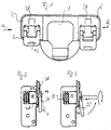
- Fig. 1 shows a conventional hinge cup 1 with side mounting flanges 2, which forms the movable hinge part of a double link hinge.
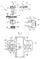
- a fastening device 3 which can best be seen in FIG. 7, is used to fasten the hinge cup 1.
- the fastening device 3 consists of a holding pin 4, which has a specially shaped head part 5 and a cylindrical shaft part 6 adjoining this, which is continued by a smaller diameter eccentric cylindrical shaft part 7.
- the top part 5 is approximately T-shaped in plan view with a compact broad central web 9, which can best be seen from FIG. 1.
- On its underside is the head part 5 with lateral cutouts 10 10, which are best seen in FIG. 10 under the side webs and the central web 9, the mutually parallel inner walls 11 of the recesses 10 tapering tangentially into the shaft part 6.
- the head part 5 is provided with an annular part 12 which is interrupted by the recesses 10 and has a radial nose-shaped bulge 13.
- the shaft 6 of the retaining pin 3 passes through an opening 14 in the flange-shaped part 2, 32, the head-shaped part 5 being supported on the base of a recess 15, the shape of which can best be seen in FIG. 9.
- the recess 15 has two mutually opposite concentric wall parts 16, 17 with different radii of curvature, the wall parts 16, 17 being connected to one another by wall parts formed by straight flanks 18, 19 which enter tangentially into the wall part 16 with a smaller radius of curvature.
- the straight wall parts 18, 19 form stops for the flanks 20, 21 of the radial extension 13 which limit the pivoting angle of the holding pin 3.
- the opening 14 in the flange-shaped parts 2, 32 is provided with radial recesses 23, which engage in the pin-like projections 26 provided on the upper end face of the bushing 25, so that the bushing 25 is held non-rotatably in its assembled position on the underside of the fastening flanges.
- the bush 25 is provided with an eccentric bore 27 which is aligned with the opening 14 of the flange-shaped parts.
- the socket 25 is advantageously made of plastic.
- the retaining pin with its shaft part 6 penetrates the bore 27 of the bushing 25, the disc 28, which is provided with a through-bore, being placed on the eccentric shaft part 7.
- the disk 28 is provided with two self-tapping helical threads 29.
- the eccentric shaft part 7 has a lower rivet head 30 after the disk 28 has been put on provided so that the holding pin with its shaft part 6, the bores 14 and 27 and with its shaft part 7, the bore of the disk 28 penetrating axially fixed and rotatable by about 180 ° on the mounting flange 2, 32 is fixed.
- inwardly facing pins 33 are longitudinally displaceable, which are angled from the side legs 34 of an essentially rectangular actuating plate 35 with rounded corners.
- the pins 33 are inserted into the recess 10 via the shaft 6 before the retaining pin 3 is pushed through the bores of the flange, the bushing and the disk 28 and the unit is riveted to one another so that the pins engage in slot-like guides, which are formed between the upper wall of the recesses 10 and the top of the mounting flanges 2, 32 after mounting the mounting pin 3.
- the legs 34 of the actuating plate 35 are provided in the manner shown in FIG. 7 at their free ends with flats 36 which connect via steps 37 to the thicker part of the actuating plate.
- the fastening flanges 2, 32 are provided on the sides in which the actuating plates 35 are folded onto the fastening flanges in the locking position of the fastening device with ramp-shaped elevations 38 which rise in a wedge-shaped manner to the outside in the manner best seen in FIG. 7.
- the actuating plate 35 is provided on its underside with a recess 39 which is approximately complementary to the ramp-shaped elevation 38, so that the ramp-shaped elevation 38 in the locking position shown in FIG. 5 can be inserted into the recess 39 when the ones provided with the recesses 36 End regions are pushed under the recesses 10 of the head part and the actuating plate 35 is in its locked position parallel to the fastening flange.
- the legs 34 of the actuating plate 35 are further provided on their underside with sawtooth-like projections 40 which, in the locking position shown in FIG. 5, in which the actuating plates are also in their locked position, engage in corresponding recesses 41 in the fastening flanges.
- the actuation plate 35 On its upper side, the actuation plate 35 is provided with a curved notch 43, which is used for the attachment of a fingernail, in order to move the actuation plate from its locked position, which can be seen on the left from FIG. 4 and from FIG. 5, into its locked position from the right in FIG. 4 and in Fig. 6 to move radially extended position, in which the actuating plate 35 to pivot by about 90 ° in its actuating position shown in dash-dotted lines in Fig. 6, in which, by attacking the actuating plate 35, the retaining pin of the fastening device in the desired manner between its locking and unlocked position can be rotated.
- the actuating plate 35 is slightly raised from its position parallel to the mounting flange by the radial extension of the mounting plate 35 from the position shown in FIG. 5 to the position shown in FIG. 6, so that it can be gripped easily with the fingers.
- the fastening device according to the invention is delivered in its mountable position shown on the left in FIG. 1 and in FIG. 2.
- the actuating plate is in its radially inwardly pushed position parallel to the fastening flange 2, in which the cover part 46 of the recess 10 of the head-shaped part 5 is thinned by the recess 36 overlaps front area 47 of leg 34.
- the rear end of the actuating plate 35 projects beyond the edge of the fastening flange 2. If the actuating plate 35 is now pulled radially outward in the direction of arrow F, the fastening plate is oriented somewhat in the manner shown in FIG.
- the retaining pin can be turned by rotating the fastening plate 35 in the direction of the curved arrow from its mounting position shown in FIGS. 2 and 3 into its mounting position shown in FIGS 5 and 6 turn the visible assembled position.
- the cutting passages 29 of the disk 28 cut into the side wall of the fastening hole 49 shown in broken lines. Due to the helical arrangement of the cutting threads 29, the fastening device is additionally drawn into the predrilled hole 49.
- the actuating plate is then folded in the direction of arrow G in FIG. 6 onto the mounting flange and then moved radially inward in the direction of arrow H, so that the mounting plate comes into its locked, assembled position shown in FIG. 5.
- the legs 34 enclose the wide T-web 9 of the head part 5 in the manner evident from the left side of FIG. 4, so that the actuating plate 35 fits in elegantly into the overall structure of the fitting part.
- FIGS. 11 to 14 Another embodiment of the fastening device according to the invention can be seen from FIGS. 11 to 14.
- the shaft part 6 and the latter eccentrically continuing shaft part 7 of the retaining pin 50 has the same configuration as in the exemplary embodiment according to FIG. Fig. 7, so that reference can be made to the description of the first embodiment.
- the head of the holding pin 50 is designed as a widened plate 51 with the shape shown in FIGS. 11 and 14, a transverse elevation 52 being provided on the top of the head 51, which is provided with a slot 53 for the use of a screwdriver or a coin is.
Landscapes
- Engineering & Computer Science (AREA)
- Mechanical Engineering (AREA)
- Hinges (AREA)
- Pivots And Pivotal Connections (AREA)
Applications Claiming Priority (2)
| Application Number | Priority Date | Filing Date | Title |
|---|---|---|---|
| DE4437470A DE4437470C1 (de) | 1994-10-19 | 1994-10-19 | Beschlagteil, insbesondere Scharnierteil, mit Befestigungsvorrichtung |
| DE4437470 | 1994-10-19 |
Publications (1)
| Publication Number | Publication Date |
|---|---|
| EP0708219A1 true EP0708219A1 (fr) | 1996-04-24 |
Family
ID=6531239
Family Applications (1)
| Application Number | Title | Priority Date | Filing Date |
|---|---|---|---|
| EP95112963A Withdrawn EP0708219A1 (fr) | 1994-10-19 | 1995-08-17 | Ferrure ou similaire, de préférence partie charnière, avec dispositif de fixation |
Country Status (4)
| Country | Link |
|---|---|
| US (1) | US5711054A (fr) |
| EP (1) | EP0708219A1 (fr) |
| JP (1) | JPH08210010A (fr) |
| DE (1) | DE4437470C1 (fr) |
Cited By (2)
| Publication number | Priority date | Publication date | Assignee | Title |
|---|---|---|---|---|
| WO2007024796A3 (fr) * | 2005-08-22 | 2007-08-30 | Coleman Co | Procede et appareil de fixation d'un couvercle a un conteneur isotherme |
| DE202023105260U1 (de) | 2023-09-12 | 2024-12-17 | INTER-FURN-MÖBELHANDELS GmbH & Co. KG | Beschlagteil mit Befestigungselement |
Families Citing this family (13)
| Publication number | Priority date | Publication date | Assignee | Title |
|---|---|---|---|---|
| DE29717508U1 (de) * | 1997-09-30 | 1998-08-27 | Mepla-Werke Lautenschläger GmbH & Co KG, 64354 Reinheim | Möbelbeschlagteil zur werkzeuglosen Montage in einer Ausnehmung in einem Möbelteil, insbesondere Türflügel-Anschlagteil für Möbelscharniere |
| ES2150355B1 (es) * | 1998-04-21 | 2001-05-01 | Bisagra Tecnica Ind | Dispositivo practicable perfeccionado para la fijacion de bisagras en muebles. |
| US5979017A (en) * | 1998-06-17 | 1999-11-09 | Grass Ag | Fastener system for mounting a furniture fitting |
| IT244203Y1 (it) * | 1998-08-07 | 2002-03-07 | Ferrari Franco | Cerniera con leve di fissaggio al mobile |
| IT244454Y1 (it) | 1998-12-23 | 2002-03-11 | Ferrari Franco | Base per il fissaggio rapido di una cerniera per mobili |
| IT244455Y1 (it) * | 1998-12-23 | 2002-03-11 | Ferrari Franco | Dispositivi di montaggio con tassello ad espansione in particolareper cerniere per mobili |
| US20050196249A1 (en) * | 2004-03-03 | 2005-09-08 | Ting-Tsai Huang | Hinge fastening apparatus |
| US7186067B2 (en) * | 2004-05-17 | 2007-03-06 | Irwin Industrial Tool Company | Fastener with attached pivotable handle |
| US8316956B2 (en) * | 2006-12-08 | 2012-11-27 | Deere & Company | Wrenchless adjustable/compliant moldboard insert |
| US20100202852A1 (en) * | 2009-02-09 | 2010-08-12 | Krause Steven T | No-tools panel coupler and insert |
| US8701294B2 (en) * | 2009-09-13 | 2014-04-22 | Acme United Corporation | Cutting implement with interchangeable/replaceable blades |
| AT521437B1 (de) * | 2018-07-03 | 2025-06-15 | Blum Gmbh Julius | Möbelbeschlag |
| DE202020103851U1 (de) * | 2020-07-02 | 2020-07-13 | Häfele Berlin Gmbh & Co Kg | Werkzeugloser Frontanbindungsbeschlag |
Citations (4)
| Publication number | Priority date | Publication date | Assignee | Title |
|---|---|---|---|---|
| US2798404A (en) * | 1953-06-18 | 1957-07-09 | Amphenol Electronics Corp | Screw with movable handle which is held in position by spring means |
| DE2231328A1 (de) | 1972-06-27 | 1974-01-17 | Lautenschlaeger Kg Karl | Montageplatte fuer moebelscharnier |
| US4088355A (en) * | 1977-04-01 | 1978-05-09 | Standard Pressed Steel Co. | Quick-acting fastener assembly |
| FR2502675A3 (fr) * | 1981-03-25 | 1982-10-01 | Salice Arturo Spa | Element de charniere |
Family Cites Families (4)
| Publication number | Priority date | Publication date | Assignee | Title |
|---|---|---|---|---|
| DE2516083C2 (de) * | 1975-04-12 | 1984-04-05 | Karl Lautenschläger KG, Möbelbeschlagfabrik, 6107 Reinheim | Einsteckgehäuse für Möbelscharniere |
| AT376770B (de) * | 1978-07-28 | 1984-12-27 | Heinze Richard Gmbh Co Kg | Moebelbeschlagteil |
| DE3431999A1 (de) * | 1984-08-31 | 1986-03-06 | Karl Lautenschläger KG, Möbelbeschlagfabrik, 6107 Reinheim | Tuerfluegel-anschlagteil fuer moebelscharniere |
| US5345654A (en) * | 1992-12-21 | 1994-09-13 | Franco Ferrari | Quick-coupling wing type hinge and base |
-
1994
- 1994-10-19 DE DE4437470A patent/DE4437470C1/de not_active Expired - Fee Related
-
1995
- 1995-08-17 EP EP95112963A patent/EP0708219A1/fr not_active Withdrawn
- 1995-10-18 JP JP7270005A patent/JPH08210010A/ja active Pending
- 1995-10-19 US US08/545,495 patent/US5711054A/en not_active Expired - Fee Related
Patent Citations (4)
| Publication number | Priority date | Publication date | Assignee | Title |
|---|---|---|---|---|
| US2798404A (en) * | 1953-06-18 | 1957-07-09 | Amphenol Electronics Corp | Screw with movable handle which is held in position by spring means |
| DE2231328A1 (de) | 1972-06-27 | 1974-01-17 | Lautenschlaeger Kg Karl | Montageplatte fuer moebelscharnier |
| US4088355A (en) * | 1977-04-01 | 1978-05-09 | Standard Pressed Steel Co. | Quick-acting fastener assembly |
| FR2502675A3 (fr) * | 1981-03-25 | 1982-10-01 | Salice Arturo Spa | Element de charniere |
Cited By (2)
| Publication number | Priority date | Publication date | Assignee | Title |
|---|---|---|---|---|
| WO2007024796A3 (fr) * | 2005-08-22 | 2007-08-30 | Coleman Co | Procede et appareil de fixation d'un couvercle a un conteneur isotherme |
| DE202023105260U1 (de) | 2023-09-12 | 2024-12-17 | INTER-FURN-MÖBELHANDELS GmbH & Co. KG | Beschlagteil mit Befestigungselement |
Also Published As
| Publication number | Publication date |
|---|---|
| JPH08210010A (ja) | 1996-08-13 |
| DE4437470C1 (de) | 1995-11-16 |
| US5711054A (en) | 1998-01-27 |
Similar Documents
| Publication | Publication Date | Title |
|---|---|---|
| EP0124838B1 (fr) | Articulation | |
| EP0691478B1 (fr) | Dispositif de fixation pour une ferrure ayant un alésage, en particulier pour un élément de charnière | |
| AT404858B (de) | Als scharniertopf ausgebildeter tür-anschlagteil für möbelscharniere | |
| DE10201428C1 (de) | Kippvorrichtung für einen Sonnenschirm | |
| EP0708219A1 (fr) | Ferrure ou similaire, de préférence partie charnière, avec dispositif de fixation | |
| CH657320A5 (de) | Handgelenkstuetze fuer eine bueromaschine mit tastenfeld. | |
| DE9303798U1 (de) | Befestigungsvorrichtung für Möbelteile o.dgl. | |
| DE29916465U1 (de) | Tisch-Einheit | |
| DE20019682U1 (de) | Griff für einen Schraubendreher | |
| DE20210680U1 (de) | Heckenschere | |
| DE2833120C2 (de) | Möbelbeschlagteil | |
| DE3511070C2 (fr) | ||
| EP0754827B1 (fr) | Dispositif pour la fixation amovible et axialement non coulissante d'une poignée sur un élément de palier, notamment pour une poignée de porte ou fenêtre | |
| DE4301873A1 (de) | Scharnier mit Schenkel und Halterung zur Schnellbefestigung | |
| DE29716096U1 (de) | Schnellverschluß | |
| EP1213427B1 (fr) | Elément de fixation à cheville | |
| DE3637244A1 (de) | Scharnier | |
| DE4414460A1 (de) | Als Scharniertopf ausgebildeter Tür-Anschlagteil für Möbelscharniere | |
| EP1160406A2 (fr) | Charnière avec surface d'appui encochée | |
| DE2905378A1 (de) | Moebelbeschlagteil | |
| EP3988745A2 (fr) | Ferrure dotée d'un logement réversible gauche/droite | |
| DE69808038T2 (de) | Verbesserung der gelenkigen Verbindung eines Flügels an einem Rahmen | |
| DE8409803U1 (de) | Vorrichtung zum lösbaren Verbinden zweier mit fluchtenden Öffnungen versehener Bauteile | |
| EP1777363B1 (fr) | Dispositif d'arrêt pour une porte d'un boîtier | |
| DE102004018761A1 (de) | Plombierbare Arretierung zur Sicherung der Betriebsposition eines Stromzählers auf einer Trägerplattform |
Legal Events
| Date | Code | Title | Description |
|---|---|---|---|
| PUAI | Public reference made under article 153(3) epc to a published international application that has entered the european phase |
Free format text: ORIGINAL CODE: 0009012 |
|
| AK | Designated contracting states |
Kind code of ref document: A1 Designated state(s): AT DE ES FR GB IT |
|
| 17P | Request for examination filed |
Effective date: 19960410 |
|
| 17Q | First examination report despatched |
Effective date: 19970612 |
|
| STAA | Information on the status of an ep patent application or granted ep patent |
Free format text: STATUS: THE APPLICATION IS DEEMED TO BE WITHDRAWN |
|
| 18D | Application deemed to be withdrawn |
Effective date: 19980415 |