EP0691748A1 - Méthode pour détecter des erreurs dans une conversion analogue-numérique - Google Patents
Méthode pour détecter des erreurs dans une conversion analogue-numérique Download PDFInfo
- Publication number
- EP0691748A1 EP0691748A1 EP95850120A EP95850120A EP0691748A1 EP 0691748 A1 EP0691748 A1 EP 0691748A1 EP 95850120 A EP95850120 A EP 95850120A EP 95850120 A EP95850120 A EP 95850120A EP 0691748 A1 EP0691748 A1 EP 0691748A1
- Authority
- EP
- European Patent Office
- Prior art keywords
- time
- special signal
- signal
- special
- frequency
- Prior art date
- Legal status (The legal status is an assumption and is not a legal conclusion. Google has not performed a legal analysis and makes no representation as to the accuracy of the status listed.)
- Granted
Links
- 238000000034 method Methods 0.000 title claims abstract description 16
- 238000006243 chemical reaction Methods 0.000 title claims abstract description 10
- 230000014509 gene expression Effects 0.000 claims abstract description 18
- 238000005070 sampling Methods 0.000 claims abstract description 18
- 238000001228 spectrum Methods 0.000 claims abstract description 4
- 230000009466 transformation Effects 0.000 claims 2
- 238000010586 diagram Methods 0.000 description 5
- 238000001514 detection method Methods 0.000 description 4
- 230000000737 periodic effect Effects 0.000 description 3
- 238000012937 correction Methods 0.000 description 2
- 230000003321 amplification Effects 0.000 description 1
- 230000003247 decreasing effect Effects 0.000 description 1
- 230000003111 delayed effect Effects 0.000 description 1
- 230000008030 elimination Effects 0.000 description 1
- 238000003379 elimination reaction Methods 0.000 description 1
- 238000003199 nucleic acid amplification method Methods 0.000 description 1
Images
Classifications
-
- H—ELECTRICITY
- H03—ELECTRONIC CIRCUITRY
- H03M—CODING; DECODING; CODE CONVERSION IN GENERAL
- H03M1/00—Analogue/digital conversion; Digital/analogue conversion
- H03M1/10—Calibration or testing
- H03M1/1071—Measuring or testing
- H03M1/1085—Measuring or testing using domain transforms, e.g. Fast Fourier Transform
-
- H—ELECTRICITY
- H03—ELECTRONIC CIRCUITRY
- H03M—CODING; DECODING; CODE CONVERSION IN GENERAL
- H03M1/00—Analogue/digital conversion; Digital/analogue conversion
- H03M1/12—Analogue/digital converters
Definitions
- the present invention relates to a method for determining time errors in connection with analogue-digital conversion of quadrature detected signals with the aid of a test signal.
- the carrier wave signal is demodulated by down conversion in one or several stages. Because the transferred information exists both in the amplitude as well as in the phase of the signal, a simple envelope detection is not enough. The final down conversion is therefore performed in two parallel mixers in which the signal is mixed with two reference signals with a 90° phase difference.
- I and Q signals are a complex representation of the information where both amplitude and phase information are preserved. These signals are normally termed I (In phase) and Q (Quadrature). Because modern signal processing almost exclusively uses digital technology, the I and Q signals are converted to digital form in an analogue-digital converter (A/D-converter), whereafter the signal processing is performed.
- A/D-converter analogue-digital converter
- An object of the present invention is thus to provide a method by which time errors in connection with A/D-conversion of quadrature detected signals can be determined, so that the errors can be corrected, or the errors can be taken into account in the subsequent signal processing.
- Said object is achieved by a method according to which a periodic test signal is fed to the device.
- the test signal is sampled and the quadrature components formed during the detection are analogue-digital converted.
- Sampling is then done for every cycle of the test signal at at least two determined points of time. Samples from a number of cycles are totalled and Fourier transformed to form expressions that describe both the fundamental tone as well as its image/mirror tone. From these expressions, a relation is formed whose values for at least two determined sampling times are used to calculate the time error.
- Said relation can, for example, be formed from the quotient between the expressions that describe the image tone and the fundamental tone of the test signal respectively.
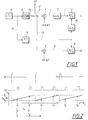
- Fig. 1 a device is shown whose time error is to be determined.
- the method according to the invention means that a special, periodic signal - the test signal - is inputted into the device, the time error of which is to be determined.
- the test signal can for example consist of a periodic frequency sweep.
- the test signal is sampled for every period (frequency sweep) at least twice at different times, and associated samples from a number of periods/cycles (frequency sweeps) are Fourier transformed to create a spectrum which comprises expressions that describe both the fundamental tone of the test signal as well as its image tone, with regard to both amplitude and phase.
- a relation is created from the expressions between the image tone and fundamental tone of the test signal, as an example, the quotient between these expressions.
- the relation is calculated for at least two different sampling time points and from these the time error is calculated.
- the device shown in Fig. 1 comprises two mixers 1 and 2.
- the outputs of the mixers are each connected to two A/D-converters 5 and 6.
- the signal inputs of the mixers are connected to, and normally fed with, an information carrying, carrier modulated signal IF via the connection 3 and switch 4.
- the switch 4 is then in a state that is indicated with a dotted line in Fig. 1.
- a conversion is done in the mixers 1 and 2 with the signals cos( ⁇ 1t) and sin( ⁇ 1t) respectively, which implies that the phase difference between the result from mixer 1 and 2 is 90° and the result becomes a quadrature whose components in Fig. 1 have been referenced with i and q respectively.
- the time error is symbolised in Fig. 1 with a first time delay means 7 with the delay ⁇ t1 that acts on the signal i, and the time delayed signal i is referenced i'.
- the signals are sampled.
- the sampling is done in the A/D-converters 5 and 6.
- Control of the sampling is done with the help of a time controlling means 8 that controls the times for sampling.
- the control consists of a finite sequence of pulses that is repeated at a rate that is determined by a pulse generating means 9.
- the pulse generating means 9 consequently controls the time controlling means 8.
- a special test signal is connected to the mixers 1 and 2 instead of the signal IF. This is done by letting switch 3 adopt the position shown in Fig. 1 whereby a test signal generator 11 is connected to the inputs of the mixers. Test signal generators emit a test signal that consists of a frequency sweep with the slope ⁇ (rad/s). The test signal is syncronized with the control of the sampling in the A/D-converters 5 and 6 because it is controlled from the common pulse generating means 9.
- FIG. 2 An example of a time sequence is shown in the time diagram in Fig. 2.
- the X-axis of the diagram indicates time t and the uppermost sequence shows the time position for the pulses that make up the output signal 12 from the pulse generating means 9.
- the middle sequence shows, in a corresponding way, the pulses that make up the output signal 13 from the time controlling means 8.
- i' and q are sampled two times for every pulse from the pulse generating means 9. The sampling is done at the times t' n and t'' n respectively where n indicates the ordinal of the frequency swept test signal. For every frequency sweep, the times t' n and t' n each occur individually at the same time distance from the beginning of the sweep.
- test signal 14 shows the test signal 14. As has been mentioned earlier, this signal is made up of a frequency sweep. In the shown example the frequency is swept between the frequency values f1 and f2, and the start of the frequency sweep is syncronized with the pulses of the signal 12.
- test signal contains a linear positive frequency sweep which means that the input signal can be written as: e j( ⁇ 2 t p + 1 2 ⁇ t 2 ) where
- the time error ⁇ t can thus be estimated with the help of the unreal parts of k' and k'' and the frequency change of the test signal between the sampling time points.
- the thus measured/calculated time error can for example be fed back to the A/D-converter for controlling a delay function for elimination of the time error.
- test signal with a linearly increasing frequency has been used.
- the method can also be used for other types of test signals.
- it can be a linearly decreasing frequency or a step by step changing frequency between a number of known frequencies whereby the sampling is done at different frequencies.
- the time distance between the sampling occasions should be both adapted to the bandwidth of the subsequent A/D-converter, as well as be chosen so that the frequency change of the test signal between the samples becomes as large as possible, whereby a better signal/noise relationship is attained.
Landscapes
- Physics & Mathematics (AREA)
- Mathematical Physics (AREA)
- Engineering & Computer Science (AREA)
- Theoretical Computer Science (AREA)
- Radar Systems Or Details Thereof (AREA)
- Analogue/Digital Conversion (AREA)
- Testing, Inspecting, Measuring Of Stereoscopic Televisions And Televisions (AREA)
Applications Claiming Priority (2)
| Application Number | Priority Date | Filing Date | Title |
|---|---|---|---|
| SE9402372A SE503070C2 (sv) | 1994-07-05 | 1994-07-05 | Förfarande för bestämning av tidsfel i samband med analog- digitalomvandling av kvadraturdetekterade signaler |
| SE9402372 | 1994-07-05 |
Publications (2)
| Publication Number | Publication Date |
|---|---|
| EP0691748A1 true EP0691748A1 (fr) | 1996-01-10 |
| EP0691748B1 EP0691748B1 (fr) | 2000-10-04 |
Family
ID=20394635
Family Applications (1)
| Application Number | Title | Priority Date | Filing Date |
|---|---|---|---|
| EP95850120A Expired - Lifetime EP0691748B1 (fr) | 1994-07-05 | 1995-06-27 | Méthode pour détecter des erreurs dans une conversion analogue-numérique |
Country Status (4)
| Country | Link |
|---|---|
| US (1) | US5631646A (fr) |
| EP (1) | EP0691748B1 (fr) |
| DE (1) | DE69518999T2 (fr) |
| SE (1) | SE503070C2 (fr) |
Families Citing this family (5)
| Publication number | Priority date | Publication date | Assignee | Title |
|---|---|---|---|---|
| CN1104092C (zh) * | 1997-02-26 | 2003-03-26 | 艾利森电话股份有限公司 | 模拟信号抽样的方法和设备 |
| US7088765B1 (en) * | 2000-03-15 | 2006-08-08 | Ndsu Research Foundation | Vector calibration system |
| US7293476B2 (en) * | 2004-08-20 | 2007-11-13 | Honeywell International Inc. | Power sensor module for engine transmission and driveline applications |
| KR100755681B1 (ko) * | 2006-06-30 | 2007-09-05 | 삼성전자주식회사 | 아날로그 신호를 디지털 신호로 변환하기 위한 장치 및방법 |
| DE102013007903B4 (de) * | 2013-05-07 | 2016-11-10 | Infineon Technologies Ag | Vorrichtung und Verfahren zum Charakterisieren von AD-Wandlern |
Citations (4)
| Publication number | Priority date | Publication date | Assignee | Title |
|---|---|---|---|---|
| US4875049A (en) * | 1984-11-06 | 1989-10-17 | Nec Corporation | Automatic level control circuit for an ad convertor |
| EP0490275A2 (fr) | 1990-12-10 | 1992-06-17 | Hughes Aircraft Company | Système et méthode pour compenser le désquilibre en gain et phase de deux voies en quadrature |
| EP0500507A1 (fr) * | 1991-02-20 | 1992-08-26 | Telefonaktiebolaget L M Ericsson | Méthode pour la réduction de l'influence des produits distordants |
| DE4306880C1 (de) * | 1993-03-05 | 1994-06-16 | Ant Nachrichtentech | QAM-Empfänger mit Schaltungsmitteln zur Korrektur eines Senderquadraturfehlers |
Family Cites Families (4)
| Publication number | Priority date | Publication date | Assignee | Title |
|---|---|---|---|---|
| US3950750A (en) * | 1974-10-03 | 1976-04-13 | Raytheon Company | Radar system having quadrature phase detector compensator |
| US4003054A (en) * | 1974-10-03 | 1977-01-11 | Raytheon Company | Method of compensating for imbalances in a quadrature demodulator |
| US4700222A (en) * | 1985-05-30 | 1987-10-13 | Gill Industries, Incorporated | Apparatus and method of testing the frequency response of a cable television system |
| US5124708A (en) * | 1991-02-25 | 1992-06-23 | The United States Of America As Represented By The Secretary Of The Air Force | RF stability measuring system for MTI radars |
-
1994
- 1994-07-05 SE SE9402372A patent/SE503070C2/sv not_active IP Right Cessation
-
1995
- 1995-06-27 DE DE69518999T patent/DE69518999T2/de not_active Expired - Lifetime
- 1995-06-27 EP EP95850120A patent/EP0691748B1/fr not_active Expired - Lifetime
- 1995-06-30 US US08/497,050 patent/US5631646A/en not_active Expired - Lifetime
Patent Citations (4)
| Publication number | Priority date | Publication date | Assignee | Title |
|---|---|---|---|---|
| US4875049A (en) * | 1984-11-06 | 1989-10-17 | Nec Corporation | Automatic level control circuit for an ad convertor |
| EP0490275A2 (fr) | 1990-12-10 | 1992-06-17 | Hughes Aircraft Company | Système et méthode pour compenser le désquilibre en gain et phase de deux voies en quadrature |
| EP0500507A1 (fr) * | 1991-02-20 | 1992-08-26 | Telefonaktiebolaget L M Ericsson | Méthode pour la réduction de l'influence des produits distordants |
| DE4306880C1 (de) * | 1993-03-05 | 1994-06-16 | Ant Nachrichtentech | QAM-Empfänger mit Schaltungsmitteln zur Korrektur eines Senderquadraturfehlers |
Also Published As
| Publication number | Publication date |
|---|---|
| SE9402372D0 (sv) | 1994-07-05 |
| SE9402372L (sv) | 1996-01-06 |
| DE69518999T2 (de) | 2001-03-29 |
| DE69518999D1 (de) | 2000-11-09 |
| EP0691748B1 (fr) | 2000-10-04 |
| SE503070C2 (sv) | 1996-03-18 |
| US5631646A (en) | 1997-05-20 |
Similar Documents
| Publication | Publication Date | Title |
|---|---|---|
| US6269317B1 (en) | Self-calibration of an oscilloscope using a square-wave test signal | |
| US5369411A (en) | Imbalance correction of in-phase and quadrature phase return signals | |
| JPH0778513B2 (ja) | 高速rf計測用レシーバにおける自己領域設定、直交信号発生、デジタル位相基準発生およびキャリブレーションのための方法および装置 | |
| US6240130B1 (en) | Method and apparatus to measure jitter. | |
| JPS6071966A (ja) | デジタルスペクトルアナライザ | |
| JPH0146835B2 (fr) | ||
| EP0568056B1 (fr) | Dispositif pour la correction d'erreurs de phase de quadrature d'un démodulateur synchrone | |
| JP2002323556A (ja) | 距離計測装置 | |
| EP0691748B1 (fr) | Méthode pour détecter des erreurs dans une conversion analogue-numérique | |
| EP0191478A2 (fr) | Circuit de mesure pour l'évaluation d'un convertisseur numérique-analogique | |
| US4180859A (en) | System for measuring the speed of rotation of a synchro by means of a sampling technique | |
| US6049297A (en) | Digital phase measuring system and method | |
| US20210341524A1 (en) | Timing Difference Detection Circuit Capable of Detecting a Phase Difference Between Different Channels | |
| EP0192981A1 (fr) | Circuit pour mesurer les caractéristiques d'un dispositif à tester | |
| US3548107A (en) | Signal processing apparatus for multiplex transmission | |
| RU2054691C1 (ru) | Способ обработки некогерентного пакета радиоимпульсов | |
| US5188114A (en) | Method and apparatus for elimination of mirroring in signal processing system | |
| US7526701B2 (en) | Method and apparatus for measuring group delay of a device under test | |
| US20020180419A1 (en) | Precision rms measurement | |
| RU2115900C1 (ru) | Устройство для измерения осевого усилия и крутящего момента гребного винта судна | |
| US5585753A (en) | Sawtooth generator and signal interpolating apparatus using the same | |
| US4654585A (en) | Phase detection method | |
| US6529012B1 (en) | Arrangement for determining the complex transmission function of a measuring device | |
| US20040130333A1 (en) | Rf power measurement | |
| US20030233599A1 (en) | Method and apparatus for measuring group delay of a device under test |
Legal Events
| Date | Code | Title | Description |
|---|---|---|---|
| PUAI | Public reference made under article 153(3) epc to a published international application that has entered the european phase |
Free format text: ORIGINAL CODE: 0009012 |
|
| AK | Designated contracting states |
Kind code of ref document: A1 Designated state(s): DE FR GB |
|
| 17P | Request for examination filed |
Effective date: 19960620 |
|
| 17Q | First examination report despatched |
Effective date: 19990222 |
|
| GRAG | Despatch of communication of intention to grant |
Free format text: ORIGINAL CODE: EPIDOS AGRA |
|
| GRAG | Despatch of communication of intention to grant |
Free format text: ORIGINAL CODE: EPIDOS AGRA |
|
| GRAH | Despatch of communication of intention to grant a patent |
Free format text: ORIGINAL CODE: EPIDOS IGRA |
|
| 17Q | First examination report despatched |
Effective date: 19990222 |
|
| GRAH | Despatch of communication of intention to grant a patent |
Free format text: ORIGINAL CODE: EPIDOS IGRA |
|
| GRAA | (expected) grant |
Free format text: ORIGINAL CODE: 0009210 |
|
| AK | Designated contracting states |
Kind code of ref document: B1 Designated state(s): DE FR GB |
|
| REF | Corresponds to: |
Ref document number: 69518999 Country of ref document: DE Date of ref document: 20001109 |
|
| ET | Fr: translation filed | ||
| PLBE | No opposition filed within time limit |
Free format text: ORIGINAL CODE: 0009261 |
|
| STAA | Information on the status of an ep patent application or granted ep patent |
Free format text: STATUS: NO OPPOSITION FILED WITHIN TIME LIMIT |
|
| 26N | No opposition filed | ||
| REG | Reference to a national code |
Ref country code: GB Ref legal event code: IF02 |
|
| PGFP | Annual fee paid to national office [announced via postgrant information from national office to epo] |
Ref country code: GB Payment date: 20140627 Year of fee payment: 20 |
|
| PGFP | Annual fee paid to national office [announced via postgrant information from national office to epo] |
Ref country code: DE Payment date: 20140627 Year of fee payment: 20 |
|
| PGFP | Annual fee paid to national office [announced via postgrant information from national office to epo] |
Ref country code: FR Payment date: 20140617 Year of fee payment: 20 |
|
| REG | Reference to a national code |
Ref country code: DE Ref legal event code: R071 Ref document number: 69518999 Country of ref document: DE |
|
| REG | Reference to a national code |
Ref country code: GB Ref legal event code: PE20 Expiry date: 20150626 |
|
| PG25 | Lapsed in a contracting state [announced via postgrant information from national office to epo] |
Ref country code: GB Free format text: LAPSE BECAUSE OF EXPIRATION OF PROTECTION Effective date: 20150626 |