EP0692207A1 - Regaleaufbau - Google Patents
Regaleaufbau Download PDFInfo
- Publication number
- EP0692207A1 EP0692207A1 EP94305200A EP94305200A EP0692207A1 EP 0692207 A1 EP0692207 A1 EP 0692207A1 EP 94305200 A EP94305200 A EP 94305200A EP 94305200 A EP94305200 A EP 94305200A EP 0692207 A1 EP0692207 A1 EP 0692207A1
- Authority
- EP
- European Patent Office
- Prior art keywords
- stanchion
- cable
- assembly
- shelf
- support means
- Prior art date
- Legal status (The legal status is an assumption and is not a legal conclusion. Google has not performed a legal analysis and makes no representation as to the accuracy of the status listed.)
- Withdrawn
Links
- 239000004411 aluminium Substances 0.000 description 3
- XAGFODPZIPBFFR-UHFFFAOYSA-N aluminium Chemical compound [Al] XAGFODPZIPBFFR-UHFFFAOYSA-N 0.000 description 3
- 229910052782 aluminium Inorganic materials 0.000 description 3
- 239000000463 material Substances 0.000 description 3
- 229910000831 Steel Inorganic materials 0.000 description 2
- 239000004033 plastic Substances 0.000 description 2
- 229920003023 plastic Polymers 0.000 description 2
- 239000010959 steel Substances 0.000 description 2
- 239000007787 solid Substances 0.000 description 1
- 125000006850 spacer group Chemical group 0.000 description 1
- 239000002023 wood Substances 0.000 description 1
Images

Classifications
-
- A—HUMAN NECESSITIES
- A47—FURNITURE; DOMESTIC ARTICLES OR APPLIANCES; COFFEE MILLS; SPICE MILLS; SUCTION CLEANERS IN GENERAL
- A47B—TABLES; DESKS; OFFICE FURNITURE; CABINETS; DRAWERS; GENERAL DETAILS OF FURNITURE
- A47B57/00—Cabinets, racks or shelf units, characterised by features for adjusting shelves or partitions
- A47B57/30—Cabinets, racks or shelf units, characterised by features for adjusting shelves or partitions with means for adjusting the height of detachable shelf supports
- A47B57/48—Cabinets, racks or shelf units, characterised by features for adjusting shelves or partitions with means for adjusting the height of detachable shelf supports consisting of tongues, pins or similar projecting means coacting with openings
- A47B57/485—Straight pins
- A47B57/487—Straight pins with varying cross-section
-
- A—HUMAN NECESSITIES
- A47—FURNITURE; DOMESTIC ARTICLES OR APPLIANCES; COFFEE MILLS; SPICE MILLS; SUCTION CLEANERS IN GENERAL
- A47B—TABLES; DESKS; OFFICE FURNITURE; CABINETS; DRAWERS; GENERAL DETAILS OF FURNITURE
- A47B43/00—Cabinets, racks or shelf units, characterised by features enabling folding of the cabinet or the like
- A47B43/003—Suspended shelves, e.g. by means of supple elements
- A47B43/006—Suspended shelves, e.g. by means of supple elements fixed on cords, cables, wire or chains
Definitions
- This invention relates to shelving.
- the invention is particularly, though not exclusively, applicable to shelving for display purposes in shops as well as for domestic use.
- a particularly attractive shelving arrangement uses cables from which the shelves themselves are suspended.
- the thin cable also presents a minimal obstruction to viewing across shelf supports.
- cable-based shelving is expensive and has to be constructed carefully by experienced fitters.
- a shelving assembly comprising at least one stanchion, a supporting member projecting laterally outwardly from the stanchion toward one end thereof, at least one cable depending from the member, forward shelf support means connected with the cable, rear shelf support means and a shelf suspended from the first and second shelf support means.
- the invention combines the rigidity and simplicity of a rigid rear stanchion with the attractive and unobtrusive cable supporting the shelf toward the front of the display shelf.
- the stanchion itself may be wall mounted.
- the stanchion provides a large surface area by which it may be secured reliably to a wall.
- the stanchion has a foot or other supporting plate so that it could stand on the floor and be self-supporting or even be suspended from a ceiling.
- the shelf is supported on the stanchion by locating means, constituting the rear shelf support means, projecting from one of the stanchion and the shelf into the other.
- the locating means When the cable end, remote from the supporting member, is also secured relative to the stanchion, the locating means have only to resist a shear force as movement of the shelf laterally with respect to the stanchion is substantially prevented by the secured cable.
- the locating means may be a pin dowel or other projection projecting laterally from the stanchion into the shelf. If the pin or dowel projects at an angle to the width of the shelf it also serves to resist lateral front-to-back and side-to-side movement of the shelf relative to the stanchion.
- the arrangement may also have a second cable depending from the member.
- the rear shelf support means may be connected with the second cable.
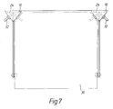
- the stanchion may have a triangular, a rectangular or even a circular or other arcuate section. It may be constructed of wood, suitably rigid plastics material, aluminium (either folded sheet or extruded) or steel.
- the securing means may be releasable for height adjustment.
- the locating pin or dowel may be insertable in one of a series of spaced holes in the stanchion.
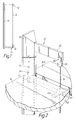
- a shelving arrangement comprises a stanchion 10, which in this embodiment is wall mountable, laterally projecting aluminium upper and lower brackets 12 and 14 and a cable 16 which is suspended from the end of the upper bracket 12 remote from the stanchion 10.
- the cable is also connected with a lower bracket 14 by means of a tensioning screw arrangement 18.
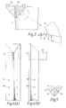
- the upper end of the stanchion is illustrated in more detail in Figures 2 and 4(a) and (b).
- the upper bracket 12 comprises an arm 20 which projects through a slot in the stanchion.
- a fixing plate 22 is connected with the arm. This plate is secured onto the surface of a recess 24 (see Figure 3) in the stanchion 10 by four screws.
- the plate 22 housed within the recess 24.
- the cable 16 is pivotably connected with the arm 20 towards its end remote from the stanchion 10 by a slotted head 26 having a pin 28 which projects through holes in the head and a hole in the arm itself.
- a shelf 30 is supported, at its wall- or stanchion-side by a pin 32 which is located in one of a series of blind holes 34 running along substantially the length of the stanchion 10. It will be noted that the pin projects at an angle to the width of the shelf 30, in this case about 45°, although normally with respect to the surface into which the hole is formed.
- a corner of the shelf 30 is chamfered to accommodate the side of the stanchion from which the pin 28 projects. This shelf rests on the pin 32 in a region of the chamfered corner. The chamfered corner is formed with a recess 36 in its lower surface to take the pin.
- the embodiment illustrated has an end of the shelf 30 connected with the stanchion on one side and a second shelf 30a starting from the other side of the centre of the stanchion.
- a single run of shelving could equally well pass a stanchion and be formed with an appropriately shaped notch to take the stanchion shape and recessed to register with the supporting pins 32.
- the front part of the shelf 30 remote from the stanchion 10 is supported by a support 40 which comprises a circular body 42 of material (possibly steel or a durable plastics material or aluminium) that is formed with a pair of upwardly facing flats 44 on either axial end.
- the shelves 30 and 30a rest on the flats.
- the body 42 also has a vertical bore through which the cable passes.
- the body 42 is held in place by a grub screw 46 which is threadingly engaged in a hole in the body, which hole extends normally relative to the axis of the vertical bore.
- the grub screw 46 is tightened up to bear on the cable 16 passing through the bore.
- the shelf would have to be formed with a hole through which the cable could pass.
- the tension arrangement 18 comprises a slotted bolt 50 which is pivotably secured to the lower bracket 14 by a pin 52 in a similar manner to the head 26 secured to the upper bracket 12.
- An adjuster sleeve 54 is threadingly received on the bolt 50.
- the sleeve 54 has a smaller bore into which is received the lower end of the cable 16.
- Grub screws 56 engage the cable 16 through horizontal holes to hold it in the sleeve.
- the single shelf support 40a has only a single flat formed on one axial end of the drum.
- the means of support for the shelf provided by the pins in the stanchion could be replaced by a second cable suspended between the brackets 12 and 14. If the cables are sufficiently stiff and well tensioned the movement laterally with respect to the stanchion will be substantially prevented.
- a single cable could be passed around a pulley or other point attached to the stanchion 10 above the upper bracket 12 and down through spaced apertures in the bracket and extending in parallel through similarly spaced holes in the lower bracket 14. The ends of the single cable are then attached to a tensioner also attached to the stanchion 10 beneath the lower bracket 14. The cable is thus supported by the pulley and the brackets serve as spacers supporting the cables in their spaced relationship.
- the stanchion can be bolted or otherwise secured to the wall by suitable fixings such as expansion bolts.
- the stanchion provides a secure means of fixing the brackets to a wall.
- the brackets are fixed reliably and securely to the stanchion instead of having to rely on the less certain securement of the plate of the bracket to masonry. Because the stanchion covers a considerably larger area, it is more likely that a solid fixing for the stanchion can be found.
- the stanchion also provides a convenient means of keeping the shelf from moving laterally.
- the rear stanchion is concerned with lateral movement and supporting the rear of the shelf while the first shelf support mounted on the front cable holds up the front of the shelf.
Landscapes
- Assembled Shelves (AREA)
Priority Applications (2)
| Application Number | Priority Date | Filing Date | Title |
|---|---|---|---|
| GB9302563A GB2274974B (en) | 1993-02-10 | 1993-02-10 | Improvements in shelving assemblies |
| EP94305200A EP0692207A1 (de) | 1993-02-10 | 1994-07-15 | Regaleaufbau |
Applications Claiming Priority (2)
| Application Number | Priority Date | Filing Date | Title |
|---|---|---|---|
| GB9302563A GB2274974B (en) | 1993-02-10 | 1993-02-10 | Improvements in shelving assemblies |
| EP94305200A EP0692207A1 (de) | 1993-02-10 | 1994-07-15 | Regaleaufbau |
Publications (1)
| Publication Number | Publication Date |
|---|---|
| EP0692207A1 true EP0692207A1 (de) | 1996-01-17 |
Family
ID=26137189
Family Applications (1)
| Application Number | Title | Priority Date | Filing Date |
|---|---|---|---|
| EP94305200A Withdrawn EP0692207A1 (de) | 1993-02-10 | 1994-07-15 | Regaleaufbau |
Country Status (2)
| Country | Link |
|---|---|
| EP (1) | EP0692207A1 (de) |
| GB (1) | GB2274974B (de) |
Cited By (1)
| Publication number | Priority date | Publication date | Assignee | Title |
|---|---|---|---|---|
| US10441079B2 (en) | 2016-06-10 | 2019-10-15 | Herman Miller, Inc. | Height adjustable stanchion |
Citations (4)
| Publication number | Priority date | Publication date | Assignee | Title |
|---|---|---|---|---|
| EP0004517A2 (de) * | 1978-03-28 | 1979-10-03 | Jean-Marie Beauvais | Handregal aus Borden, die an aus Rohren gebildeten Konsolen aufgehängt sind |
| DE8601127U1 (de) * | 1986-01-16 | 1986-04-10 | Peill + Putzler Glashüttenwerke GmbH, 52349 Düren | Display |
| DE8810286U1 (de) * | 1988-08-12 | 1988-10-06 | Franke, Michael, Dipl.-Kaufm., 8000 München | Vielseitig verwendbare Regaleinrichtung |
| WO1992014382A1 (de) * | 1991-02-14 | 1992-09-03 | Walter K. Baumann Industrietechnik | Freitragendes regal |
-
1993
- 1993-02-10 GB GB9302563A patent/GB2274974B/en not_active Expired - Lifetime
-
1994
- 1994-07-15 EP EP94305200A patent/EP0692207A1/de not_active Withdrawn
Patent Citations (4)
| Publication number | Priority date | Publication date | Assignee | Title |
|---|---|---|---|---|
| EP0004517A2 (de) * | 1978-03-28 | 1979-10-03 | Jean-Marie Beauvais | Handregal aus Borden, die an aus Rohren gebildeten Konsolen aufgehängt sind |
| DE8601127U1 (de) * | 1986-01-16 | 1986-04-10 | Peill + Putzler Glashüttenwerke GmbH, 52349 Düren | Display |
| DE8810286U1 (de) * | 1988-08-12 | 1988-10-06 | Franke, Michael, Dipl.-Kaufm., 8000 München | Vielseitig verwendbare Regaleinrichtung |
| WO1992014382A1 (de) * | 1991-02-14 | 1992-09-03 | Walter K. Baumann Industrietechnik | Freitragendes regal |
Cited By (1)
| Publication number | Priority date | Publication date | Assignee | Title |
|---|---|---|---|---|
| US10441079B2 (en) | 2016-06-10 | 2019-10-15 | Herman Miller, Inc. | Height adjustable stanchion |
Also Published As
| Publication number | Publication date |
|---|---|
| GB2274974A (en) | 1994-08-17 |
| GB2274974B (en) | 1996-10-09 |
| GB9302563D0 (en) | 1993-03-24 |
Similar Documents
| Publication | Publication Date | Title |
|---|---|---|
| US9420886B2 (en) | Television support and mounting kit | |
| US4949929A (en) | Adjustable L-shaped mounting bracket | |
| US11819127B2 (en) | Television support and mounting kit | |
| US5050832A (en) | Modular storage unit mounting system | |
| US4685575A (en) | Wall mounting system for shelves | |
| US6427855B2 (en) | Modular display system | |
| US6609621B2 (en) | Net anchorage methods and apparatus | |
| US5230492A (en) | Support bracket | |
| CA2161753C (en) | Adjustable shelf bracket and standard system | |
| AU752503B2 (en) | Mounting bracket for a camera base | |
| US8038112B2 (en) | Shelf support bracket and wall standard | |
| CA2173568A1 (en) | Cabinet construction system | |
| EP1713356A1 (de) | Hängelagerregal | |
| US7261213B2 (en) | Closet partition system | |
| US20060070967A1 (en) | Overhead attachable storage shelf | |
| EP0692207A1 (de) | Regaleaufbau | |
| KR200283224Y1 (ko) | 케이블트레이 지지용 브래킷 | |
| GB2228185A (en) | Display system | |
| WO2004076758A2 (en) | Auxiliary wall structures | |
| IE890472L (en) | A display system | |
| MXPA01009135A (en) | Wall mounted display fixture system | |
| GB2187084A (en) | Improvements in or relating to adjustable bracket systems | |
| JPH09201245A (ja) | 什器固定用具 | |
| CA2525807A1 (en) | Overhead attachable storage shelf | |
| CA2174024A1 (en) | Adjustable standard system |
Legal Events
| Date | Code | Title | Description |
|---|---|---|---|
| PUAI | Public reference made under article 153(3) epc to a published international application that has entered the european phase |
Free format text: ORIGINAL CODE: 0009012 |
|
| AK | Designated contracting states |
Kind code of ref document: A1 Designated state(s): DE ES FR IT SE |
|
| STAA | Information on the status of an ep patent application or granted ep patent |
Free format text: STATUS: THE APPLICATION IS DEEMED TO BE WITHDRAWN |
|
| 18D | Application deemed to be withdrawn |
Effective date: 19960718 |