EP0692806B1 - Disjoncteur - Google Patents
Disjoncteur Download PDFInfo
- Publication number
- EP0692806B1 EP0692806B1 EP95110421A EP95110421A EP0692806B1 EP 0692806 B1 EP0692806 B1 EP 0692806B1 EP 95110421 A EP95110421 A EP 95110421A EP 95110421 A EP95110421 A EP 95110421A EP 0692806 B1 EP0692806 B1 EP 0692806B1
- Authority
- EP
- European Patent Office
- Prior art keywords
- trip
- circuit breaker
- detent
- armature
- frame
- Prior art date
- Legal status (The legal status is an assumption and is not a legal conclusion. Google has not performed a legal analysis and makes no representation as to the accuracy of the status listed.)
- Expired - Lifetime
Links
- 230000007246 mechanism Effects 0.000 claims description 33
- 239000004020 conductor Substances 0.000 claims description 21
- 230000002159 abnormal effect Effects 0.000 claims description 17
- 230000000712 assembly Effects 0.000 claims 1
- 238000000429 assembly Methods 0.000 claims 1
- 230000000694 effects Effects 0.000 description 3
- 239000002184 metal Substances 0.000 description 3
- 229910052751 metal Inorganic materials 0.000 description 3
- 229910000831 Steel Inorganic materials 0.000 description 2
- 230000008859 change Effects 0.000 description 2
- 230000000717 retained effect Effects 0.000 description 2
- 238000000926 separation method Methods 0.000 description 2
- 239000010959 steel Substances 0.000 description 2
- RYGMFSIKBFXOCR-UHFFFAOYSA-N Copper Chemical compound [Cu] RYGMFSIKBFXOCR-UHFFFAOYSA-N 0.000 description 1
- 230000009471 action Effects 0.000 description 1
- 230000002411 adverse Effects 0.000 description 1
- 230000004888 barrier function Effects 0.000 description 1
- 238000005219 brazing Methods 0.000 description 1
- 239000012141 concentrate Substances 0.000 description 1
- 229910052802 copper Inorganic materials 0.000 description 1
- 239000010949 copper Substances 0.000 description 1
- 238000006073 displacement reaction Methods 0.000 description 1
- 238000010292 electrical insulation Methods 0.000 description 1
- 230000037431 insertion Effects 0.000 description 1
- 238000003780 insertion Methods 0.000 description 1
- 238000003475 lamination Methods 0.000 description 1
- 230000000670 limiting effect Effects 0.000 description 1
- 230000014759 maintenance of location Effects 0.000 description 1
- 238000004519 manufacturing process Methods 0.000 description 1
- 230000036961 partial effect Effects 0.000 description 1
- 238000005192 partition Methods 0.000 description 1
- 230000001681 protective effect Effects 0.000 description 1
- 230000004044 response Effects 0.000 description 1
- 230000000452 restraining effect Effects 0.000 description 1
- 230000035945 sensitivity Effects 0.000 description 1
- 230000035939 shock Effects 0.000 description 1
- 239000007787 solid Substances 0.000 description 1
Images



Classifications
-
- H—ELECTRICITY
- H01—ELECTRIC ELEMENTS
- H01H—ELECTRIC SWITCHES; RELAYS; SELECTORS; EMERGENCY PROTECTIVE DEVICES
- H01H71/00—Details of the protective switches or relays covered by groups H01H73/00 - H01H83/00
- H01H71/74—Means for adjusting the conditions under which the device will function to provide protection
- H01H71/7463—Adjusting only the electromagnetic mechanism
Definitions
- This invention relates to an improved circuit breaker and more particularly to a circuit breaker in which the magnetic trip assembly includes an armature having a nib extending angularly therefrom, the nib having a detent which is engaged by biasing means.
- Circuit breakers provide protection for electrical systems from electrical fault conditions such as current overloads and short circuits.
- circuit breakers include a spring powered operating mechanism which opens electrical contacts to interrupt the current through the conductors on an electrical system in response to abnormal currents.
- the operating mechanism is unlatched by a trip bar which in turn is operated by a trip mechanism associated with each phase of the electrical system.
- the trip mechanism can include a magnetic trip device comprising a fixed magnetic structure energized by the current flowing through the conductor, and a movable armature which is attracted toward the stationary magnetic structure to operate the trip bar.
- the trip bar in turn unlatches the operating mechanism to open the electrical contacts in each phase of the electrical system.
- the movable armature is biased away from the stationary magnetic structure by a spring, called a torsion spring, thereby forming a gap between the armature and the stationary magnetic structure in the absence of an abnormal current.
- circuit breaker that includes a magnetic trip assembly in which the biasing force applied to the movable armature is consistently and accurately controlled and can be calibrated and adjusted.
- a circuit breaker for responding to abnormal currents in a conductor in an electrical system comprising:
- a circuit breaker for responding to abnormal currents in conductors associated with each phase in a multiphase electrical system comprising:
- the improved circuit breaker of the invention has met the above need as well as others.
- the circuit breaker comprises electrical contacts operable between a closed position in which a circuit is completed through the conductor and an open position in which the circuit through the conductor is interrupted, a latchable operating mechanism operable to open the electrical contacts when unlatched and a trip bar rotatable from a biased position to a trip position to unlatch the operating mechanism.
- the circuit breaker further comprises a magnetic trip assembly including a frame, a stationary magnetic structure mounted to the frame and a movable armature which is attracted to the stationary magnetic structure by abnormal current through the conductor to rotate the trip bar to a trip position.
- the movable armature includes a nib extending angularly therefrom, the nib defining a detent.
- Pivot means are provided that pivotably mount the movable armature for rotation about a pivot axis.
- the magnetic trip assembly further comprises biasing means supported by the frame and engaging into the detent to bias the armature away from the stationary magnetic structure to form a gap therebetween. The biasing means disengages from the detent when the armature is attracted to the stationary magnetic structure by the abnormal current through the conductor to allow the movable armature to rotate about the pivot axis and trip the trip bar to interrupt the circuit.
- Figure 1 is a top plan view of a circuit breaker incorporating the invention.
- Figure 2 is a side elevation view of the circuit breaker of Figure 1.
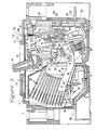
- Figure 3 is an enlarged vertical section through the circuit breaker of Figure 1 taken along the line 3-3 in Figure 1 and illustrating the circuit breaker in the closed position.
- Figure 4 is a detailed vertical sectional view of the magnetic trip assembly in the normal (non-tripped) position showing the nib of the armature extending at an angle of greater than 90° from the armature.
- Figure 5 is a detailed vertical sectional view of the magnetic trip assembly shown in Figure 4 in the tripped position.
- Figure 6 is a detailed vertical sectional view similar to Figure 4 only showing the nib of the armature extending at an angle of less than 90° from the armature, with the armature being in the normal (non-tripped) position.
- Figure 7 is detailed vertical sectional view of the magnetic trip assembly shown in Figure 6 with the armature being in the tripped position.
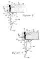
- Figure 8 is a partial top plan view showing the adjustment bar.
- a molded case circuit breaker 1 incorporating a magnetic trip assembly with the improved means of controlling and calibrating the trip set point in accordance with the invention.
- circuit breaker 1 is depicted and described herein as a three-phase, or three-pole circuit breaker, the principles of the invention are equally applicable to single phase or polyphase circuit breakers, and to both ac and dc circuit breakers.
- the circuit breaker 1 includes a molded, electrically insulating, top cover 3 mechanically secured to a molded, electrically insulating, bottom cover or base 5 by fasteners 7.
- a set of first electrical terminals, or line terminals 9a, 9b and 9c are provided, one for each pole or phase.
- a set of second electrical terminals, or load terminals 11a, 11b and 11c are provided at the other end of the circuit breaker base 5. These terminals are used to serially electrically connect circuit breaker 1 into a three-phase electrical circuit for protecting a three-phase electrical system.
- the circuit breaker 1 further includes an electrically insulating, rigid, manually engaging handle 13 extending through an opening 15 in the top cover 3 for setting the circuit breaker 1 to its closed position or its open position.
- the circuit breaker 1 may also assume a tripped position.
- circuit breaker 1 may be reset from the tripped position to the closed position for further protective operation by moving the handle 13 through the open position.
- the handle 13 may be moved either manually or automatically by an operating mechanism 21 ( Figure 3) to be described in more detail.
- an electrically insulating strip 17 ( Figure 3) movable with the handle 13, covers the bottom of the opening 15, and serves as an electrical barrier between the interior and the exterior of the circuit breaker 1.
- the circuit breaker 1 includes a set of electrical contacts 19 for each phase, an operating mechanism 21 and a trip mechanism 23.
- Each set of electrical contacts includes a lower electrical contact 25 and an upper electrical contact 27.
- Associated with each set of electrical contacts 19 are an arc chute 29 and a slot motor 31 both of which are conventional.
- the arc chute 29 divides a single electrical arc formed between separating electrical contacts 25 and 27 upon a fault condition into a series of electrical arcs, increasing the total arc voltage and resulting in a limiting of the magnitude of the fault current.
- the slot motor 31 consisting of either of a series of generally U-shaped steel lamination encased in electrical insulation or of a generally U-shaped electrically insulated, solid steel bar, is disposed about the contacts 25, 27, to concentrate the magnetic field generated upon a high level short circuit or fault current condition thereby greatly increasing the magnetic repulsion forces between the separating electrical contacts 25 and 27 to rapidly accelerate their separation.
- the rapid separation of the electrical contacts 25 and 27 results in a relatively high arc resistance to limit the magnitude of the fault current.
- a more detailed description of the arc chute 29 and slot motor 31 can be found in United States Patent No. 3,815,059, which is expressly incorporated by reference herein.
- the lower electrical contact 25 includes a U-shaped stationary member 33 secured to the base 5 by a fastener 35, a contact 37 for physically and electrically contacting the upper electrical contact 27 and an electrically insulating strip 39 to reduce the possibility of arcing between the upper electrical contact 27 and portions of the lower electrical contact 25.
- the line terminal 9b extending exteriorly of the base 5 comprises an integral end portion of the member 33.
- the upper electrical contact 27 includes a rotatable contact arm 41 and a contact 43 for physically and electrically contacting the lower electrical contact 25.
- the operating mechanism 21 includes an over-center toggle mechanism 47, an integral one-piece molded cross bar 49, a pair of rigid, spaced apart, metal side plates 51, a rigid, pivotable metal handle yoke 53, a rigid stop pin 55, a pair of operating tension springs 57 and a latching mechanism 59.
- the over-center toggle mechanism 47 includes a rigid, metal cradle 61 that is rotatable about the longitudinal central axis of a cradle support pin 63 journalled in the side plates 51.
- the toggle mechanism 47 further includes a pair of upper toggle links 65, a pair of lower toggle links 67, a toggle spring pin 69 and an upper toggle link follower pin 71.
- the lower toggle links 67 are secured to either side of the rotatable contact arm 41 of the upper electrical contact 27 by toggle contact pin 73.
- the ends of the pin 73 are received and retained in the molded cross bar 49.
- movement of the upper electrical contact 27, and the corresponding movement of the cross bar 49 are effected by movement of the lower toggle links 67.
- movement of the upper electrical contact 27 by the operating mechanism 21 in the center pole or phase of the circuit breaker 1 simultaneously, through the rigid cross bar 49 causes the same movement in the electrical contacts 27 associated with the other poles or phases of the circuit breaker 1.
- the upper toggle links 65 and lower toggle links 67 are pivotably connected by the toggle spring pins 69.
- the operating tension springs 57 are stretched between the toggle spring pin 69 and the handle yoke 53 such that the springs 57 remain under tension, enabling the operating of the over-center toggle mechanism 47 to be controlled by and be respective to external movement of the handle 13.
- the upper links 65 also include recesses or grooves 77 for receipt and retention of pin 71.
- Pin 71 passes through the cradle 61 at a location spaced by a predetermined distance from the axis of rotation of the cradle 61.
- Spring tension from the springs 57 retains the pin 71 in engagement with the upper toggle links 65.
- rotational movement of the cradle 61 effects a corresponding movement or displacement of the upper portions of the links 65.
- the cradle 61 has a slot or groove 79 defining a flat latch surface which is configured to engage a flat cradle latch surface formed in the upper end of an elongated slot or aperture 81 in a generally flat intermediate latch plate 83.
- the cradle 61 also includes a generally flat handle yoke contacting surface 85 configured to contact a downwardly depending, elongated surface 87 formed on the upper end of the handle yoke 53.
- the operating springs 57 move the handle 13 during a trip operation and the surfaces 85 and 87 locate the handle 13 in the tripped position intermediate the closed position and the open position of the handle 13, to indicate that the circuit breaker 1 has tripped.
- the engagement of the surfaces 85 and 87 resets the operating mechanism 21 subsequent to a trip operation by moving the cradle 61 in a clockwise direction against the bias of the operating springs 57 from its tripped position to and past its open position to enable the relatching of the latching surfaces on groove 79 and in aperture 81.
- the trip mechanism 23 includes the intermediate latch plate 83, a molded one-piece trip bar 89, a cradle latch plate 91, a torsion spring support pin 93, a double acting torsion spring 95, a magnetic trip assembly 97 and a thermal trip device 99 in the form of a bimetal.
- the molded one-piece trip bar 89 is journalled in vertical partitions (not shown) in the base 5 of the molded case circuit breaker 1 which separate three poles of the circuit breaker.
- the trip bar 89 has actuating levers 103 for each pole extending radially downward.
- a trip lever 105 extending outwardly from the trip bar is engaged by the cradle latch plate 91.
- Cradle latch plate 91 is mounted for rotation about an axis parallel to the trip bar.
- One arm of the double acting torsion spring 95 biases the cradle latch plate 91 against the intermediate latch plate 81.
- the other arm of the torsion spring 95 bears against a vertical projection 107 on the trip bar 89 to bias the trip bar in the counter clockwise direction as viewed in Figure 3.
- a current bearing conductive path between the lower end of the bimetal 99 and the upper electrical contact 27 is achieved by a flexible copper shunt CS connected by any suitable means, for example by brazing to the lower end of the bimetal 99 and to the upper electrical contact 27 within the cross bar 49.
- a flexible copper shunt CS connected by any suitable means, for example by brazing to the lower end of the bimetal 99 and to the upper electrical contact 27 within the cross bar 49.
- the magnetic trip assembly 97 includes an adjustment bar 108, a stationary magnetic structure 109, a frame 110 to which the stationary magnetic structure 109 is mounted, a movable armature 111 and biasing means 112 which will be described in detail below with respect to Figures 4-7.
- the armature 111 includes a nib 113 extending angularly therefrom, the nib defining a detent 114. The remaining portion of the armature 111 is bent along a horizontal axis and slotted at 115 for receipt of a pin 117 about which the armature is pivotably mounted for rotation about a pivot axis P.
- the biasing means 112 is disposed in an accessed through access hole 120 in the adjustment bar 108.
- Figure 4 shows the so-called non-trip position wherein a gap G is formed between the armature 111 and the stationary magnetic structure 109.
- the biasing means 112 consists of a plunger 121 having a first portion 122 disposed in the access hole 120 defined by the adjustment bar 108 and a second portion 123 which projects from the adjustment bar 108 to engage into the detent 114 defined by the nib 113 of the armature 111.
- the first portion 122 of the plunger 121 is retained in the adjustment bar 108 by means of an integral annular retaining lip 124.
- a non-metallic set screw 125 is threadedly engaged in the access hole 120 and is adapted to be moved up and down in the access hole.
- the set screw 125 has an upper portion 126 which defines a channel 127 that can be engaged by a screwdriver or other rotating tool (not shown) to move the set screw 125 up or down in the access hole 120.
- a spring 128 is disposed between the plunger 121 and the set screw 125.
- the threads 135 on the set screw are very fine to obtain an increase in the sensitivity of the calibration. Additionally, the fit on the threads between the set screw threads 135 and the access hole threads 136 are very tight in order to resist any movement of the set screw 125 therein due to vibration or shock of the circuit breaker 1.
- the spring 128 has a spring constant that determines the amount of force that the plunger 121 exerts into the detent 114. It will be appreciated that different springs, with different spring constants can be used in order to vary the force applied by the spring to the plunger 121 and ultimately into the detent 114.
- the portion of the plunger 121 that engages the detent 119, and the detent 114 itself can have different shapes, slopes and dimensions so as to adjust the engagement of one to the other. This, like the spring constant, can effect the amount of force applied between the detent 114 and the plunger 121.
- the nib 113a extends at an angle less than 90° from the remainder of the armature 111a. Not only does this decrease the amount of force necessary to lift plunger 121 from detent 114a, it also means that the armature 111a does not automatically reset after being attracted to the stationary magnetic structure 109, and after the current is interrupted and the magnetic field collapses.
- the plunger 121 may not contact, but in some instances may contact, the nib 113a once the armature 111a is attracted to the stationary magnetic structure 109.
- the compressed spring adds to the magnetic force when out of the detent 113. This assists in the force needed to have the armature 111 move towards the stationary magnetic structure 109 when an abnormal current is present. Because of this, there is no "snap action" to draw the armature 111a back to the set position as shown in Figure 6. In this case, the armature must be reset manually by the user using a special tool that can allow the user access to the armature 111a through the molded circuit breaker case.
- the adjustment bar 108 allows the three poles of the breaker to be adjusted simultaneously as opposed to calibration where each of the poles is set individually. Typically, the current trip point is adjusted between 5x and 10x.
- the adjustment of the adjustment bar 108 is accomplished by rotatable camming mechanism 149 ( Figure 1) which is mounted to the circuit breaker and which is accessible through the cover 3 to provide means for adjusting the position of the adjustment bar 108 without removing the cover 5. Details of the operation of the adjustment bar 108 are found in United States Patent No. 4,958,136, which is hereby incorporated by reference herein.
- Rotation of the camming device 149 by insertion of a tool such as a screwdriver into slot 151 provides the capability of rectilinearly moving the adjustment bar 108 longitudinally.
- the plunger 121 of biasing means 112, along with the plungers (not shown) of biasing means 155 and 156 associated with the other poles of the circuit breaker 1, are moved simultaneously when the camming device 149 is rotated. Since the plungers engage into the detents, the plungers will follow a path defined by the detents.
- the detents 114, 157 and 158 are skewed from the axis A of the rectilinear motion of the adjustment bar 108 and the axis of the trip bar 89 (see Figure 3), axis A and the axis of the trip bar 89 being generally parallel.
- moving the plungers along the detent 114, 157, 158 causes the air gap G (see Figure 4) to change size.
- This in turn causes the magnetic force on the armature to change for a given current.
- changing the skewing of the detents relative to the axis of rectilinear motion of the adjustment bar 108 will alter the range of the gaps G between the armature 111 and the stationary magnetic structure 109.
- circuit breaker which provides protection for electrical systems from electrical fault conditions such as current overloads and short circuits.
Landscapes
- Physics & Mathematics (AREA)
- Electromagnetism (AREA)
- Breakers (AREA)
Claims (10)
- Disjoncteur (1) pour réagir à des courants anormaux dans le conducteur d'une installation électrique, ledit disjoncteur comprenant :des contacts électriques (19) manoeuvrables entre une position de fermeture où un circuit est établit au travers dudit conducteur, et une position d'ouverture où ledit circuit composé dudit conducteur est interrompu ;un mécanisme de commande verrouillable (21) manoeuvrable pour ouvrir lesdits contacts électriques une fois déverrouillé ;une barrette de déclenchement (89) pouvant tourner d'une position de précontrainte à une position de déclenchement pour déverrouiller ledit mécanisme de commande ; etun ensemble de déclenchement magnétique (97) comprenant :un cadre (110);une structure magnétique fixe (109) montée sur ledit cadre ;une armature mobile (111) qui est attirée vers ladite structure magnétique fixe par ledit courant anormal dans ledit conducteur pour faire tourner ladite barrette de déclenchement sur une position de déclenchement, ladite armature mobile comprenant une patte (113) la prolongeant en formant un angle, ladite patte définissant un cran (114) ;un moyen de pivot (117) fixant ladite armature mobile en permettant sa rotation sur un axe de pivotement ; etun moyen de précontrainte (112) monté sur ledit cadre et s'engageant dans ledit cran afin d'écarter ladite armature de ladite structure magnétique fixe pour créer un entrefer (G) entre elles, ledit moyen de précontrainte se dégageant dudit cran lorsque ladite armature est attirée vers ladite structure magnétique fixe par ledit courant anormal dans ledit conducteur afin de permettre la rotation de ladite armature mobile sur ledit axe de pivotement et la libération de ladite barrette de déclenchement pour interrompre ledit circuit.
- Disjoncteur selon la revendication 1, caractérisé en ceque ladite patte prolonge ladite armature sous un angle supérieur à 90° de sorte que, une fois ledit disjoncteur déclenché, ledit moyen de précontrainte écarte ladite armature de ladite structure magnétique fixe et se rengage dans ledit cran.
- Disjoncteur selon la revendication 1, caractérisé en ceque ladite patte prolonge ladite armature sous un angle inférieur à environ 90° de sorte que, une fois ledit disjoncteur déclenché, ladite armature doit être éloignée manuellement de ladite structure magnétique fixe pour rengager ledit moyen de précontrainte dans ledit cran.
- Disjoncteur selon la revendication 1, caractérisé en ceque ledit moyen de précontrainte comprend (i) un poussoir (121) ayant une première partie (122) disposée dans ledit cadre et une seconde partie (123) dépassant dudit cadre pour s'engager dans ledit cran ; (ii) une vis de réglage (125) disposée dans ledit cadre et (iii) un ressort (128) disposé entre ledit poussoir et ladite vis de réglage, dans lequel l'amplitude de la force exercée par ledit poussoir sur ledit cran peut être contrôlée par réglage de ladite vis de réglage, de sorte que ledit disjoncteur peut être calibré pour un seuil de déclenchement désiré.
- Disjoncteur selon la revendication 1, caractérisé en ceque ledit cran a la forme d'une gouttière traversant ladite patte, ladite gouttière ayant une orientation oblique par rapport audit axe de pivotement, où le mouvement rectiligne dudit poussoir, généralement parallèle audit axe de pivotement, assure le réglage dudit entrefer.
- Disjoncteur selon la revendication 1, comprenant un boítier moulé (3, 5) dans lequel sont logés lesdits contacts électriques, mécanisme de commande verrouillable, barrette de déclenchement et ensemble de déclenchement magnétique, de sorte que l'accès audit moyen de précontrainte est impossible sans ouvrir ledit boítier moulé.
- Disjoncteur (1) pour réagir à des courants anormaux dans des conducteurs associés à chaque phase d'une installation polyphasée comprenant :un jeux de contacts électriques (19) pour chaque phase de ladite installation polyphasée établissant un circuit électrique par un conducteur associé en position fermé et interrompant ledit circuit électrique en position ouvert ;un mécanisme de commande verrouillable (21) manoeuvrable pour ouvrir tous les jeux desdits contacts électriques une fois déverrouillé ;une barrette de déclenchement (89) pouvant tourner d'une position de précontrainte à une position de déclenchement pour déverrouiller ledit mécanisme de commande ;un ensemble de déclenchement magnétique (97) pour chaque phase de ladite installation électrique polyphasée, chaque ensemble de déclenchement magnétique comprenant :un cadre (110);une structure magnétique fixe (109) fixée sur ledit cadre ;une armature mobile (111) qui est attirée vers ladite structure magnétique fixe par ledit courant anormal dans ledit conducteur pour faire tourner ladite barrette de déclenchement sur une position de déclenchement, ladite armature mobile comprenant une patte (113) la prolongeant en formant un angle, ladite patte définissant un cran (114) ;un moyen de pivot (117) fixant ladite armature mobile en permettant sa rotation autour d'un axe de pivotement; etun moyen de précontrainte (112) monté sur ledit cadre et s'engageant dans ledit cran afin d'écarter ladite armature mobile de ladite structure magnétique fixe pour créer un entrefer (G) entre elles, ledit moyen de précontrainte se dégageant dudit cran quand ladite armature mobile est attirée vers ladite structure magnétique fixe par ledit courant anormal dans ledit conducteur ;ledit cran a la forme d'une gouttière traversant ladite patte, ladite gouttière ayant une orientation oblique par rapport audit axe de pivotement ; etun moyen de barre de réglage (108) fixé sur au moins un desdits cadres pour déplacer simultanément ledit moyen de précontrainte de manière rectiligne et généralement parallèle audit axe de pivotement, ledit entrefer entre chaque dite armature et chaque dite structure magnétique fixe étant de ce fait réglé simultanément.
- Disjoncteur selon la revendication 7, caractérisé en ceque lesdits axes de pivotement desdites armatures sont alignés axialement ; etledit moyen de réglage est une barre de réglage pouvant effectuer un glissement rectiligne dans une direction généralement parallèle auxdits axes de pivotement desdites armatures pour régler simultanément la précontrainte exercée sur toutes lesdites armatures par ledit moyen de précontrainte entre des réglages de déclenchement haut et bas.
- Disjoncteur selon la revendication 8, comprenant un boítier moulé (3, 5) dans lequel sont logés lesdits jeux de contacts électriques, mécanisme de commande, barrette de déclenchement, ensembles de déclenchement magnétique et moyen de réglage ; etun moyen de réglage de plage rotatif (149) connecté de manière à convertir sa rotation en ledit glissement rectiligne de ladite barre de réglage, ledit moyen de réglage de plage rotatif étant accessible à travers ledit boítier moulé de sorte que lesdites armatures peuvent être mises en précontrainte sur ladite plage entre lesdits réglages haut et bas sans ouvrir ledit boítier moulé.
- Disjoncteur selon la revendication 7, caractérisé en ceque ledit moyen de précontrainte comprend (i) un poussoir (121) ayant une première partie (122) disposée dans ledit cadre et une seconde partie (123) dépassant dudit cadre pour s'engager dans ledit cran ; (ii) une vis de réglage (125) disposée dans ledit cadre et (iii) un ressort (128) disposé entre ledit poussoir et ladite vis de réglage, où l'amplitude de la force exercée par ledit poussoir sur chaque cran peut être contrôlée par réglage de chaque vis de réglage, de sorte que chaque disjoncteur peut être calibré pour un seuil désiré.
Applications Claiming Priority (2)
| Application Number | Priority Date | Filing Date | Title |
|---|---|---|---|
| US274320 | 1994-07-13 | ||
| US08/274,320 US5471184A (en) | 1994-07-13 | 1994-07-13 | Circuit breaker |
Publications (2)
| Publication Number | Publication Date |
|---|---|
| EP0692806A1 EP0692806A1 (fr) | 1996-01-17 |
| EP0692806B1 true EP0692806B1 (fr) | 1998-10-07 |
Family
ID=23047709
Family Applications (1)
| Application Number | Title | Priority Date | Filing Date |
|---|---|---|---|
| EP95110421A Expired - Lifetime EP0692806B1 (fr) | 1994-07-13 | 1995-07-04 | Disjoncteur |
Country Status (5)
| Country | Link |
|---|---|
| US (1) | US5471184A (fr) |
| EP (1) | EP0692806B1 (fr) |
| JP (1) | JPH0855555A (fr) |
| CA (1) | CA2153755A1 (fr) |
| DE (1) | DE69505201T2 (fr) |
Families Citing this family (12)
| Publication number | Priority date | Publication date | Assignee | Title |
|---|---|---|---|---|
| US5705968A (en) * | 1996-05-14 | 1998-01-06 | Eaton Corporation | Trip bar with adjustable latch load for electrical switching apparatus |
| US5927484A (en) * | 1997-05-28 | 1999-07-27 | Eaton Corporation | Circuit breaker with welded contact interlock, gas sealing cam rider and double rate spring |
| US5927482A (en) * | 1998-07-21 | 1999-07-27 | Eaton Corporation | Insulative cover for electrical switching apparatus for electric power distribution systems |
| AU782924B2 (en) * | 2001-09-24 | 2005-09-08 | Moeller Gebaudeautomation Kg | Switching mechanism for a circuit breaker |
| SG98037A1 (en) * | 2001-09-27 | 2003-08-20 | Moeller Gebaudeautomation Kg | Switching mechanism for a circuit breaker |
| KR100425190B1 (ko) * | 2001-12-05 | 2004-03-30 | 엘지산전 주식회사 | 배선용 차단기의 부족전압 트립장치 |
| KR100492254B1 (ko) * | 2003-08-29 | 2005-05-27 | 엘에스산전 주식회사 | 회로 차단기 |
| US6788174B1 (en) | 2004-02-03 | 2004-09-07 | Eaton Corporation | Adjustable magnetic trip unit and a circuit breaker incorporating the same |
| US7186933B2 (en) * | 2005-05-12 | 2007-03-06 | Eaton Corporation | Handle attachment, assist mechanism therefor, and electrical switching apparatus employing the same |
| US7358838B2 (en) * | 2006-02-24 | 2008-04-15 | Eaton Corporation | Electrical switching apparatus and trip indicator therefor |
| CN102360995B (zh) * | 2011-10-25 | 2012-10-10 | 常熟开关制造有限公司(原常熟开关厂) | 断路器的磁脱扣器 |
| KR101537681B1 (ko) * | 2014-01-27 | 2015-07-17 | 엘에스산전 주식회사 | 차단기 |
Family Cites Families (9)
| Publication number | Priority date | Publication date | Assignee | Title |
|---|---|---|---|---|
| US2902560A (en) * | 1955-05-18 | 1959-09-01 | Square D Co | Circuit breaker |
| US3815059A (en) * | 1972-12-01 | 1974-06-04 | Westinghouse Electric Corp | Circuit interrupter comprising electromagnetic opening means |
| FR2446009A1 (fr) * | 1979-01-04 | 1980-08-01 | Alsthom Unelec Sa | Declencheur electromagnetique reglable pour disjoncteur |
| US4630019A (en) * | 1984-09-28 | 1986-12-16 | Westinghouse Electric Corp. | Molded case circuit breaker with calibration adjusting means for a bimetal |
| US4616199A (en) * | 1984-12-21 | 1986-10-07 | Square D Company | Circuit breaker improvement to prevent setting of trip assembly |
| US4639701A (en) * | 1985-08-30 | 1987-01-27 | Westinghouse Electric Corp. | Circuit breaker with interface flux shunt trip |
| US4958136A (en) * | 1989-03-08 | 1990-09-18 | Westinghouse Electric Corp. | Circuit breaker with individual gap adjustment at high and low settings of magnetic trip |
| US4983939A (en) * | 1989-10-05 | 1991-01-08 | Westinghouse Electric Corp. | Circuit breaker with adjustable low magnetic trip |
| US5250918A (en) * | 1992-05-05 | 1993-10-05 | Square D Company | Automatic miniature circuit breaker with Z-axis assemblage current response mechanism |
-
1994
- 1994-07-13 US US08/274,320 patent/US5471184A/en not_active Expired - Fee Related
-
1995
- 1995-07-04 EP EP95110421A patent/EP0692806B1/fr not_active Expired - Lifetime
- 1995-07-04 DE DE69505201T patent/DE69505201T2/de not_active Expired - Fee Related
- 1995-07-12 CA CA002153755A patent/CA2153755A1/fr not_active Abandoned
- 1995-07-13 JP JP7201333A patent/JPH0855555A/ja active Pending
Also Published As
| Publication number | Publication date |
|---|---|
| DE69505201D1 (de) | 1998-11-12 |
| DE69505201T2 (de) | 1999-06-02 |
| US5471184A (en) | 1995-11-28 |
| CA2153755A1 (fr) | 1996-01-14 |
| EP0692806A1 (fr) | 1996-01-17 |
| JPH0855555A (ja) | 1996-02-27 |
Similar Documents
| Publication | Publication Date | Title |
|---|---|---|
| EP0425103B1 (fr) | Disjoncteur avec déclencheur magnétique ajustable à courant faible | |
| US4691182A (en) | Circuit breaker with adjustable magnetic trip unit | |
| US4958136A (en) | Circuit breaker with individual gap adjustment at high and low settings of magnetic trip | |
| US4698606A (en) | Circuit breaker with adjustable thermal trip unit | |
| EP0176869B1 (fr) | Disjoncteur à boîtier moulé avec un moyen d'échappement pour le gaz d'arc | |
| EP0421691B1 (fr) | Disjoncteur avec noyau magnétique mobile pour déclenchement magnétique à courant bas | |
| EP0146033A2 (fr) | Disjoncteur avec mécanisme d'actionnement | |
| US4654490A (en) | Reverse loop circuit breaker with high impedance stationary conductor | |
| US5471184A (en) | Circuit breaker | |
| EP0145990A2 (fr) | Disjoncteur avec assemblage d'une traverse et d'un contact | |
| US4950848A (en) | Adjustable circuit breaker with draw out interlock | |
| EP0276074B1 (fr) | Disjoncteur à circuit magnétique shunt de rappel | |
| US20040227598A1 (en) | Phase-to-phase isolation of cassette type circuit breakers | |
| US3821607A (en) | Circuit interrupter protective device | |
| EP0148746B1 (fr) | Disjoncteur avec déclencheur à manque de tension | |
| US3944959A (en) | Electrical circuit breaker | |
| US5394126A (en) | Circuit breaker with improved magnetic trip assembly | |
| WO2002031849A1 (fr) | Disjoncteur avec derivation pour reacheminer un courant transitoire eleve, et procede associe | |
| AU2002212566A1 (en) | Circuit breaker with bypass for redirecting high transient current and associated method | |
| GB2221346A (en) | Circuit breaker trip bar bearing |
Legal Events
| Date | Code | Title | Description |
|---|---|---|---|
| PUAI | Public reference made under article 153(3) epc to a published international application that has entered the european phase |
Free format text: ORIGINAL CODE: 0009012 |
|
| AK | Designated contracting states |
Kind code of ref document: A1 Designated state(s): DE FR GB IT |
|
| 17P | Request for examination filed |
Effective date: 19960717 |
|
| GRAG | Despatch of communication of intention to grant |
Free format text: ORIGINAL CODE: EPIDOS AGRA |
|
| 17Q | First examination report despatched |
Effective date: 19970919 |
|
| GRAG | Despatch of communication of intention to grant |
Free format text: ORIGINAL CODE: EPIDOS AGRA |
|
| GRAH | Despatch of communication of intention to grant a patent |
Free format text: ORIGINAL CODE: EPIDOS IGRA |
|
| GRAH | Despatch of communication of intention to grant a patent |
Free format text: ORIGINAL CODE: EPIDOS IGRA |
|
| GRAA | (expected) grant |
Free format text: ORIGINAL CODE: 0009210 |
|
| AK | Designated contracting states |
Kind code of ref document: B1 Designated state(s): DE FR GB IT |
|
| PG25 | Lapsed in a contracting state [announced via postgrant information from national office to epo] |
Ref country code: FR Free format text: THE PATENT HAS BEEN ANNULLED BY A DECISION OF A NATIONAL AUTHORITY Effective date: 19981007 |
|
| REF | Corresponds to: |
Ref document number: 69505201 Country of ref document: DE Date of ref document: 19981112 |
|
| ET | Fr: translation filed | ||
| PG25 | Lapsed in a contracting state [announced via postgrant information from national office to epo] |
Ref country code: GB Free format text: LAPSE BECAUSE OF NON-PAYMENT OF DUE FEES Effective date: 19990704 |
|
| PLBE | No opposition filed within time limit |
Free format text: ORIGINAL CODE: 0009261 |
|
| STAA | Information on the status of an ep patent application or granted ep patent |
Free format text: STATUS: NO OPPOSITION FILED WITHIN TIME LIMIT |
|
| 26N | No opposition filed | ||
| GBPC | Gb: european patent ceased through non-payment of renewal fee |
Effective date: 19990704 |
|
| PG25 | Lapsed in a contracting state [announced via postgrant information from national office to epo] |
Ref country code: DE Free format text: LAPSE BECAUSE OF NON-PAYMENT OF DUE FEES Effective date: 20000503 |
|
| REG | Reference to a national code |
Ref country code: FR Ref legal event code: ST |
|
| PG25 | Lapsed in a contracting state [announced via postgrant information from national office to epo] |
Ref country code: IT Free format text: LAPSE BECAUSE OF NON-PAYMENT OF DUE FEES;WARNING: LAPSES OF ITALIAN PATENTS WITH EFFECTIVE DATE BEFORE 2007 MAY HAVE OCCURRED AT ANY TIME BEFORE 2007. THE CORRECT EFFECTIVE DATE MAY BE DIFFERENT FROM THE ONE RECORDED. Effective date: 20050704 |