EP0692945B1 - Küchenmaschine mit gesichertem, drehbarem behälter - Google Patents
Küchenmaschine mit gesichertem, drehbarem behälter Download PDFInfo
- Publication number
- EP0692945B1 EP0692945B1 EP95905738A EP95905738A EP0692945B1 EP 0692945 B1 EP0692945 B1 EP 0692945B1 EP 95905738 A EP95905738 A EP 95905738A EP 95905738 A EP95905738 A EP 95905738A EP 0692945 B1 EP0692945 B1 EP 0692945B1
- Authority
- EP
- European Patent Office
- Prior art keywords
- transverse arm
- bowl
- locking mechanism
- kitchen machine
- housing
- Prior art date
- Legal status (The legal status is an assumption and is not a legal conclusion. Google has not performed a legal analysis and makes no representation as to the accuracy of the status listed.)
- Expired - Lifetime
Links
Images


Classifications
-
- A—HUMAN NECESSITIES
- A47—FURNITURE; DOMESTIC ARTICLES OR APPLIANCES; COFFEE MILLS; SPICE MILLS; SUCTION CLEANERS IN GENERAL
- A47J—KITCHEN EQUIPMENT; COFFEE MILLS; SPICE MILLS; APPARATUS FOR MAKING BEVERAGES
- A47J43/00—Implements for preparing or holding food, not provided for in other groups of this subclass
- A47J43/04—Machines for domestic use not covered elsewhere, e.g. for grinding, mixing, stirring, kneading, emulsifying, whipping or beating foodstuffs, e.g. power-driven
- A47J43/07—Parts or details, e.g. mixing tools, whipping tools
- A47J43/08—Driving mechanisms
- A47J43/085—Driving mechanisms for machines with tools driven from the lower side
-
- B—PERFORMING OPERATIONS; TRANSPORTING
- B01—PHYSICAL OR CHEMICAL PROCESSES OR APPARATUS IN GENERAL
- B01F—MIXING, e.g. DISSOLVING, EMULSIFYING OR DISPERSING
- B01F27/00—Mixers with rotary stirring devices in fixed receptacles; Kneaders
- B01F27/05—Stirrers
- B01F27/11—Stirrers characterised by the configuration of the stirrers
- B01F27/114—Helically shaped stirrers, i.e. stirrers comprising a helically shaped band or helically shaped band sections
- B01F27/1142—Helically shaped stirrers, i.e. stirrers comprising a helically shaped band or helically shaped band sections of the corkscrew type
-
- B—PERFORMING OPERATIONS; TRANSPORTING
- B01—PHYSICAL OR CHEMICAL PROCESSES OR APPARATUS IN GENERAL
- B01F—MIXING, e.g. DISSOLVING, EMULSIFYING OR DISPERSING
- B01F27/00—Mixers with rotary stirring devices in fixed receptacles; Kneaders
- B01F27/05—Stirrers
- B01F27/11—Stirrers characterised by the configuration of the stirrers
- B01F27/13—Openwork frame or cage stirrers not provided for in other groups of this subclass
-
- A—HUMAN NECESSITIES
- A47—FURNITURE; DOMESTIC ARTICLES OR APPLIANCES; COFFEE MILLS; SPICE MILLS; SUCTION CLEANERS IN GENERAL
- A47J—KITCHEN EQUIPMENT; COFFEE MILLS; SPICE MILLS; APPARATUS FOR MAKING BEVERAGES
- A47J43/00—Implements for preparing or holding food, not provided for in other groups of this subclass
- A47J43/04—Machines for domestic use not covered elsewhere, e.g. for grinding, mixing, stirring, kneading, emulsifying, whipping or beating foodstuffs, e.g. power-driven
- A47J43/044—Machines for domestic use not covered elsewhere, e.g. for grinding, mixing, stirring, kneading, emulsifying, whipping or beating foodstuffs, e.g. power-driven with tools driven from the top side
- A47J2043/04454—Apparatus of counter top type
- A47J2043/04481—Apparatus of counter top type with a mixing unit pivotable on the support
-
- Y—GENERAL TAGGING OF NEW TECHNOLOGICAL DEVELOPMENTS; GENERAL TAGGING OF CROSS-SECTIONAL TECHNOLOGIES SPANNING OVER SEVERAL SECTIONS OF THE IPC; TECHNICAL SUBJECTS COVERED BY FORMER USPC CROSS-REFERENCE ART COLLECTIONS [XRACs] AND DIGESTS
- Y10—TECHNICAL SUBJECTS COVERED BY FORMER USPC
- Y10S—TECHNICAL SUBJECTS COVERED BY FORMER USPC CROSS-REFERENCE ART COLLECTIONS [XRACs] AND DIGESTS
- Y10S366/00—Agitating
- Y10S366/601—Motor control
Definitions
- the invention relates to a kitchen machine provided with a housing, a bowl which is placeable on the housing and which is rotatably guided relative to the housing, and a transverse arm which is displaceable relative to the housing, while a tool can be placed in the bowl and can be coupled to a transmission arranged in the transverse arm and driven by an electric motor, and the bowl can be driven by a drive wheel driven by the electric motor and cooperating with a circumference of the bowl.
- a kitchen machine of the kind mentioned in the opening paragraph is known from German Patent 26 00 399.
- a similar device is also disclosed in EP-A-0 063 241.
- the housing of the known kitchen machine comprises a base and a column positioned on the base.
- the bowl can be placed on the base next to the column and has its rotation bearings on the base.
- a transverse arm is provided on the column, extending to above the bowl with pivoting possibility relative to the column.
- the transmission arranged in the transverse arm can be driven by the electric motor of a handmixer which belongs to the kitchen machine and which can be placed on the transverse arm, in which position an output shaft of the handmixer is coupled to the transmission.
- the drive wheel is a pinion which is in engagement with a toothed rim provided along an outer circumference of the bowl and which is coupled to the transmission.
- the tool rotates at a comparatively high speed relative to the bowl, while the bowl rotates at a comparatively low speed relative to the base.
- a disadvantage of the known kitchen machine is that the electric motor can be switched on while the rotatable bowl is not or not correctly placed on the base. If the bowl has not been placed, a user of the kitchen machine may readily injure himself with the rotating tool. If the bowl has been placed, but incorrectly, the pinion will not engage the toothed rim of the bowl, so that the kitchen machine will function incorrectly.
- the invention is for this purpose characterized in that the drive wheel is displaceably guided along its axis of rotation relative to the transverse arm between a first position and a second position, the drive wheel being displaceable from the first position into the second position through engagement with the bowl when the transverse arm is placed on the housing, while a blocking mechanism cooperating with the drive wheel blocks a switch of the electric motor in the first position of the drive wheel and releases it in the second position of the drive wheel.
- the use of the drive wheel which is displaceable along its axis of rotation and which cooperates with the blocking mechanism achieves that the electric motor cannot be switched on when the bowl is not placed on the housing or is not placed correctly on the housing, in which cases the drive wheel does not come into engagement with the bowl. Since the drive wheel itself is used as a mechanical link between the blocking mechanism and the bowl, a simple and effective construction of the kitchen machine is provided in which the number of components is minimized.
- a special embodiment of a kitchen machine according to the invention in which the drive wheel is a pinion which is to cooperate with a toothed rim provided along the circumference of the bowl, is characterized in that the pinion is provided with a collar which comes into pressure contact with a flank of the toothed rim when the transverse arm is placed on the housing. Since the collar of the pinion comes into pressure contact with the flank of the toothed rim when the transverse arm is placed on the housing, the pinion is displaced along its axis of rotation, so that the blocking mechanism releases the switch of the electric motor.
- a further embodiment of a kitchen machine according to the invention which provides a reliable and constructionally simple transmission between the rotatable and displaceable drive wheel and the blocking mechanism is characterized in that the drive wheel is provided with a slot along a circumference, which slot is in engagement with a fork belonging to a slide which is displaceable parallel to the axis of rotation of the drive wheel and is provided with a blocking stud which cooperates with the blocking mechanism.
- a yet further embodiment of a kitchen machine is characterized in that the transverse arm is provided with a locking mechanism which cooperates with the blocking mechanism and the displaceable drive wheel and which is displaceable from a first position, in which the transverse arm is unlocked from the housing, into a second position, in which the transverse arm is locked relative to the housing, the blocking mechanism blocking the switch of the electric motor in the first position of the locking mechanism and releasing it in the second position of the locking mechanism, while the drive wheel enables the second position of the locking mechanism only if the drive wheel is in the second position.
- the use of the locking mechanism cooperating with the blocking mechanism and the displaceable drive wheel achieves that the electric motor can only be switched on when both the bowl and the transverse arm have been correctly placed relative to the housing.
- a particular embodiment of a kitchen machine according to the invention is characterized in that the locking mechanism comprises a rotatable locking disc which is provided with studs which cooperate with mating slots in the housing.
- the use of said locking disc provides a rigid, stable locking of the transverse arm relative to the housing which can be achieved by a simple rotary movement.
- a further embodiment of a kitchen machine according to the invention is characterized in that the transverse arm is pivotable relative to a coupling piece which comprises the locking mechanism and with which the transverse arm can be locked relative to the housing, while a hook belonging to the locking mechanism locks the transverse arm relative to the coupling piece in the first and second position of the locking mechanism, and releases the transverse arm relative to the coupling piece in an intermediate position of the locking mechanism which lies between the first and the second position.
- the pivoting possibility of the transverse arm relative to the coupling piece renders it possible to exchange or clean the tool without disengaging the transverse arm from the housing.
- a still further embodiment of a kitchen machine according to the invention is characterized in that the blocking mechanism cooperating with the locking mechanism blocks the switch in the intermediate position of the locking mechanism. It is prevented thereby that a user of the kitchen machine injures himself with the rotating tool when the transverse arm has been pivoted relative to the housing.
- a special embodiment of a kitchen machine according to the invention is characterized in that the pivotable transverse arm cooperates with a further blocking element which blocks the locking mechanism in the intermediate position when the transverse arm is pivoted relative to the coupling piece.
- the use of the further blocking element prevents the transverse arm from being detached from the housing when the transverse arm has been pivoted relative to the housing.
- the locking mechanism is displaceable into the second position, in which the switch of the electric motor can be switched on, in the case of a correctly positioned bowl and a transverse arm which is pivoted relative to the housing.
- a further embodiment of a kitchen machine according to the invention in which the further blocking element is constructed in a simple and effective manner, is characterized in that the further blocking element is a wire spring which is elastically deformed by the transverse arm and releases the locking mechanism when the transverse arm is locked relative to the coupling piece, whereas the wire spring is released and blocks the locking mechanism in the intermediate position when the transverse arm is pivoted relative to the coupling piece.
- the further blocking element is a wire spring which is elastically deformed by the transverse arm and releases the locking mechanism when the transverse arm is locked relative to the coupling piece, whereas the wire spring is released and blocks the locking mechanism in the intermediate position when the transverse arm is pivoted relative to the coupling piece.
- a yet further embodiment of a kitchen machine according to the invention is characterized in that the blocking mechanism blocks the locking mechanism in the second position when the electric motor has been switched on by means of the switch. It is prevented in this manner that the transverse arm can be pivoted relative to the housing or detached therefrom through a displacement of the locking mechanism into the intermediate position or first position while the electric motor is switched on.
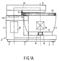
- FIG. 1a diagrammatically shows a kitchen machine according to the
- the kitchen machine shown in Figs. 1a and 1b is provided with a synthetic resin housing 1 which comprises a base 3 and a motor housing 5 arranged on the base 3.
- the base 3 is provided with a number of feet 7 with which the kitchen machine can be placed on a surface.
- An open synthetic resin bowl 9 can be placed on the base 3 next to the motor housing 5.
- a bearing bush 13 by means of which the bowl 9 is rotatably supported relative to a circular-cylindrical guide 15 provided on the base 3 is arranged below a bottom 11 of the bowl 9.
- a detachable transverse arm 17 is present on the motor housing 5 and extends substantially parallel to the base 3 above the open bowl 9.
- a rotatable tool 19 such as, for example, a mixing tool shown in Figs. 1a and 1b, which is detachably coupled to the transverse arm 17.
- a pinion 21 which has its rotation bearings in the transverse arm 17 is in engagement with a toothed rim 23 provided along an outer circumference of the bowl 9.
- the tool 19 and the pinion 21 are coupled to a transmission 25 which is shown diagrammatically only in Fig. 1a, which is arranged in the transverse arm 17, and which can be driven by an electric motor 27 accommodated in the motor housing 5.
- the tool 19 can thus be rotated in the bowl 9 by the electric motor 27, while the bowl 9 is rotatable relative to the base 3 by means of the electric motor 27.
- a further transparent bowl 29 can be placed on the base 3 instead of the open bowl 9, while a transparent blender 31 can be placed on the motor housing 5 instead of the transverse arm 17, so that the kitchen machine can be used in various assemblies.
- the further bowl 29 can be closed with a lid 33 which is provided with a feed tube 35 and which can be locked on the further bowl 29 by means of studs 39 which cooperate with slots 37 of the further bowl 29.
- the further bowl 29 can be locked on the base 3 by means of studs 41 which cooperate with slots 43 provided in said guide 15.
- a tool 45 is rotatable in the further bowl 29, for example a cutting tool shown in Figs. 2a and 2b, which tool can be exchanged after removal of the lid 33.
- the tool 45 is rotatably arranged relative to the further bowl 29 by means of a bush-shaped shaft 47 which is arranged around a central tube 49 of the further bowl 29, and a bearing bush 51 provided at the lid 33.
- the tool 45 is coupled to a first coupling bush 53 which has its rotation bearings in said guide 15 of the base 3 and can be driven by the electric motor 27 via a further transmission 55 arranged in the base 3 and shown diagrammatically only in Fig. 2a.
- the transparent blender 31 is provided with a lid 57 and a synthetic resin bottom part 59 which can be locked with four studs 61 in four slots 63 of the motor housing 5 cooperating with the studs 61.
- a tool 65 for example a mixing tool shown in Fig.
- a rotary switch 69 with which the electric motor 27 can be switched on is present at an upper side of the motor housing 5.
- the kitchen machine is provided with a blocking mechanism 71 which is diagrammatically shown in Figs. 3a and 4a and which blocks the rotary switch 69 in a zero position shown in Fig. 3a, in which the electric motor 27 is switched off, if the further bowl 29, the lid 33, or the blender 31 is absent or not correctly positioned.
- the blocking mechanism 71 for this purpose comprises two concentric annular slides 73 and 75 which are movably guided in two concentric annular guides 77 and 79 in the motor housing 5.
- the blocking mechanism 71 further comprises a straight slide 85 which is coupled to an arm 89 fastened to the rotary switch 69 by means of a pin-slot coupling 87.
- the slide 85 is movably guided in a straight guide 91 in the motor housing 5, which guide intersects the annular guides 77 and 79.
- the annular slides 73 and 75 are provided with bridge portions 93 and 95 which in the first position of the slides 73 and 75 shown in Fig. 3a extend through a recess 97 in the slide 85 visible in Fig.
- a stud 107 provided on the outermost annular slide 75 then comes into engagement with a recess 109 in the tag 103, so that the slide 75 is rotated against the pressure of the wire spring 83 into a second position shown in Fig. 4a in which a recess 111 provided in the bridge portion 95 of the slide 75 comes above the straight slide 85 (see Fig. 4c).
- the straight slide 85 is displaceable into a position shown in Figs. 4a, 4b and 4c through rotation of the rotary switch 69 into a position in which the electric motor 27 is switched on.
- a cover plate (not shown in the Figures) may be placed on the motor housing 5, which plate is provided with studs for cooperating with the slots 63 corresponding to the studs 61 of the blender 31.
- the kitchen machine may also be used while only the further bowl 29 with lid 33 has been placed through the placement of said cover plate.
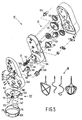
- the transverse arm 17 comprises a coupling piece 115 with which the transverse arm can be locked relative to the motor housing 5.
- the coupling piece 115 for this purpose comprises a locking mechanism 117 which is provided with a locking disc 119 which is arranged so as to be rotatable relative to the coupling piece 115.
- the locking disc 119 comprises four studs 121 which are capable of cooperating with the four slots 63 of the motor housing 5 and can be displaced by a user of the kitchen machine by means of a button 123 from a first position, in which the transverse arm 17 is unlocked from the motor housing 5, into a second position, in which the transverse arm 17 is locked to the motor housing 5.
- the coupling piece 115 and the locking mechanism 117 are capable of cooperating with the blocking mechanism 71 described above.
- the coupling piece 115 for this purpose comprises an oblique slot 125 visible in Fig. 5 which comes into engagement with a stud 127 provided on an inside of the outermost annular slide 75 (see Figs. 3a and 4a) upon the placement of the transverse arm 17 on the motor housing 5, so that the outermost slide 75 of the blocking mechanism 71 is moved from the first into the second position.
- one of the studs 121 of the locking disc 119 cooperates with the recess 99 in the innermost annular slide 73 shown in Figs.
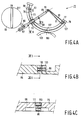
- the pinion 21 is coupled to a gear 129 belonging to the transmission 25.
- a number of gears 131, 133, 135 and 137 also belong to the transmission 25, to which various mixing, stirring, and kneading tools 19 can be coupled, as well as a coupling shaft 139 which can be coupled to the second coupling bush 67 upon the placement of the transverse arm 17 on the motor housing 5.
- the pinion 21 and the tools 19 can thus be driven by the electric motor 27 via the transmission 25.
- a shaft 141 of the pinion 21 is provided with a number of axial grooves 143 which are in engagement with a number of projections (not visible in the Figure) in a bush 145 of the gear 129.
- the pinion 21 as a result is slidable in axial direction relative to the gear 129.
- the pinion 21 is further provided along a circumference with a groove 147 which is in engagement with a fork 151 belonging to a slide 149.
- the slide 149 is displaceably guided between a lower outer shell 153 and a transmission frame 155 of the transverse arm 17 in a direction parallel to the axis of rotation of the pinion 21.
- the blocking stud 159 blocks one of the studs 121 of the locking disc 119, so that the locking disc 119 cannot be moved into the second position and the transverse arm 17 cannot be locked to the motor housing 5.
- the pinion 21 comes into engagement with the toothed rim 23 of the bowl 9.
- a collar 163 provided along a circumference of the pinion 21 then comes into pressure contact with a flank 165 of the toothed rim 23, so that the pinion 21 and the slide 149 are displaced parallel to the axis of rotation of the pinion 21 against the spring force of the blade spring 157 from the first position into a second position shown in Fig. 6b.
- the displacement of the slide 149 into the second position causes the blocking stud 159 to release the locking disc 119, so that the locking disc 119 can be moved into the second position in which the blocking mechanism 71 release the rotary switch 69.
- the transverse arm 17 can pivot relative to the motor housing 5.
- the transverse arm 17 is for this purpose provided with an elastic blade hinge 167 shown in Fig. 5 by means of which the lower outer shell 153 is fastened to the coupling piece 115.
- the locking disc 119 is provided with a hook 169 capable of cooperating with a T-shaped recess 171 provided in the lower outer shell 153.
- the transverse arm 17 is locked relative to the coupling piece 115 in the first and the second position of the locking disc 119 through engagement of the hook 169 in the recess 171, while the hook 169 releases the transverse arm 17 from the coupling piece 115 in an intermediate position of the locking disc 119 which is situated between the first and the second position and in which the coupling piece 115 is locked to the motor housing 5, as is the case in the second position of the locking disc 119.
- the coupling piece 115 of the transverse arm 17 is locked to the motor housing 5, while the hook 169 releases the transverse arm 17 relative to the coupling piece 115, so that the transverse arm 17 is pivotable relative to the coupling piece 115 and the motor housing 5.
- the tool 19 may be exchanged or cleaned, and the bowl 9 may be placed or removed.
- the rotary switch 69 is again blocked in the zero position by the blocking mechanism 71 which cooperates with the locking mechanism 117.
- the locking mechanism 117 In the pivoted position of the transverse arm 17, the locking mechanism 117 is also blocked in the intermediate position by the wire spring 173, so that the electric motor 27 cannot be switched on through rotation of the locking mechanism 117 into its second position while the transverse arm 17 is in the pivoted position, and the transverse arm 17 and the coupling piece 115 cannot be detached from the motor housing 5 through rotation of the locking mechanism 117 into the first position.
- the locking mechanism 117 cannot be brought from the intermediate position into the second position when the transverse arm 17 has not been pivoted, because the pinion 21 is in the first position.
- the rotary switch 69 then remains blocked in the zero position by the blocking mechanism 71, so that a user of the kitchen machine cannot injure himself with the rotating first coupling bush 53 or the rotating tool 19, if the bowl 9 was not placed, or an incorrect operation of the kitchen machine is prevented in the case in which the bowl 9 was placed incorrectly on the base 3.
- the pinion 21 thus has a dual function since the pinion 21 serves both as a drive wheel for the rotatable bowl 9 and as a mechanical presence detector for the bowl 9. A simple and effective construction of the kitchen machine with a minimum number of components is achieved thereby.
- the locking mechanism 117 When the electric motor 27 has been switched on with the locking mechanism 117 in the second position, the locking mechanism 117 is blocked in the second position by the blocking mechanism 71, so that it is not possible with the electric motor 27 switched on to pivot or detach the transverse arm 17 through rotation of the locking mechanism 117 into the intermediate or first position.
- the kitchen machine described above comprises a motor housing 5 which is arranged on a base 3 and in which an electric motor 27 is present, while the bowl 9 can be placed next to the motor housing 5. It is noted that the invention is also applicable to kitchen machines of a different construction such as, for example, a kitchen machine in which the transmission can be driven by the electric motor of a handmixer which can be placed on the transverse arm. The invention is also applicable to a kitchen machine having a transverse arm which cannot pivot but can be removed, or which can pivot but cannot be removed.
- a different type of drive wheel may be used instead of the pinion 21 such as, for example, a friction wheel which during operation bears on a smooth outer circumference of the bowl.
- the pinion 21 may alternatively drive the bowl 9 by means of a toothed rim provided along an inner circumference of the bowl 9.
- An axial displacement of the pinion 21 through engagement with the toothed rim 23 may also take place by an alternative method such, for example, the use of a conical pinion and a bevel gear rim.
- an alternative blocking mechanism for blocking the switch may be used.
- the blocking mechanism 71 is a dual blocking mechanism because the kitchen machine can be used simultaneously with the further bowl 29 and the blender 31.
- the blocking mechanism may be a single blocking mechanism.
- a pinion or alternative drive wheel may be used which cooperates directly with the blocking mechanism of the switch.
Landscapes
- Chemical & Material Sciences (AREA)
- Chemical Kinetics & Catalysis (AREA)
- Engineering & Computer Science (AREA)
- Mechanical Engineering (AREA)
- Food Science & Technology (AREA)
- Food-Manufacturing Devices (AREA)
- Centrifugal Separators (AREA)
- Disintegrating Or Milling (AREA)
- Formation And Processing Of Food Products (AREA)
Claims (10)
- Küchenmaschine mit einem Gehäuse (5), einer auf das Gehäuse stellbaren und gegenüber dem Gehäuse drehbargeführten Schale (9), und einem Ausleger (17), der gegenüber dem Gehäuse (5) verlagerbar ist, wobei in der Schale ein Werkzeug (19) vorgesehen werden kann, das mit einem in dem Ausleger (17) vorgesehenen und mit Hilfe eines Elektromotors (27) antreibbaren Getriebe (25) kuppelbar ist, während die Schale mittels eines Ritzels (21) antreibbar ist, das durch den Elektromotor (1) antreibbar ist und mit einem Umfang der Schale (9) zusammenarbeitet, dadurch gekennzeichnet, daß das Ritzel (21) über die Drehungsachse gegenüber dem Ausleger (17) zwischen einer ersten Lage und einer zweiten lage verlagerbar geführt ist, wobei das Ritzel beim Anbringen des Auslegers (17) auf dem Gehäuse durch Eingriff mit der Schale aus der ersten Lage in die zweite Lage verlagerbar ist, und ein mit dem Ritzel (21) zusammenarbeitender Sperrmechanismus (71) einen Schalter (69) des Elektromotors in der ersten Lage des Ritzels sperrt und in der zweiten Lage des Ritzels den Schalter freigibt.
- Küchenmaschine nach Anspruch 1, wobei das Antriebsrad ein Ritzel (21) ist, das mit einem Zahnkranz (23) am Umfang der Schale (9) zusammenarbeitet, dadurch gekennzeichnet, daß das Ritzel (21) mit einem Kragen versehen ist, der beim Anbringen des Auslegers (17) auf dem Gehäuse (5) mit einer Flanke des Zahnkranzes (23) in Druckkontakt gerät.
- Küchenmaschine nach Anspruch 1 oder 2, dadurch gekennzeichnet, daß das Ritzel (21) an einem Umfang mit einem Schlitz (147) versehen ist, der mit einer zu einem Schieber (149) gehörenden Gabel (151) im Eingriff ist, wobei der Schieber parallel zu der Drehungsachse des Ritzels verlagerbar und mit einem mit dem Sperrmechanismus (159) zusammenarbeitenden Sperrnocken (71) versehen ist.
- Küchenmaschine nach Anspruch 1, 2 oder 3, dadurch gekennzeichnet, daß der Ausleger (17) mit einem mit dem Sperrmechanismus (71) und mit dem verlagerbaren Ritzel (21) zusammenarbeitenden Verriegelungsmechanismus (117) versehen ist, der aus einer ersten Lage, worin der Ausleger von dem Gehäuse losgekuppelt ist, in eine zweite Lage verlagerbar ist, worin der Ausleger gegenüber dem Gehäuse verriegelt ist, wobei der Sperrmechanismus (71) den Schalter (69) des Elektromotors in der ersten Lage des Verriegelungsmechanismus sperrt und in der zweiten Lage des Verriegelungsmechanismus freigibt, während das Ritzel die zweite lage des Verriegelungsmechanismus erst freigibt, wenn das Ritzel sich in der zweiten Lage befindet.
- Küchenmaschine nach Anspruch 4, dadurch gekennzeichnet, daß der Verriegelungsmechanismus (117) eine drehbare Verriegelungsscheibe (119) aufweist, die mit entsprechenden Schlitzen (63) in dem Gehäuse (5) zusammenarbeitende Nocken (121) aufweist.
- Küchenmaschine nach Anspruch 4 oder 5, dadurch gekennzeichnet, daß der Ausleger (17) gegenüber einem den Verriegelungsmechanismus (117) umfassenden Kupplungsteil (115) gelenkig ist, mit dem der Ausleger gegenüber dem Gehäuse (5) verriegelbar ist, wobei ein zu dem Verriegelungsmechanismus (117) gehörender Haken (169) den Ausleger gegenüber dem Kupplungsteil (115) in der ersten und zweiten Lage des Verriegelungsmechanismus verriegelt und den Ausleger gegenüber dem Kupplungsteil in einer Zwischenlage zwischen der ersten und der zweiten Lage des Verriegelungsmechanismus freigibt.
- Küchenmaschine nach Anspruch 6, dadurch gekennzeichnet, daß der mit dem Verriegelungsmechanismus (117) zusammenarbeitende Sperrmechanismus (71) den Schalter (69) in der Zwischenlage des Verriegelungsmechanismus sperrt.
- Küchenmaschine nach Anspruch 6 oder 7, dadurch gekennzeichnet, daß der gelenkige Ausleger (17) mit einem weiteren Sperrelement zusammenarbeitet, das den Verriegelungsmechanismus in der Zwischen-lage sperrt, wenn der Ausleger gegenüber dem Kupplungsteil gelenkig ist.
- Küchenmaschine nach Anspruch 8, dadurch gekennzeichnet, daß das weitere Sperrelement eine Drahtfeder (173) ist, wobei diese Drahtfeder durch den Ausleger (17) elastisch verformt wird und den Verriegelungsmechanismus (117) freigibt, wenn der Ausleger gegenüber dem Kupplungsteil (115) verriegelt ist, während die Drahtfeder (173) frei wird und den Verriegelungsmechanismus (117) in der Zwischenlage sperrt, wenn der Ansleger gegenüber dem Kupplungsteil gelenkig ist.
- Küchenmaschine nach einem der Ansprüche 4 bis 9, dadurch gekennzeichnet, daß der Sperrmechanismus den Verriegelungsmechanismus (117) in der zweiten Lage sperrt, wenn der Elektromotor (27) mittels des Schalters eingeschaltet worden ist.
Priority Applications (1)
| Application Number | Priority Date | Filing Date | Title |
|---|---|---|---|
| EP95905738A EP0692945B1 (de) | 1994-02-07 | 1995-01-31 | Küchenmaschine mit gesichertem, drehbarem behälter |
Applications Claiming Priority (4)
| Application Number | Priority Date | Filing Date | Title |
|---|---|---|---|
| EP94200228 | 1994-02-07 | ||
| EP94200228 | 1994-02-07 | ||
| EP95905738A EP0692945B1 (de) | 1994-02-07 | 1995-01-31 | Küchenmaschine mit gesichertem, drehbarem behälter |
| PCT/IB1995/000062 WO1995020903A1 (en) | 1994-02-07 | 1995-01-31 | Kitchen machine with protected rotatable bowl |
Publications (2)
| Publication Number | Publication Date |
|---|---|
| EP0692945A1 EP0692945A1 (de) | 1996-01-24 |
| EP0692945B1 true EP0692945B1 (de) | 1998-09-16 |
Family
ID=8216617
Family Applications (1)
| Application Number | Title | Priority Date | Filing Date |
|---|---|---|---|
| EP95905738A Expired - Lifetime EP0692945B1 (de) | 1994-02-07 | 1995-01-31 | Küchenmaschine mit gesichertem, drehbarem behälter |
Country Status (7)
| Country | Link |
|---|---|
| US (1) | US5524530A (de) |
| EP (1) | EP0692945B1 (de) |
| JP (1) | JPH08508669A (de) |
| AT (1) | ATE171054T1 (de) |
| BR (1) | BR9505841A (de) |
| DE (1) | DE69504779T2 (de) |
| WO (1) | WO1995020903A1 (de) |
Families Citing this family (62)
| Publication number | Priority date | Publication date | Assignee | Title |
|---|---|---|---|---|
| FR2751859B1 (fr) * | 1996-08-01 | 1999-12-31 | Moulinex Sa | Support de batteur electromenager |
| DE19639582C2 (de) * | 1996-09-26 | 1998-10-01 | Braun Ag | Küchenmaschine |
| DE19646423A1 (de) * | 1996-11-11 | 1998-05-14 | Braun Ag | Küchenmaschine |
| US5934582A (en) * | 1997-01-06 | 1999-08-10 | Abledu; Kodzo O. | Food processing arrangement |
| US5806413A (en) * | 1997-03-31 | 1998-09-15 | Trovinger; Harry R. | Juicer |
| US5782558A (en) * | 1997-04-25 | 1998-07-21 | Sunbeam Products, Inc. | Headlock feature for stand mixer |
| WO1998058579A1 (en) * | 1997-06-23 | 1998-12-30 | Koninklijke Philips Electronics N.V. | Kitchen appliance having a drive unit adapted to be placed onto a container |
| WO1999037194A1 (en) * | 1998-01-05 | 1999-07-29 | Abledu Kodzo O | A title 14.01.00 |
| US5911505A (en) * | 1998-11-30 | 1999-06-15 | Hp Intellectual Corp. | Stand mixer with shaft coupling |
| FR2787311B1 (fr) | 1998-12-21 | 2001-01-26 | Seb Sa | Robot menager multifonctions |
| KR200258626Y1 (ko) * | 1999-06-30 | 2001-12-28 | 윤청목 | 쥬스추출기와 겸용 사용되게 한 믹서 |
| US6318683B1 (en) * | 1999-11-05 | 2001-11-20 | Adonica B. Savoy | Infant utensil having twist lock coupling |
| US6089143A (en) * | 1999-11-18 | 2000-07-18 | Figueroa; Carmina B. | Mashed potato machine |
| DE10016292A1 (de) * | 2000-03-31 | 2001-10-04 | Bsh Bosch Siemens Hausgeraete | Küchenmaschine |
| EP1286615A2 (de) | 2000-11-29 | 2003-03-05 | Koninklijke Philips Electronics N.V. | Küchengerät |
| USD453444S1 (en) | 2001-01-26 | 2002-02-12 | Hamilton Beach/Proctor-Silex, Inc. | Hand mixer |
| DE10121803A1 (de) * | 2001-05-04 | 2002-11-07 | Bsh Bosch Siemens Hausgeraete | Abdeckung für Haushaltsgerät, insbesondere Küchenmaschine |
| AUPR561101A0 (en) * | 2001-06-12 | 2001-07-12 | Sunbeam Corporation Limited | Food mixer |
| US7536108B2 (en) * | 2001-06-29 | 2009-05-19 | Nippon Telegraph & Telephone Corporation | High precision chromatic dispersion measuring method and automatic dispersion compensating optical link system that uses this method |
| US6761477B2 (en) * | 2002-06-28 | 2004-07-13 | Hamilton Beach/Proctor-Silex, Inc. | Mixer assembly with locking pivot head |
| US6629491B1 (en) * | 2002-12-12 | 2003-10-07 | Chiaphua Industries Limited | Cooking appliance |
| DE10261367A1 (de) * | 2002-12-30 | 2004-07-08 | BSH Bosch und Siemens Hausgeräte GmbH | Becheranordnung für eine Mischzerkleinerungsvorrichtung |
| US7175338B2 (en) | 2003-09-16 | 2007-02-13 | Viking Range Corporation | Stand mixer |
| USD499604S1 (en) | 2003-09-16 | 2004-12-14 | Viking Range Corporation | Stand mixer |
| USD499926S1 (en) | 2004-02-04 | 2004-12-21 | Societe Des Produits Nestle S.A. | Milk froth machine |
| FR2871042B1 (fr) * | 2004-06-08 | 2006-12-22 | Seb Sa | Friteuse a enduction automatique de matiere grasse |
| WO2006000700A2 (fr) * | 2004-06-08 | 2006-01-05 | Seb S.A. | Appareil de cuisson a flux d’air |
| TR200401889A2 (tr) * | 2004-07-29 | 2006-03-21 | Erna-Maş Makina Ti̇c. Ve San. A.Ş. | Mutfak robotu. |
| FR2885505B1 (fr) * | 2005-05-12 | 2007-06-22 | Seb Sa | Appareil electromenager de preparation culinaire comportant une trappe venant masquer un organe |
| GB2426559A (en) * | 2005-05-25 | 2006-11-29 | Martin John Nicholson | Apparatus for food processing |
| DE102005040525A1 (de) * | 2005-08-26 | 2007-03-01 | BSH Bosch und Siemens Hausgeräte GmbH | Küchengerät mit Sicherheitssystem und Verfahren zum Betreiben eines Küchengeräts |
| USD530146S1 (en) | 2005-09-09 | 2006-10-17 | Conair Corporation | Stand mixer |
| DE102006042982A1 (de) | 2006-09-13 | 2008-03-27 | BSH Bosch und Siemens Hausgeräte GmbH | Sicherheitsmechanismus für eine Küchenmaschine mit zwei Kupplungsstellen |
| DE102006042979B4 (de) | 2006-09-13 | 2009-06-18 | BSH Bosch und Siemens Hausgeräte GmbH | Küchenmaschine mit Entriegelungsknopf am Deckel |
| US7520453B2 (en) * | 2007-03-05 | 2009-04-21 | Hamilton Beach Brands, Inc. | Safety actuator for a food processor having a visual indication |
| US8122815B2 (en) * | 2007-04-20 | 2012-02-28 | Amy Wolfe | Device for stirring and cooking food |
| EP1989980A1 (de) * | 2007-05-11 | 2008-11-12 | Erna-Mas Makina Ticaret Ve Sanayi A.S. | Küchenroboter mit beweglicher Antriebseinheit |
| US8813635B2 (en) * | 2008-01-17 | 2014-08-26 | Marinela Luminita Dragan | Steam-heat-only, food-preparation bowl structure and related methodology |
| USD588864S1 (en) | 2008-10-28 | 2009-03-24 | Bullet Express, Llc | Blender |
| USD588863S1 (en) | 2008-10-28 | 2009-03-24 | Bullet Express, Llc | Blender |
| USD588400S1 (en) | 2008-10-28 | 2009-03-17 | Bullet Express, Llc | Blender |
| FR2940033B1 (fr) * | 2008-12-22 | 2013-03-29 | Seb Sa | Appareil electromenager de preparation culinaire comportant un premier et un deuxieme recipients de travail sur un boitier |
| US8438971B1 (en) | 2010-03-04 | 2013-05-14 | Sally Thurley | Stand mixer and heating means combination apparatus |
| EP2384847B1 (de) * | 2010-05-04 | 2018-07-04 | SANCASSIANO S.p.A. | Tank für Knetmaschine |
| TWD147104S (zh) | 2010-12-20 | 2012-05-11 | 寶貝快廚有限責任公司 | 廚房食物處理器容器 |
| TWD145039S (zh) | 2010-12-20 | 2012-01-11 | 寶貝快廚有限責任公司 | 食物貯存杯 |
| ES1075104Y (es) * | 2011-06-21 | 2011-11-11 | Sammic Sl | Maquina combinada procesadora de alimentos |
| US20140069282A1 (en) * | 2012-09-08 | 2014-03-13 | Zhengxu He | Automated stirring and mixing apparatus for cooking |
| JP5981781B2 (ja) * | 2012-06-20 | 2016-08-31 | 株式会社エム・アイ・ケー | 食品炒め機 |
| US9700177B2 (en) | 2013-03-01 | 2017-07-11 | Whirlpool Corporation | Food processing device jar lock |
| US9468339B2 (en) | 2013-03-15 | 2016-10-18 | Whirlpool Corporation | Low profile side drive blending appliance |
| US9555384B2 (en) * | 2013-10-25 | 2017-01-31 | Whirlpool Corporation | Blender assembly |
| US9815037B2 (en) | 2013-10-25 | 2017-11-14 | Whirlpook Corporation | Magnetic disc coupler |
| US9763542B2 (en) | 2014-03-13 | 2017-09-19 | Whirlpool Corporation | Anti-rotational latch for a blending appliance |
| US10092139B2 (en) | 2014-04-28 | 2018-10-09 | Whirlpool Corporation | Low profile motor for portable appliances |
| CN204071828U (zh) * | 2014-09-11 | 2015-01-07 | 江门市竞晖电器实业有限公司 | 一种可全方位搅拌的食物料理机 |
| US11039715B2 (en) * | 2017-07-05 | 2021-06-22 | Illinois Tool Works Inc. | Food processing machine adaptive to food load |
| TR201800849A2 (tr) * | 2018-01-22 | 2018-02-21 | Yazicilar Makina Sanayi Ve Ticaret Anonim Sirketi | Rulman yataği üzeri̇nden hazne ki̇li̇tleme si̇stemi̇ |
| EP4188172B1 (de) * | 2020-07-31 | 2025-05-07 | Circus Robotics GmbH | Vorrichtung und verfahren zum automatisierten zubereiten von nahrungsmitteln |
| US12440067B2 (en) * | 2022-04-21 | 2025-10-14 | Haier Us Appliance Solutions, Inc. | Systems for stand mixer assembly locating |
| US12213626B2 (en) | 2022-09-19 | 2025-02-04 | David Prokop | Pestle and bowl assembly |
| USD1110539S1 (en) | 2022-09-19 | 2026-01-27 | David Prokop | Pestle |
Family Cites Families (16)
| Publication number | Priority date | Publication date | Assignee | Title |
|---|---|---|---|---|
| US2075851A (en) * | 1934-04-07 | 1937-04-06 | Kitchenaid Mfg Company | Food handling apparatus |
| US3170674A (en) * | 1960-08-01 | 1965-02-23 | Mc Graw Edison Co | Household mixer |
| US3752057A (en) * | 1971-11-02 | 1973-08-14 | Dover Corp | Portable scraper-type mixer |
| US3951351A (en) * | 1974-06-13 | 1976-04-20 | Oster Corporation | Multi-purpose kitchen appliance |
| US3904178A (en) * | 1974-12-23 | 1975-09-09 | Sunbeam Corp | Household food mixer |
| NL7500397A (nl) * | 1975-01-14 | 1976-07-16 | Philips Nv | Tussenstuk voor mengapparaat. |
| US4325643A (en) * | 1980-07-11 | 1982-04-20 | Sunbeam Corporation | Food-mixing apparatus comprising a driving unit and a separable arm |
| US4403867A (en) * | 1980-10-20 | 1983-09-13 | Horace Duke | Ink and water tester |
| EP0063241A1 (de) * | 1981-04-03 | 1982-10-27 | Braun Aktiengesellschaft | Elektromotorisch betriebenes Antriebsaggregat, insbesondere für Mehrzweck-Küchenmaschinen |
| FR2596264B1 (fr) * | 1986-04-01 | 1988-10-07 | Moulinex Sa | Appareil electromenager pour preparations culinaires telles que sauces ou patisseries |
| US5417152A (en) * | 1991-12-20 | 1995-05-23 | Harrison; Robert G. | Speed controls |
| US5355784A (en) * | 1991-12-20 | 1994-10-18 | Trillium Health Products, Inc. | Juice extractors |
| FR2692463B1 (fr) * | 1992-06-17 | 1994-08-26 | Santos Sa | Appareil électrique pour le traitement de produits alimentaires, avec dispositif perfectionné de sécurité. |
| US5380086A (en) * | 1992-08-27 | 1995-01-10 | K-Tec, Inc. | Multipurpose food mixing appliance specially adapted for kneading dough |
| DE4310847C2 (de) * | 1993-04-02 | 1996-04-11 | Braun Ag | Antriebseinrichtung für eine Küchenmaschine |
| US5392699A (en) * | 1994-02-09 | 1995-02-28 | Tai; Chun-Ya L. | Vegetable and fruit juice processor and safety device thereof |
-
1995
- 1995-01-31 DE DE69504779T patent/DE69504779T2/de not_active Expired - Fee Related
- 1995-01-31 BR BR9505841A patent/BR9505841A/pt not_active IP Right Cessation
- 1995-01-31 JP JP7520483A patent/JPH08508669A/ja active Pending
- 1995-01-31 WO PCT/IB1995/000062 patent/WO1995020903A1/en not_active Ceased
- 1995-01-31 AT AT95905738T patent/ATE171054T1/de not_active IP Right Cessation
- 1995-01-31 EP EP95905738A patent/EP0692945B1/de not_active Expired - Lifetime
- 1995-02-07 US US08/386,905 patent/US5524530A/en not_active Expired - Fee Related
Also Published As
| Publication number | Publication date |
|---|---|
| US5524530A (en) | 1996-06-11 |
| EP0692945A1 (de) | 1996-01-24 |
| DE69504779D1 (de) | 1998-10-22 |
| DE69504779T2 (de) | 1999-04-22 |
| ATE171054T1 (de) | 1998-10-15 |
| WO1995020903A1 (en) | 1995-08-10 |
| BR9505841A (pt) | 1996-02-13 |
| JPH08508669A (ja) | 1996-09-17 |
Similar Documents
| Publication | Publication Date | Title |
|---|---|---|
| EP0692945B1 (de) | Küchenmaschine mit gesichertem, drehbarem behälter | |
| CA1144537A (en) | Multi blender-type container, electrically interlocked food mixing machine | |
| US5445332A (en) | Food processor | |
| US5000578A (en) | Food mixing appliance | |
| GB2158393A (en) | Scroller jig saw | |
| US5533801A (en) | Electrically operated hand mixer including an attachment | |
| GB2191555A (en) | Food processors | |
| US4422343A (en) | Kitchen appliance with interchangable attachments | |
| CN118356105A (zh) | 用于与厨用机器的基础设备的容纳区域相连接的制备容器 | |
| US5129589A (en) | Table-top multi-purpose device driven by means of an immersion blender | |
| CN102573587B (zh) | 旋转烹调装置 | |
| CN109998370B (zh) | 盖体组件及烹饪器具 | |
| CN100471431C (zh) | 具有一锁定装置及一安全装置且无盖件引位装置的家用烹饪电器 | |
| CN219331444U (zh) | 一种料理杯的安全解锁拆刀机构 | |
| GB2287176A (en) | Kitchen machine drive mechanism. | |
| CN217218812U (zh) | 食物料理机 | |
| GB1562070A (en) | Food preparing machine | |
| CN220459237U (zh) | 一种加工刀组件装配结构以及搅拌机 | |
| CN218791835U (zh) | 盖体组件及具有其的烹饪器具 | |
| JPH0217537Y2 (de) | ||
| JP3034182B2 (ja) | 調理器 | |
| JP2600132Y2 (ja) | 調理用カッター装置 | |
| CN116869377A (zh) | 一种加工刀组件装配结构以及搅拌机 | |
| JPH042312A (ja) | おろし装置 | |
| CN121795752A (zh) | 饮品机和冲泡座 |
Legal Events
| Date | Code | Title | Description |
|---|---|---|---|
| PUAI | Public reference made under article 153(3) epc to a published international application that has entered the european phase |
Free format text: ORIGINAL CODE: 0009012 |
|
| AK | Designated contracting states |
Kind code of ref document: A1 Designated state(s): AT DE FR GB IT |
|
| 17P | Request for examination filed |
Effective date: 19960212 |
|
| GRAG | Despatch of communication of intention to grant |
Free format text: ORIGINAL CODE: EPIDOS AGRA |
|
| 17Q | First examination report despatched |
Effective date: 19971117 |
|
| GRAG | Despatch of communication of intention to grant |
Free format text: ORIGINAL CODE: EPIDOS AGRA |
|
| GRAH | Despatch of communication of intention to grant a patent |
Free format text: ORIGINAL CODE: EPIDOS IGRA |
|
| GRAH | Despatch of communication of intention to grant a patent |
Free format text: ORIGINAL CODE: EPIDOS IGRA |
|
| GRAA | (expected) grant |
Free format text: ORIGINAL CODE: 0009210 |
|
| AK | Designated contracting states |
Kind code of ref document: B1 Designated state(s): AT DE FR GB IT |
|
| PG25 | Lapsed in a contracting state [announced via postgrant information from national office to epo] |
Ref country code: IT Free format text: LAPSE BECAUSE OF FAILURE TO SUBMIT A TRANSLATION OF THE DESCRIPTION OR TO PAY THE FEE WITHIN THE PRE;WARNING: LAPSES OF ITALIAN PATENTS WITH EFFECTIVE DATE BEFORE 2007 MAY HAVE OCCURRED AT ANY TIME BEFORE 2007. THE CORRECT EFFECTIVE DATE MAY BE DIFFERENT FROM THE ONE RECORDED.SCRIBED TIME-LIMIT Effective date: 19980916 Ref country code: AT Free format text: LAPSE BECAUSE OF FAILURE TO SUBMIT A TRANSLATION OF THE DESCRIPTION OR TO PAY THE FEE WITHIN THE PRESCRIBED TIME-LIMIT Effective date: 19980916 |
|
| REF | Corresponds to: |
Ref document number: 171054 Country of ref document: AT Date of ref document: 19981015 Kind code of ref document: T |
|
| REF | Corresponds to: |
Ref document number: 69504779 Country of ref document: DE Date of ref document: 19981022 |
|
| ET | Fr: translation filed | ||
| PLBE | No opposition filed within time limit |
Free format text: ORIGINAL CODE: 0009261 |
|
| STAA | Information on the status of an ep patent application or granted ep patent |
Free format text: STATUS: NO OPPOSITION FILED WITHIN TIME LIMIT |
|
| 26N | No opposition filed | ||
| PGFP | Annual fee paid to national office [announced via postgrant information from national office to epo] |
Ref country code: FR Payment date: 20010123 Year of fee payment: 7 |
|
| PGFP | Annual fee paid to national office [announced via postgrant information from national office to epo] |
Ref country code: GB Payment date: 20010130 Year of fee payment: 7 |
|
| PGFP | Annual fee paid to national office [announced via postgrant information from national office to epo] |
Ref country code: DE Payment date: 20010321 Year of fee payment: 7 |
|
| REG | Reference to a national code |
Ref country code: GB Ref legal event code: IF02 |
|
| PG25 | Lapsed in a contracting state [announced via postgrant information from national office to epo] |
Ref country code: GB Free format text: LAPSE BECAUSE OF NON-PAYMENT OF DUE FEES Effective date: 20020131 |
|
| PG25 | Lapsed in a contracting state [announced via postgrant information from national office to epo] |
Ref country code: DE Free format text: LAPSE BECAUSE OF NON-PAYMENT OF DUE FEES Effective date: 20020801 |
|
| GBPC | Gb: european patent ceased through non-payment of renewal fee |
Effective date: 20020131 |
|
| PG25 | Lapsed in a contracting state [announced via postgrant information from national office to epo] |
Ref country code: FR Free format text: LAPSE BECAUSE OF NON-PAYMENT OF DUE FEES Effective date: 20020930 |
|
| REG | Reference to a national code |
Ref country code: FR Ref legal event code: ST |