EP0693231B1 - Systeme d'accord pour laser a diode a cavite externe - Google Patents
Systeme d'accord pour laser a diode a cavite externe Download PDFInfo
- Publication number
- EP0693231B1 EP0693231B1 EP93923767A EP93923767A EP0693231B1 EP 0693231 B1 EP0693231 B1 EP 0693231B1 EP 93923767 A EP93923767 A EP 93923767A EP 93923767 A EP93923767 A EP 93923767A EP 0693231 B1 EP0693231 B1 EP 0693231B1
- Authority
- EP
- European Patent Office
- Prior art keywords
- mirror
- wavelength
- mounting means
- wavelengths
- cavity
- Prior art date
- Legal status (The legal status is an assumption and is not a legal conclusion. Google has not performed a legal analysis and makes no representation as to the accuracy of the status listed.)
- Expired - Lifetime
Links
- 230000003287 optical effect Effects 0.000 claims description 18
- 239000000463 material Substances 0.000 claims description 8
- 239000004065 semiconductor Substances 0.000 claims description 8
- 238000012937 correction Methods 0.000 claims description 5
- 238000009304 pastoral farming Methods 0.000 claims description 5
- 239000006185 dispersion Substances 0.000 description 10
- 230000000694 effects Effects 0.000 description 6
- 238000013519 translation Methods 0.000 description 5
- 230000008859 change Effects 0.000 description 3
- 238000000034 method Methods 0.000 description 3
- 230000001360 synchronised effect Effects 0.000 description 3
- 239000011810 insulating material Substances 0.000 description 2
- 230000009471 action Effects 0.000 description 1
- XAGFODPZIPBFFR-UHFFFAOYSA-N aluminium Chemical compound [Al] XAGFODPZIPBFFR-UHFFFAOYSA-N 0.000 description 1
- 229910052782 aluminium Inorganic materials 0.000 description 1
- 238000013459 approach Methods 0.000 description 1
- 239000011248 coating agent Substances 0.000 description 1
- 238000000576 coating method Methods 0.000 description 1
- 230000000052 comparative effect Effects 0.000 description 1
- 230000001419 dependent effect Effects 0.000 description 1
- 238000011161 development Methods 0.000 description 1
- 239000011521 glass Substances 0.000 description 1
- 238000001341 grazing-angle X-ray diffraction Methods 0.000 description 1
- 238000012423 maintenance Methods 0.000 description 1
- 230000007246 mechanism Effects 0.000 description 1
- 238000012986 modification Methods 0.000 description 1
- 230000004048 modification Effects 0.000 description 1
- 230000010355 oscillation Effects 0.000 description 1
- 239000004033 plastic Substances 0.000 description 1
- 239000004417 polycarbonate Substances 0.000 description 1
- 229920000515 polycarbonate Polymers 0.000 description 1
- 230000008569 process Effects 0.000 description 1
- 230000001681 protective effect Effects 0.000 description 1
- 230000003252 repetitive effect Effects 0.000 description 1
- 239000007787 solid Substances 0.000 description 1
- 230000007704 transition Effects 0.000 description 1
Images






Classifications
-
- H—ELECTRICITY
- H01—ELECTRIC ELEMENTS
- H01S—DEVICES USING THE PROCESS OF LIGHT AMPLIFICATION BY STIMULATED EMISSION OF RADIATION [LASER] TO AMPLIFY OR GENERATE LIGHT; DEVICES USING STIMULATED EMISSION OF ELECTROMAGNETIC RADIATION IN WAVE RANGES OTHER THAN OPTICAL
- H01S5/00—Semiconductor lasers
- H01S5/10—Construction or shape of the optical resonator, e.g. extended or external cavity, coupled cavities, bent-guide, varying width, thickness or composition of the active region
- H01S5/14—External cavity lasers
- H01S5/141—External cavity lasers using a wavelength selective device, e.g. a grating or etalon
- H01S5/143—Littman-Metcalf configuration, e.g. laser - grating - mirror
-
- H—ELECTRICITY
- H01—ELECTRIC ELEMENTS
- H01S—DEVICES USING THE PROCESS OF LIGHT AMPLIFICATION BY STIMULATED EMISSION OF RADIATION [LASER] TO AMPLIFY OR GENERATE LIGHT; DEVICES USING STIMULATED EMISSION OF ELECTROMAGNETIC RADIATION IN WAVE RANGES OTHER THAN OPTICAL
- H01S3/00—Lasers, i.e. devices using stimulated emission of electromagnetic radiation in the infrared, visible or ultraviolet wave range
- H01S3/10—Controlling the intensity, frequency, phase, polarisation or direction of the emitted radiation, e.g. switching, gating, modulating or demodulating
- H01S3/105—Controlling the intensity, frequency, phase, polarisation or direction of the emitted radiation, e.g. switching, gating, modulating or demodulating by controlling the mutual position or the reflecting properties of the reflectors of the cavity, e.g. by controlling the cavity length
-
- H—ELECTRICITY
- H01—ELECTRIC ELEMENTS
- H01S—DEVICES USING THE PROCESS OF LIGHT AMPLIFICATION BY STIMULATED EMISSION OF RADIATION [LASER] TO AMPLIFY OR GENERATE LIGHT; DEVICES USING STIMULATED EMISSION OF ELECTROMAGNETIC RADIATION IN WAVE RANGES OTHER THAN OPTICAL
- H01S5/00—Semiconductor lasers
- H01S5/02—Structural details or components not essential to laser action
- H01S5/022—Mountings; Housings
- H01S5/02208—Mountings; Housings characterised by the shape of the housings
-
- H—ELECTRICITY
- H01—ELECTRIC ELEMENTS
- H01S—DEVICES USING THE PROCESS OF LIGHT AMPLIFICATION BY STIMULATED EMISSION OF RADIATION [LASER] TO AMPLIFY OR GENERATE LIGHT; DEVICES USING STIMULATED EMISSION OF ELECTROMAGNETIC RADIATION IN WAVE RANGES OTHER THAN OPTICAL
- H01S5/00—Semiconductor lasers
- H01S5/02—Structural details or components not essential to laser action
- H01S5/022—Mountings; Housings
- H01S5/023—Mount members, e.g. sub-mount members
- H01S5/02325—Mechanically integrated components on mount members or optical micro-benches
Definitions
- This invention relates generally to tunable diode lasers, and particularly, to an improved tuning system which avoids tuning discontinuities by maintaining a constant integral number of half wavelengths in the tuning cavity over the entire tuning range.
- the typical tunable diode laser has one facet having an anti-reflection coating through which a selected wavelength is fed back into the laser to sustain oscillation at the selected wavelength.
- the desired wavelength is selected by means of a diffraction grating with a rotatable mirror which selects a desired wavelength from the beam diffracted by the grating.
- the variation in angle of the mirror is effective to select the desired wavelength, which is diffracted by the grating at the angle represented by the mirror position.
- the first order of diffraction of the grating is incident on the mirror, which reflects it back onto the grating, where the first order of diffraction passes back into the diode laser.
- the output of the system is the zeroth-order reflection from the grating. In this system, no mention is made of coordinated rotation and lineal translation of the mirror.
- the present invention provides an external cavity tunable laser diode system comprising:
- a semiconductor laser diode is positioned to illuminate a diffraction grating and a movable mirror is positioned to reflect a selected wavelength back into the laser cavity.
- the mirror is mounted on a pivot so positioned to provide simultaneous rotation and linear translation.
- the pivot point is selected so as to provide an internal cavity length which is exactly an integral number of half wavelengths at three different wavelengths and an exceptionally close (within 1/1000 of one wavelength) match at all other wavelengths within the tuning range.
- the pivot point calculation takes into account the effect of the dispersion of the laser and other optical elements in the system on the cavity length. These elements are usually a small part of the physical length of the cavity, but their greater dispersion makes their contribution to number of half wavelengths in the resonant cavity very significant.
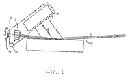
- a solid state diode laser 1 emits a beam with a nominal wavelength of 660 to 680 nanometers which passes through collimating lens 3 and illuminates grating 4 at a grazing angle.
- the zeroth-order reflection 5 from grating 4 is the output beam from the system.
- the first-order diffraction 6 from the grating 4 hits mirror 7 and is reflected back on to grating 4, from which it is returned to the laser 1 by a second diffraction.
- Mirror 7 is supported by mirror support arm 8, shown schematically by the broken line.
- Mirror support arm 8 has a socket 9 adapted to rotate on ball element 10, thereby allowing rotational movement of arm 8 and mirror 7. This showing is schematic only and is not intended to constitute an accurate geometric portrayal of the locations of the elements shown.
- one embodiment utilizes a type TOLD9215 diode laser sold by Toshiba.
- This laser has a physical length in the range of 200-300 microns and includes a window of 250-275 microns thickness.
- the lens 3 is a molded glass aspheric lens no. 350110 from Corning Glass selected to be 4.5 mm in thickness.
- Diffraction grating 4 may be of the holographic type having 2400 lines per mm, such as that sold by Edmund Scientific as number 43226.
- FIG. 2 is a side view of a preferred embodiment of the invention.
- Laser 1 is mounted on a base element 20 which also supports diffraction grating 4.
- Mirror support arm 8 is supported for rotational movement by a pair of pivot ball elements 10a and 10b, the latter of which is not shown.
- Pivot ball elements 10a and 10b are supported by matching socket portions in base 20 and mirror support arm 8 to permit rotational movement of mirror support arm 8 about an axis of rotation defined by the line connecting the centers of balls 10a and 10b.
- This method of supporting mirror support arm 8 provides for a low friction, high precision rotational mount.
- the angular and lineal position of mirror support arm 8 is adjusted by means of tuning screw 22 and piezoelectric actuator 23.
- Clockwise rotation of tuning screw 22 causes rotational movement of mirror support arm 8 in the counterclockwise direction about the center of pivot balls 10a and 10b.
- the application of a signal voltage to piezoelectric actuator 23 causes the actuator to extend or contract in length to provide a vernier and a high frequency, electrical adjustment of the position of mirror support arm 8. Voltage can also be applied to piezoelectric actuator 23 in a repetitive wave form to provide a scanning function.
- Rotational movement of mirror support arm 8 in the counterclockwise direction causes the angle of the reflected wave from grating 4 to be increased and the length of the cavity, from the rear of laser 1 to the mirror 7, to increase, thereby selecting a longer wavelength for operation of the system.
- clockwise rotation of mirror support arm 8 causes the output wavelength of the system to decrease.
- the operational wavelength of the system may be considered to be primarily determined by the angle of mirror 7 with respect to grating 4.
- the change in the cavity length caused by lineal translation of the mirror is primarily for the purpose of maintaining an integral number of half-wavelengths in the resonant cavity.
- Spring elements 30a-30b bias the mirror support arm 8 against the balls 10a and 10b.
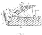
- FIG. 3 represents a sectional view taken from the side of the device along the center line. Since the system is sensitive to heat generated by laser 1, thermo electric coolers 31a and 31b are provided to conduct heat generated by laser 1 from the system. Alignment lever portions 32a and 32b (shown in FIG. 4) of mirror support arm 8 are provided to provide means for making the initial alignment of mirror 7 on the mirror support arm 8. Once the adjustment of mirror 7 has been made, no further adjustment of mirror position is required and the mirror is moved only with the tuning screw 22 and piezoelectric actuator 23.
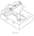
- FIG. 4A The isometric view of FIG. 4A shows the entire system of the preferred embodiment.
- Diffraction grating 4 is centrally positioned on the upper surface of base 20.
- the position of tuning screw 22 and piezoelectric actuator 23 is offset from the centerline of the system to provide clearance for the output beam incident on grating 4. Piezoelectric actuator 23 therefore engages mirror support arm 8 at a point offset from the center.
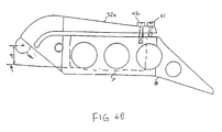
- a pair of fine threaded adjustment screws 41 and 42 provide means for adjusting the distance 43 to properly position the mirror with respect to the center of pivot ball 10a.
- the 0-80 adjustment screw 41 passes through a threaded hole in alignment lever 32a and bears against the upper surface of mirror support arm 8.
- the 0-80 adjustment screw 42 passes through a clearance hole in alignment lever 32a into a threaded hole in mirror support arm 8. Turning screw 41 clockwise causes distance 43 to increase. Conversely, turning screw 42 clockwise causes distance 43 to decrease. Since adjustment screws are provided on both sides of mirror support arm 8, optimal alignment of mirror 7 may be achieved without the need for exacting tolerances on the initial position of mirror 7.
- the preferred embodiment incorporates a shroud 50 of insulating material and a protective case 51a and 51b of suitable material such as aluminum or high tensile plastic such as fiber-reinforced polycarbonate.
- the case may include a removable cover 51a which fits over the base portion 51b.
- the base element 20 of the laser system will be affixed to the insulating material within base portion 51b of the case.
- An aperture 53 is provided in cover 51a for output beam 5.
- a transparent window is placed over the aperture 53, a gasket is placed between the base portion 51b and cover 51a, and all other openings in the case are sealed to prevent changes in air pressure and temperature from affecting the optical path length.
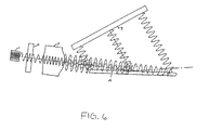
- the angular position of mirror 7 determines the particular angle of the first-order diffraction from the grating 4 which will be reflected back into laser 1. If the distance of mirror 7 is calculated according to simply the physical distance from the back mirror facet of laser 1, an error will exist because of the contribution of the various elements having different indices of refraction. This is illustrated schematically in FIG. 6 .
- the material of laser 1 has a relatively high index of refraction.
- window 2 and lens 3 also have high indices when compared to air. Because of the high index of refraction of these elements and the change of the index of refraction as a function of wavelength, i.e. dispersion, their contribution to the optical distance must be considered when calculating the lineal position of mirror 7.
- the physical distance must be corrected for the changes in the index of refraction (i.e., dispersion) of the optical elements and the air within the optical path, as well as the relatively simpler correction for the different wavelengths.
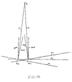
- FIG. 7A shows how the appropriate location for the pivot axis is established.
- the first step in the process is the calculation of the appropriate angle and lineal position for the mirror at various wavelengths of the operating range. This calculation proceeds according to the following:
- i ranges from 0 to 20; corresponding to wavelengths .660 to .680 microns.
- the calculation generates mirror positions for three different wavelengths.
- the three wavelengths represent the center wavelength of the tuning range and wavelengths on either side of the center wavelength slightly inside the limits of the tuning range.
- the mirror position for the center wavelength is shown at 70c
- the mirror position for the longer wavelength is shown at 701
- the mirror position for the shorter wavelength is shown at 70s.
- the plane in which each mirror lies is extended to the line where it intersects with another plane.
- the planes for mirror positions 70s and 70c intersect at point 70sc and the planes for mirror positions 701 and 70c intersect at point 701c.
- Normals 70sN and 70cN to the plane of mirror 70 and 70s are erected at the point 70sc and the bisector of the angle formed by the normals is extended along line 72.
- a similar exercise is performed for the intersection 701c of mirror planes for mirrors 701 and 70c.
- Normals 701N and 70cN to the plane of mirrors 701 and 70c are erected at the point 701c and the bisector of the angle formed by the normals is extended along line 73.
- the bisectors 72 and 73 intersect at point 75, which is the optimal location of the pivot point to provide the minimum distance error in the optical length of the tuning cavity. This is, to provide the same integral number of half-wavelengths in the tuning cavity over the entire operating range of the tuning system.
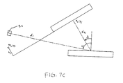
- FIG. 7B represents a portion of FIG. 7A redrawn to a larger scale with all reference characters in FIG. 7B representing the same element as in FIG. 7A.
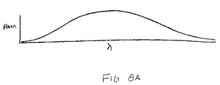
- FIG. 8A represents a plot of output power versus wavelength. While this is a theoretical plot, it is characteristic of systems embodying the present invention. It can be seen that the output power follows a smooth curve which rises toward the center of the operating wavelength and dips toward the higher and lower limits of the operating wavelength.
- FIG. 8B represents a plot of output power versus wavelength. It can be seen that the output power follows an airy function with the peaks representing integral numbers of half-wavelengths and the valleys representing the transition between the integral half wavelength points. The actual plot may differ somewhat from the theoretical form, but will never be a smooth curve such as shown in FIG. 8A.
- FIG. 9 represents a plot of the effect of dispersion versus wavelength.
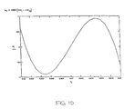
- FIG. 10 shows a plot of mirror position error versus wavelength. It can be seen that the system provides zero error at the three selected wavelengths and varies no more than 1/1000 of a wavelength over the operating range of the system.
- FIG. 11 illustrates the residual error for a system which does not compensate for dispersion, curve 110, and a system which incorporates the invention, curve 111.
- the vertical scale is the error in thousandths of a wavelength.
Landscapes
- Physics & Mathematics (AREA)
- Condensed Matter Physics & Semiconductors (AREA)
- General Physics & Mathematics (AREA)
- Electromagnetism (AREA)
- Optics & Photonics (AREA)
- Semiconductor Lasers (AREA)
- Lasers (AREA)
Claims (10)
- Système de diode laser accordable à cavité externe comprenant :caractérisé en ce que ledit moyen de montage (8) permet un mouvement linéaire et rotatif simultané dudit moyen formant miroir (7) autour d'un axe de rotation, axe de rotation qui est disposé de manière à correspondre à la ligne d'intersection de premier et second plans bissecteurs (72, 73), ledit premier plan bissecteur (72) étant projeté à partir de la ligne d'intersection (70sc) du plan de miroir dudit moyen formant miroir (7) au niveau d'une première position (70s) correspondant à une première longueur d'onde sélectionnée, et du plan de miroir dudit moyen formant miroir (7) au niveau d'une seconde position (70c) correspondant à une seconde longueur d'onde sélectionnée, ledit plan bissecteur coupant en deux l'angle défini entre les normales auxdits plans de miroir au niveau desdites première et seconde positions, normales qui sont élevées sur ladite ligne d'intersection (70sc), tandis que ledit second plan bissecteur (73) est projeté à partir d'une autre ligne d'intersection (701c) du plan de miroir dudit moyen formant miroir (7) au niveau de ladite seconde position (70c), et du plan de miroir dudit moyen formant miroir (7) au niveau d'une troisième position (701) correspondant à une troisième longueur d'onde sélectionnée, ledit second plan bissecteur coupant en deux l'angle défini entre les normales auxdits plans de miroir au niveau desdites seconde et troisième positions, normales qui sont élevées sur ladite autre ligne d'intersection (701c); en ce que chacune desdites première, seconde et troisième positions dudit moyen formant miroir est disposée de manière à fournir le même nombre entier de demi-longueurs d'onde à l'intérieur de la cavité résonnante; et en ce que la longueur optique de la cavité résonnante dudit système de diode laser accordable à cavité extérieure est calculée conformément à la formule :(a) un élément de base (20);(b) un moyen formant réseau de diffraction (4) monté sur ledit élément de base (20);(c) un moyen formant diode laser (1) monté sur ledit élément de base (20) et ayant un faisceau de sortie positionné pour traverser une lentille de collimation (3) et pour tomber sur ledit moyen formant réseau de diffraction (4) suivant un angle rasant;(d) un moyen formant miroir (7) destiné à renvoyer un faisceau diffracté par ledit moyen formant réseau de diffraction (4) sur ce dernier et, de là, dans ledit moyen formant diode laser;(e) un moyen de montage (8) sur lequel ledit moyen formant miroir (7) est monté;
- Opl =
- la longueur optique de la cavité résonnante
- Phl =
- la longueur physique de la cavité résonnante
correspondant à la distance entre la
facette de miroir arrière de la diode laser
et la surface de miroir dudit moyen formant
miroir (7) et C représentant une correction
de distance calculée conformément à la
formule :
- td =
- la longueur de la diode semi-conductrice
- ndi =
- l'indice de réfraction du matériau de la diode semi-conductrice
- tw =
- l'épaisseur de la fenêtre de la diode semi-conductrice
- nwi =
- l'indice de réfraction du matériau de la fenêtre
- tl =
- l'épaisseur de la lentille de collimation (3)
- nli =
- l'indice de réfraction du matériau de la lentille.
- Système selon la revendication 1, dans lequel ladite correction de distance C comprend une correction pour tenir compte d'éléments optiques supplémentaires présents dans ladite cavité de résonnance, correspondant aux longueurs et aux indices de réfraction desdits éléments supplémentaires, y compris de l'air.
- Système selon la revendication 1 ou 2, dans lequel lesdites première, seconde et troisième longueurs d'onde sélectionnées sont sélectionnées de façon que lesdites première et seconde longueurs d'onde soient espacées l'une de l'autre d'un nombre de longueurs d'onde approximativement égal au nombre de longueurs d'onde qui séparent lesdites seconde et troisième longueurs d'onde.
- Système selon la revendication 3, dans lequel ladite première longueur d'onde est nominalement une longueur d'onde proche de la longueur d'onde la plus courte du système, tandis que la troisième longueur d'onde est nominalement une longueur d'onde proche de la longueur d'onde la plus longue du système.
- Système selon la revendication 1, dans lequel la troisième desdites trois longueurs d'onde différentes est une longueur d'onde plus proche de la longueur d'onde la plus longue que ladite longueur d'onde centrale nominale, tandis que ladite première longueur d'onde est une longueur d'onde plus proche de la longueur d'onde la plus courte que ladite longueur d'onde centrale nominale.
- Système selon la revendication 1, dans lequel le moyen formant miroir est un miroir plan.
- Système selon la revendication 1, dans lequel ledit moyen de montage (8) pour ledit moyen formant miroir comprend:a. des première et seconde paires de coussinets positionnés dans une relation dans laquelle ils sont attenants audit élément de base (20) et audit moyen de montage (8) respectivement; etb. des premier et second éléments de roulement (10a, 10b) positionnés à l'intérieur desdits coussinets pour permettre un mouvement de rotation sur ledit moyen de montage (8) par rapport audit élément de base (20).
- Système selon la revendication 7, comprenant également un moyen élastique (30a, 30b) fixé audit élément de base (20) et audit moyen de montage (8) pour solliciter ce dernier contre lesdits éléments de roulement (10a, 10b).
- Système selon la revendication 7, dans lequel lesdits éléments de roulement (10a, 10b) sont de forme hémisphérique.
- Système selon la revendication 7, dans lequel ledit moyen de montage (8) comprend également :a. deux bras d'ajustement (32a, 32b) respectivement fixés audit moyen de montage (8) tout près de l'un de ladite seconde paire de coussinets et s'étendant vers l'extérieur depuis celui-ci jusqu'à un point espacé dudit moyen de montage (8); etb. chacun desdits bras d'ajustement (32a, 32b) comporte une première vis d'ajustement (42) traversant un trou de dégagement ménagé dans ledit bras d'ajustement pour pénétrer dans un trou taraudé ménagé dans ledit moyen de montage (8) à une première distance du point au niveau duquel ledit bras d'ajustement est fixé audit moyen de montage (8), et une seconde vis d'ajustement (41) traversant un trou taraudé ménagé dans ledit bras d'ajustement pour appuyer contre ledit moyen de montage (8) au niveau d'un point espacé d'une seconde distance, plus importante, du point au niveau duquel ledit bras d'ajustement est fixé audit moyen de montage, pour qu'ainsi ladite première vis (42) soit apte à agir pour dévier ledit moyen formant miroir (7) en direction dudit axe de rotation, tandis que la seconde vis (41) est apte à agir pour dévier ledit moyen formant miroir dans une direction opposée audit axe de rotation.
Applications Claiming Priority (3)
| Application Number | Priority Date | Filing Date | Title |
|---|---|---|---|
| US954398 | 1992-09-30 | ||
| US07/954,398 US5319668A (en) | 1992-09-30 | 1992-09-30 | Tuning system for external cavity diode laser |
| PCT/US1993/009428 WO1994008371A1 (fr) | 1992-09-30 | 1993-09-30 | Systeme d'accord pour laser a diode a cavite externe |
Publications (3)
| Publication Number | Publication Date |
|---|---|
| EP0693231A4 EP0693231A4 (fr) | 1995-10-18 |
| EP0693231A1 EP0693231A1 (fr) | 1996-01-24 |
| EP0693231B1 true EP0693231B1 (fr) | 1998-11-25 |
Family
ID=25495375
Family Applications (1)
| Application Number | Title | Priority Date | Filing Date |
|---|---|---|---|
| EP93923767A Expired - Lifetime EP0693231B1 (fr) | 1992-09-30 | 1993-09-30 | Systeme d'accord pour laser a diode a cavite externe |
Country Status (5)
| Country | Link |
|---|---|
| US (1) | US5319668A (fr) |
| EP (1) | EP0693231B1 (fr) |
| JP (1) | JPH08502144A (fr) |
| DE (1) | DE69322288T2 (fr) |
| WO (1) | WO1994008371A1 (fr) |
Families Citing this family (160)
| Publication number | Priority date | Publication date | Assignee | Title |
|---|---|---|---|---|
| US5422758A (en) * | 1993-09-08 | 1995-06-06 | Laser Machining, Inc. | Adjustable beam splitter |
| KR0128528B1 (ko) * | 1994-03-22 | 1998-04-07 | 신재인 | 쐐기형 프리즘(wedge prism)을 이용한 단일종모드 파장가변 레이저의 정밀파장조정(wavelength tuning) 방법과 장치 |
| FR2724496B1 (fr) * | 1994-09-13 | 1996-12-20 | Photonetics | Source laser monomode accordable en longueur d'onde a cavite externe autoalignee |
| US5524012A (en) * | 1994-10-27 | 1996-06-04 | New Focus, Inc. | Tunable, multiple frequency laser diode |
| GB9426242D0 (en) | 1994-12-24 | 1995-02-22 | Renishaw Plc | Laser diode for raman spectroscopy |
| DE19509922C2 (de) * | 1995-03-18 | 2001-02-22 | Joachim Sacher | Abstimmvorrichtung für einen Halbleiterlaser mit externem Resonator |
| DE19544897C2 (de) * | 1995-12-01 | 2000-10-12 | Hannover Laser Zentrum | Modensprungfrei abstimmbares Halbleiter-Lasersystem |
| US5771252A (en) * | 1996-01-29 | 1998-06-23 | Sdl, Inc. | External cavity, continuously tunable wavelength source |
| US5867512A (en) * | 1997-02-10 | 1999-02-02 | Sacher; Joachim | Tuning arrangement for a semiconductor diode laser with an external resonator |
| DE59709418D1 (de) * | 1996-04-10 | 2003-04-10 | Joachim Sacher | Abstimmvorrichtung |
| US6028667A (en) * | 1996-05-13 | 2000-02-22 | Process Instruments, Inc. | Compact and robust spectrograph |
| US6100975A (en) * | 1996-05-13 | 2000-08-08 | Process Instruments, Inc. | Raman spectroscopy apparatus and method using external cavity laser for continuous chemical analysis of sample streams |
| US5995521A (en) * | 1997-05-16 | 1999-11-30 | New Focus, Inc. | External cavity laser pivot design |
| US6040914A (en) * | 1997-06-10 | 2000-03-21 | New Focus, Inc. | Simple, low cost, laser absorption sensor system |
| US6192064B1 (en) * | 1997-07-01 | 2001-02-20 | Cymer, Inc. | Narrow band laser with fine wavelength control |
| DE19832750C2 (de) * | 1998-07-21 | 2000-06-08 | Lpkf Laser & Electronics Gmbh | Justierbares System eines Diodenlasers mit externem Resonator in der Littmann-Konfiguration |
| US6872984B1 (en) | 1998-07-29 | 2005-03-29 | Silicon Light Machines Corporation | Method of sealing a hermetic lid to a semiconductor die at an angle |
| US6303986B1 (en) | 1998-07-29 | 2001-10-16 | Silicon Light Machines | Method of and apparatus for sealing an hermetic lid to a semiconductor die |
| EP1149443A4 (fr) * | 1998-09-11 | 2006-03-22 | New Focus Inc | Laser accordable |
| US6282213B1 (en) | 1998-09-14 | 2001-08-28 | Interscience, Inc. | Tunable diode laser with fast digital line selection |
| US6108355A (en) * | 1998-10-16 | 2000-08-22 | New Focus, Inc. | Continuously-tunable external cavity laser |
| EP1159775B1 (fr) * | 1999-02-19 | 2004-09-01 | Radians Innova AB | Dispositif et procede de reglage de la longueur d'onde de la lumiere dans une cavite externe |
| US6879619B1 (en) | 1999-07-27 | 2005-04-12 | Intel Corporation | Method and apparatus for filtering an optical beam |
| US6853654B2 (en) * | 1999-07-27 | 2005-02-08 | Intel Corporation | Tunable external cavity laser |
| US6414973B1 (en) * | 1999-08-31 | 2002-07-02 | Ruey-Jen Hwu | High-power blue and green light laser generation from high powered diode lasers |
| US6856632B1 (en) | 1999-09-20 | 2005-02-15 | Iolon, Inc. | Widely tunable laser |
| US6847661B2 (en) | 1999-09-20 | 2005-01-25 | Iolon, Inc. | Tunable laser with microactuator |
| US6868099B1 (en) | 1999-11-04 | 2005-03-15 | Wisconsin Alumni Research Foundation | Frequency-narrowed high power diode laser system with external cavity |
| JP2001156393A (ja) | 1999-11-29 | 2001-06-08 | Ando Electric Co Ltd | V溝格子ミラー及びこれを用いた外部共振器型波長可変光源 |
| US6469415B2 (en) | 1999-11-29 | 2002-10-22 | Iolon, Inc. | Balanced microdevice and rotary electrostatic microactuator use therewith |
| US6903486B2 (en) * | 1999-11-29 | 2005-06-07 | Iolon, Inc. | Balanced microdevice |
| US6625183B1 (en) | 2000-01-31 | 2003-09-23 | New Focus, Inc. | External cavity laser apparatus |
| US6597449B1 (en) | 2000-01-31 | 2003-07-22 | New Focus, Inc. | Real time process control of optical components using linearly swept tunable laser |
| US6956878B1 (en) | 2000-02-07 | 2005-10-18 | Silicon Light Machines Corporation | Method and apparatus for reducing laser speckle using polarization averaging |
| US20010040910A1 (en) * | 2000-03-23 | 2001-11-15 | Zhang Guangzhi Z. | Continuously grating-tuned external cavity laser with automatic suppression of source spontaneous emission and amplified spontaneous emission |
| US7209498B1 (en) | 2000-05-04 | 2007-04-24 | Intel Corporation | Method and apparatus for tuning a laser |
| US6683895B2 (en) | 2000-07-26 | 2004-01-27 | Southwest Sciences Incorporated | Wavelength agile external cavity diode laser |
| US7120176B2 (en) * | 2000-07-27 | 2006-10-10 | Intel Corporation | Wavelength reference apparatus and method |
| US6584133B1 (en) | 2000-11-03 | 2003-06-24 | Wisconsin Alumni Research Foundation | Frequency-narrowed high power diode laser array method and system |
| JP2002190642A (ja) * | 2000-12-21 | 2002-07-05 | Ando Electric Co Ltd | 波長可変光源 |
| GB0101985D0 (en) * | 2001-01-25 | 2001-03-14 | Marconi Comm Ltd | Optical component |
| US6665320B1 (en) | 2001-01-29 | 2003-12-16 | Lightwave Electronics | Wideband tunable laser sources with multiple gain elements |
| US7177081B2 (en) | 2001-03-08 | 2007-02-13 | Silicon Light Machines Corporation | High contrast grating light valve type device |
| US6658031B2 (en) | 2001-07-06 | 2003-12-02 | Intel Corporation | Laser apparatus with active thermal tuning of external cavity |
| US6707591B2 (en) | 2001-04-10 | 2004-03-16 | Silicon Light Machines | Angled illumination for a single order light modulator based projection system |
| US6710914B2 (en) | 2001-05-22 | 2004-03-23 | Lightwave Electronics | Tunable light source employing optical parametric oscillation near degeneracy |
| EP1202409B1 (fr) * | 2001-06-01 | 2003-04-16 | Agilent Technologies, Inc. (a Delaware corporation) | Accorder un Laser |
| EP1202408B1 (fr) | 2001-06-01 | 2003-02-12 | Agilent Technologies, Inc. (a Delaware corporation) | Accorder un laser |
| US6865346B1 (en) | 2001-06-05 | 2005-03-08 | Silicon Light Machines Corporation | Fiber optic transceiver |
| US6782205B2 (en) | 2001-06-25 | 2004-08-24 | Silicon Light Machines | Method and apparatus for dynamic equalization in wavelength division multiplexing |
| US6747781B2 (en) | 2001-06-25 | 2004-06-08 | Silicon Light Machines, Inc. | Method, apparatus, and diffuser for reducing laser speckle |
| US6717964B2 (en) * | 2001-07-02 | 2004-04-06 | E20 Communications, Inc. | Method and apparatus for wavelength tuning of optically pumped vertical cavity surface emitting lasers |
| US6901088B2 (en) * | 2001-07-06 | 2005-05-31 | Intel Corporation | External cavity laser apparatus with orthogonal tuning of laser wavelength and cavity optical pathlength |
| US6822979B2 (en) | 2001-07-06 | 2004-11-23 | Intel Corporation | External cavity laser with continuous tuning of grid generator |
| US6724797B2 (en) | 2001-07-06 | 2004-04-20 | Intel Corporation | External cavity laser with selective thermal control |
| US6804278B2 (en) | 2001-07-06 | 2004-10-12 | Intel Corporation | Evaluation and adjustment of laser losses according to voltage across gain medium |
| US6788724B2 (en) * | 2001-07-06 | 2004-09-07 | Intel Corporation | Hermetically sealed external cavity laser system and method |
| US6914917B2 (en) * | 2001-07-24 | 2005-07-05 | Southwest Sciences Incorporated | Discrete wavelength-locked external cavity laser |
| US6665471B1 (en) | 2001-08-13 | 2003-12-16 | Nlight Photonics Corporation | System and method for optimizing the performance of multiple gain element laser |
| US6829092B2 (en) | 2001-08-15 | 2004-12-07 | Silicon Light Machines, Inc. | Blazed grating light valve |
| US6663785B1 (en) | 2001-08-31 | 2003-12-16 | Nlight Photonics Corporation | Broad spectrum emitter array and methods for fabrication thereof |
| US6657775B1 (en) | 2001-08-31 | 2003-12-02 | Nlight Photonics Corporation | System and method for providing a controlled linewidth external cavity laser |
| US6836487B1 (en) | 2001-08-31 | 2004-12-28 | Nlight Photonics Corporation | Spectrally tailored raman pump laser |
| US6907051B1 (en) | 2001-08-31 | 2005-06-14 | Nlight Photonics Corporation | Dynamically spectrally tailored raman pump laser |
| EP1231684A1 (fr) | 2001-09-07 | 2002-08-14 | Agilent Technologies, Inc. (a Delaware corporation) | Accorder un laser |
| EP1220389B1 (fr) * | 2001-09-07 | 2003-04-02 | Agilent Technologies, Inc. (a Delaware corporation) | Modification de la longuer du trajet optique utilisant un cristal liquide pour accorder un laser |
| US6930364B2 (en) | 2001-09-13 | 2005-08-16 | Silicon Light Machines Corporation | Microelectronic mechanical system and methods |
| US6956995B1 (en) | 2001-11-09 | 2005-10-18 | Silicon Light Machines Corporation | Optical communication arrangement |
| DE10158379B4 (de) * | 2001-11-28 | 2010-01-07 | Tem Messtechnik Gmbh | Monofrequent durchstimmbarer Halbleiterlaser mit thermisch abgeglichenen Komponenten |
| US7027469B2 (en) | 2001-11-30 | 2006-04-11 | Optitune Plc | Tunable filter |
| US6800238B1 (en) | 2002-01-15 | 2004-10-05 | Silicon Light Machines, Inc. | Method for domain patterning in low coercive field ferroelectrics |
| US7230959B2 (en) | 2002-02-22 | 2007-06-12 | Intel Corporation | Tunable laser with magnetically coupled filter |
| US6765733B1 (en) | 2002-03-14 | 2004-07-20 | Nlight Photonics Corporation | System and method for mounting components using ball and socket structure |
| US7317739B2 (en) * | 2002-03-15 | 2008-01-08 | Princeton University | Mode-locked laser using a mode-locking wavelength selective reflector |
| EP1502337B1 (fr) * | 2002-04-30 | 2008-10-22 | Agilent Technologies, Inc. | Source laser accordable en longueur d'onde a correction de parametres |
| US6690690B2 (en) | 2002-05-29 | 2004-02-10 | Lightgage, Inc. | Tunable laser system having an adjustable external cavity |
| US6728023B1 (en) | 2002-05-28 | 2004-04-27 | Silicon Light Machines | Optical device arrays with optimized image resolution |
| US7054515B1 (en) | 2002-05-30 | 2006-05-30 | Silicon Light Machines Corporation | Diffractive light modulator-based dynamic equalizer with integrated spectral monitor |
| US7061957B2 (en) * | 2002-06-04 | 2006-06-13 | Agilent Technologies, Inc. | External cavity laser having a set atmosphere |
| AU2003258951A1 (en) * | 2002-06-24 | 2004-01-06 | Lightgage, Inc. | Multi-stage data processing for frequency-scanning interferometer |
| US7130059B2 (en) * | 2002-06-24 | 2006-10-31 | Light Gage, Inc | Common-path frequency-scanning interferometer |
| US6829258B1 (en) | 2002-06-26 | 2004-12-07 | Silicon Light Machines, Inc. | Rapidly tunable external cavity laser |
| US6908201B2 (en) | 2002-06-28 | 2005-06-21 | Silicon Light Machines Corporation | Micro-support structures |
| AU2003247725A1 (en) | 2002-07-01 | 2004-01-19 | Lightgage, Inc. | Interferometer system of compact configuration |
| WO2004003464A2 (fr) * | 2002-07-01 | 2004-01-08 | Lightgage, Inc. | Interferometre a balayage de frequence dote d'une surface de reference non speculaire |
| US7057795B2 (en) | 2002-08-20 | 2006-06-06 | Silicon Light Machines Corporation | Micro-structures with individually addressable ribbon pairs |
| US6801354B1 (en) | 2002-08-20 | 2004-10-05 | Silicon Light Machines, Inc. | 2-D diffraction grating for substantially eliminating polarization dependent losses |
| US6712480B1 (en) | 2002-09-27 | 2004-03-30 | Silicon Light Machines | Controlled curvature of stressed micro-structures |
| US6731661B2 (en) * | 2002-10-01 | 2004-05-04 | Agilent Technologies, Inc. | Tuning mechanism for a tunable external-cavity laser |
| EP1330000A1 (fr) * | 2002-12-06 | 2003-07-23 | Agilent Technologies Inc | Détermination du point de fonctionnement pour un laser à sélection de modes |
| US6940879B2 (en) * | 2002-12-06 | 2005-09-06 | New Focus, Inc. | External cavity laser with dispersion compensation for mode-hop-free tuning |
| US6928207B1 (en) | 2002-12-12 | 2005-08-09 | Silicon Light Machines Corporation | Apparatus for selectively blocking WDM channels |
| US6987600B1 (en) | 2002-12-17 | 2006-01-17 | Silicon Light Machines Corporation | Arbitrary phase profile for better equalization in dynamic gain equalizer |
| US7057819B1 (en) | 2002-12-17 | 2006-06-06 | Silicon Light Machines Corporation | High contrast tilting ribbon blazed grating |
| US6934070B1 (en) | 2002-12-18 | 2005-08-23 | Silicon Light Machines Corporation | Chirped optical MEM device |
| US6927891B1 (en) | 2002-12-23 | 2005-08-09 | Silicon Light Machines Corporation | Tilt-able grating plane for improved crosstalk in 1×N blaze switches |
| US7245642B1 (en) | 2003-01-08 | 2007-07-17 | Southwest Sciences Incorporated | Broadband external cavity diode laser |
| US7068372B1 (en) | 2003-01-28 | 2006-06-27 | Silicon Light Machines Corporation | MEMS interferometer-based reconfigurable optical add-and-drop multiplexor |
| US7286764B1 (en) | 2003-02-03 | 2007-10-23 | Silicon Light Machines Corporation | Reconfigurable modulator-based optical add-and-drop multiplexer |
| US6947613B1 (en) | 2003-02-11 | 2005-09-20 | Silicon Light Machines Corporation | Wavelength selective switch and equalizer |
| US6922272B1 (en) | 2003-02-14 | 2005-07-26 | Silicon Light Machines Corporation | Method and apparatus for leveling thermal stress variations in multi-layer MEMS devices |
| US7391973B1 (en) | 2003-02-28 | 2008-06-24 | Silicon Light Machines Corporation | Two-stage gain equalizer |
| US6806997B1 (en) | 2003-02-28 | 2004-10-19 | Silicon Light Machines, Inc. | Patterned diffractive light modulator ribbon for PDL reduction |
| US6829077B1 (en) | 2003-02-28 | 2004-12-07 | Silicon Light Machines, Inc. | Diffractive light modulator with dynamically rotatable diffraction plane |
| US6922273B1 (en) | 2003-02-28 | 2005-07-26 | Silicon Light Machines Corporation | PDL mitigation structure for diffractive MEMS and gratings |
| US7027202B1 (en) | 2003-02-28 | 2006-04-11 | Silicon Light Machines Corp | Silicon substrate as a light modulator sacrificial layer |
| US7042611B1 (en) | 2003-03-03 | 2006-05-09 | Silicon Light Machines Corporation | Pre-deflected bias ribbons |
| US7286582B1 (en) | 2003-10-08 | 2007-10-23 | Fay Jr Theodore Denis | Optical external cavities having brewster angle wedges |
| US7889776B2 (en) * | 2004-01-20 | 2011-02-15 | Trumpf Photonics Inc. | High-power semiconductor laser |
| US8989523B2 (en) | 2004-01-22 | 2015-03-24 | Vescent Photonics, Inc. | Liquid crystal waveguide for dynamically controlling polarized light |
| US8463080B1 (en) | 2004-01-22 | 2013-06-11 | Vescent Photonics, Inc. | Liquid crystal waveguide having two or more control voltages for controlling polarized light |
| US8860897B1 (en) | 2004-01-22 | 2014-10-14 | Vescent Photonics, Inc. | Liquid crystal waveguide having electric field orientated for controlling light |
| US20050271325A1 (en) * | 2004-01-22 | 2005-12-08 | Anderson Michael H | Liquid crystal waveguide having refractive shapes for dynamically controlling light |
| US7720116B2 (en) * | 2004-01-22 | 2010-05-18 | Vescent Photonics, Inc. | Tunable laser having liquid crystal waveguide |
| US20050163172A1 (en) * | 2004-01-27 | 2005-07-28 | Joachim Sacher | High-power laser diode arrangement with external resonator |
| JP4073886B2 (ja) * | 2004-03-30 | 2008-04-09 | アンリツ株式会社 | 可変波長光源 |
| US7260122B2 (en) * | 2004-11-24 | 2007-08-21 | Wisconsin Alumni Research Foundation | Modeless wavelength-agile laser |
| US7199924B1 (en) * | 2005-01-26 | 2007-04-03 | Aculight Corporation | Apparatus and method for spectral-beam combining of high-power fiber lasers |
| US7233442B1 (en) * | 2005-01-26 | 2007-06-19 | Aculight Corporation | Method and apparatus for spectral-beam combining of high-power fiber lasers |
| US7653094B2 (en) * | 2005-03-24 | 2010-01-26 | Mitutoyo Corporation | External cavity laser with flexure tuning element |
| US20060227820A1 (en) * | 2005-03-30 | 2006-10-12 | Coherix, Inc. | Tunable laser |
| US20060227821A1 (en) * | 2005-03-30 | 2006-10-12 | Coherix, Inc. | Tunable laser |
| US7391561B2 (en) | 2005-07-29 | 2008-06-24 | Aculight Corporation | Fiber- or rod-based optical source featuring a large-core, rare-earth-doped photonic-crystal device for generation of high-power pulsed radiation and method |
| US7430352B2 (en) | 2005-07-29 | 2008-09-30 | Aculight Corporation | Multi-segment photonic-crystal-rod waveguides for amplification of high-power pulsed optical radiation and associated method |
| US7570320B1 (en) | 2005-09-01 | 2009-08-04 | Vescent Photonics, Inc. | Thermo-optic liquid crystal waveguides |
| WO2007103898A2 (fr) * | 2006-03-03 | 2007-09-13 | Aculight Corporation | Module de pompage par diodes laser à ports de signaux intégrés utilisés pour pomper des fibres amplificatrices |
| US7768700B1 (en) | 2006-11-30 | 2010-08-03 | Lockheed Martin Corporation | Method and apparatus for optical gain fiber having segments of differing core sizes |
| US8179594B1 (en) | 2007-06-29 | 2012-05-15 | Lockheed Martin Corporation | Method and apparatus for spectral-beam combining of fanned-in laser beams with chromatic-dispersion compensation using a plurality of diffractive gratings |
| US8284489B2 (en) * | 2007-09-11 | 2012-10-09 | Aegis Lightwave, Inc. | Spectrally adjustable filter |
| US20090229651A1 (en) * | 2008-03-14 | 2009-09-17 | Fay Jr Theodore Denis | Solar energy production system |
| US9366938B1 (en) * | 2009-02-17 | 2016-06-14 | Vescent Photonics, Inc. | Electro-optic beam deflector device |
| US8526110B1 (en) | 2009-02-17 | 2013-09-03 | Lockheed Martin Corporation | Spectral-beam combining for high-power fiber-ring-laser systems |
| EP2524260A4 (fr) * | 2009-08-11 | 2013-07-24 | Chromx Llc | Microscope à fond ultrasombre |
| US8503840B2 (en) | 2010-08-23 | 2013-08-06 | Lockheed Martin Corporation | Optical-fiber array method and apparatus |
| US8441718B2 (en) * | 2009-11-23 | 2013-05-14 | Lockheed Martin Corporation | Spectrally beam combined laser system and method at eye-safer wavelengths |
| JP5637474B2 (ja) * | 2009-12-30 | 2014-12-10 | 国立大学法人 千葉大学 | ビームフィルタ、それを備えたレーザチップ及び外部共振器レーザ |
| US9042422B2 (en) | 2009-12-30 | 2015-05-26 | National University Corporation Chiba University | Tunable external resonator laser |
| DE112011101288T5 (de) | 2010-04-12 | 2013-02-07 | Lockheed Martin Corporation | Strahldiagnostik- und Rückkopplungssystem sowie Verfahren für spektralstrahlkombinierteLaser |
| US8995038B1 (en) | 2010-07-06 | 2015-03-31 | Vescent Photonics, Inc. | Optical time delay control device |
| RU2525578C2 (ru) * | 2012-07-10 | 2014-08-20 | Федеральное государственное автономное образовательное учреждение высшего профессионального образования "Казанский (Приволжский) Федеральный Университет" (ФГАОУ ВПО КФУ) | Способ вывода и регулирования энергии/мощности выходного излучения лазера и устройство для его реализации |
| WO2014046161A1 (fr) | 2012-09-21 | 2014-03-27 | 国立大学法人 千葉大学 | Laser de résonateur externe |
| JP6118986B2 (ja) | 2013-01-30 | 2017-04-26 | サンテック株式会社 | 眼科用光断層画像表示装置 |
| US9147995B2 (en) * | 2013-03-15 | 2015-09-29 | Daylight Solutions, Inc. | Rapidly tunable laser source assembly with long stroke grating mover |
| US9835778B1 (en) | 2013-09-13 | 2017-12-05 | Lockheed Martin Corporation | Apparatus and method for a diamond substrate for a multi-layered dielectric diffraction grating |
| US9366872B2 (en) | 2014-02-18 | 2016-06-14 | Lockheed Martin Corporation | Apparatus and method for fiber-laser output-beam shaping for spectral beam combination |
| US10869623B2 (en) | 2014-05-28 | 2020-12-22 | Santec Corporation | Non-invasive optical measurement of blood analyte |
| US10548520B2 (en) | 2015-04-01 | 2020-02-04 | Santec Corporation | Non-invasive optical measurement of blood analyte |
| WO2016196463A1 (fr) | 2015-06-01 | 2016-12-08 | Santec Corporation | Système de tomographie par cohérence optique combinant deux longueurs d'onde |
| US10677580B2 (en) | 2016-04-27 | 2020-06-09 | Santec Corporation | Optical coherence tomography system using polarization switching |
| US9993153B2 (en) | 2016-07-06 | 2018-06-12 | Santec Corporation | Optical coherence tomography system and method with multiple apertures |
| US10426337B2 (en) | 2017-06-01 | 2019-10-01 | Santec Corporation | Flow imaging in an optical coherence tomography (OCT) system |
| US10408600B2 (en) | 2017-06-22 | 2019-09-10 | Santec Corporation | Optical coherence tomography with a fizeau-type interferometer |
| US10206567B2 (en) | 2017-07-12 | 2019-02-19 | Santec Corporation | Dual wavelength resampling system and method |
| US10502546B2 (en) | 2017-11-07 | 2019-12-10 | Santec Corporation | Systems and methods for variable-range fourier domain imaging |
| US11213200B2 (en) | 2018-03-22 | 2022-01-04 | Santec Corporation | Topographical imaging using combined sensing inputs |
| US10838047B2 (en) | 2018-04-17 | 2020-11-17 | Santec Corporation | Systems and methods for LIDAR scanning of an environment over a sweep of wavelengths |
| US11067671B2 (en) | 2018-04-17 | 2021-07-20 | Santec Corporation | LIDAR sensing arrangements |
| US20230221440A1 (en) * | 2022-01-10 | 2023-07-13 | Beijing Voyager Technology Co., Ltd. | Synchronized beam scanning and wavelength tuning |
| US12438340B2 (en) * | 2022-11-15 | 2025-10-07 | O-Net Communications, Inc. | Ultra small packaged tunable laser assembly |
| US12313883B2 (en) | 2023-03-03 | 2025-05-27 | santec Holdings Corporation | Photonic beam steering device with wavelength sweep |
Family Cites Families (9)
| Publication number | Priority date | Publication date | Assignee | Title |
|---|---|---|---|---|
| GB8807385D0 (en) * | 1988-03-29 | 1988-05-05 | British Telecomm | Semiconductor device assembly |
| US4937448A (en) * | 1988-05-26 | 1990-06-26 | Spectra-Physics, Inc. | Self-normalizing single-beam laser spectrometer |
| US4896325A (en) * | 1988-08-23 | 1990-01-23 | The Regents Of The University Of California | Multi-section tunable laser with differing multi-element mirrors |
| US4943971A (en) * | 1989-02-24 | 1990-07-24 | Spectra-Physics, Inc. | Low tuning rate single mode PbTe/PbEuSeTe buried heterostructure tunable diode lasers and arrays |
| US5028563A (en) * | 1989-02-24 | 1991-07-02 | Laser Photonics, Inc. | Method for making low tuning rate single mode PbTe/PbEuSeTe buried heterostructure tunable diode lasers and arrays |
| US4990780A (en) * | 1989-06-19 | 1991-02-05 | General Motors Corporation | Method for determining fuel and engine oil comsumption using tunable diode laser spectroscopy |
| JP2898016B2 (ja) * | 1989-06-23 | 1999-05-31 | 新日本製鐵株式会社 | メモリ装置 |
| US5022038A (en) * | 1989-12-28 | 1991-06-04 | General Dynamics Corp./Electronics Division | Wavelength tunable diode laser |
| US5103453A (en) * | 1991-02-12 | 1992-04-07 | Aerodyne Research, Inc. | Method and means for controlling the frequency and power output of a tunable diode laser |
-
1992
- 1992-09-30 US US07/954,398 patent/US5319668A/en not_active Expired - Lifetime
-
1993
- 1993-09-30 DE DE69322288T patent/DE69322288T2/de not_active Expired - Lifetime
- 1993-09-30 EP EP93923767A patent/EP0693231B1/fr not_active Expired - Lifetime
- 1993-09-30 JP JP6509368A patent/JPH08502144A/ja active Pending
- 1993-09-30 WO PCT/US1993/009428 patent/WO1994008371A1/fr not_active Ceased
Also Published As
| Publication number | Publication date |
|---|---|
| DE69322288D1 (de) | 1999-01-07 |
| JPH08502144A (ja) | 1996-03-05 |
| US5319668A (en) | 1994-06-07 |
| WO1994008371A1 (fr) | 1994-04-14 |
| DE69322288T2 (de) | 1999-05-06 |
| EP0693231A4 (fr) | 1995-10-18 |
| EP0693231A1 (fr) | 1996-01-24 |
Similar Documents
| Publication | Publication Date | Title |
|---|---|---|
| US5319668A (en) | Tuning system for external cavity diode laser | |
| US5594744A (en) | Singlemode laser source tunable in wavelength with a self-aligned external cavity | |
| US5867512A (en) | Tuning arrangement for a semiconductor diode laser with an external resonator | |
| US6026100A (en) | External cavity-type of wavelength tunable semiconductor laser light source and method for tuning wavelength therefor | |
| US6018535A (en) | External cavity type wavelength-tunable light source | |
| US5331651A (en) | Method and apparatus for adjusting the wavelength in an optical device and laser using the method | |
| US7733925B2 (en) | Continuous wavelength tunable laser source with optimum positioning of pivot axis for grating | |
| EP0491777B1 (fr) | Procede d'obtention d'une syntonisation exempte de saut de mode d'une frequence de resonance et de la valeur q d'un resonateur optique, et dispositif de mise en oeuvre du procede | |
| US5982794A (en) | External resonator type of variable-wavelength semiconductor laser light source | |
| US7031353B2 (en) | Apparatus and method for adjusting external-cavity lasers | |
| US5995521A (en) | External cavity laser pivot design | |
| Zhang et al. | Continuous wavelength tuning in micromachined Littrow external-cavity lasers | |
| US6192059B1 (en) | Wavelength-tunable laser configuration | |
| US7653094B2 (en) | External cavity laser with flexure tuning element | |
| US6731661B2 (en) | Tuning mechanism for a tunable external-cavity laser | |
| US5619318A (en) | Optical displacement sensor | |
| JPH1168248A (ja) | 外部共振器型波長可変半導体レーザ光源 | |
| WO2001073905A1 (fr) | Ajustement de longueur d'onde dans un laser a cavite externe | |
| JPH0897516A (ja) | 波長安定化外部共振器型ld光源 | |
| JP2005175049A (ja) | 外部共振器型半導体レーザ | |
| US4048585A (en) | Tuning type laser oscillator apparatus and laser radar system and laser communication system using the same | |
| JPH09129982A (ja) | 外部共振器型ld光源 | |
| US20060227821A1 (en) | Tunable laser | |
| US20110261843A1 (en) | Grating external-cavity semiconductor laser and quasi-synchronous tuning method thereof | |
| Laurila et al. | External cavity diode laser based on a transmission grating |
Legal Events
| Date | Code | Title | Description |
|---|---|---|---|
| A4 | Supplementary search report drawn up and despatched | ||
| AK | Designated contracting states |
Kind code of ref document: A4 Designated state(s): DE FR GB NL |
|
| PUAI | Public reference made under article 153(3) epc to a published international application that has entered the european phase |
Free format text: ORIGINAL CODE: 0009012 |
|
| 17P | Request for examination filed |
Effective date: 19950331 |
|
| AK | Designated contracting states |
Kind code of ref document: A1 Designated state(s): DE FR GB NL |
|
| 17Q | First examination report despatched |
Effective date: 19970122 |
|
| GRAG | Despatch of communication of intention to grant |
Free format text: ORIGINAL CODE: EPIDOS AGRA |
|
| GRAG | Despatch of communication of intention to grant |
Free format text: ORIGINAL CODE: EPIDOS AGRA |
|
| GRAG | Despatch of communication of intention to grant |
Free format text: ORIGINAL CODE: EPIDOS AGRA |
|
| GRAH | Despatch of communication of intention to grant a patent |
Free format text: ORIGINAL CODE: EPIDOS IGRA |
|
| RAP1 | Party data changed (applicant data changed or rights of an application transferred) |
Owner name: NEW FOCUS, INC. |
|
| RIN1 | Information on inventor provided before grant (corrected) |
Inventor name: LUECKE, FRANCIS S. |
|
| GRAH | Despatch of communication of intention to grant a patent |
Free format text: ORIGINAL CODE: EPIDOS IGRA |
|
| GRAA | (expected) grant |
Free format text: ORIGINAL CODE: 0009210 |
|
| AK | Designated contracting states |
Kind code of ref document: B1 Designated state(s): DE FR GB NL |
|
| PG25 | Lapsed in a contracting state [announced via postgrant information from national office to epo] |
Ref country code: NL Free format text: LAPSE BECAUSE OF FAILURE TO SUBMIT A TRANSLATION OF THE DESCRIPTION OR TO PAY THE FEE WITHIN THE PRESCRIBED TIME-LIMIT Effective date: 19981125 |
|
| REF | Corresponds to: |
Ref document number: 69322288 Country of ref document: DE Date of ref document: 19990107 |
|
| ET | Fr: translation filed | ||
| NLV1 | Nl: lapsed or annulled due to failure to fulfill the requirements of art. 29p and 29m of the patents act | ||
| PLBE | No opposition filed within time limit |
Free format text: ORIGINAL CODE: 0009261 |
|
| STAA | Information on the status of an ep patent application or granted ep patent |
Free format text: STATUS: NO OPPOSITION FILED WITHIN TIME LIMIT |
|
| 26N | No opposition filed | ||
| REG | Reference to a national code |
Ref country code: GB Ref legal event code: IF02 |
|
| PGFP | Annual fee paid to national office [announced via postgrant information from national office to epo] |
Ref country code: FR Payment date: 20060908 Year of fee payment: 14 |
|
| REG | Reference to a national code |
Ref country code: FR Ref legal event code: ST Effective date: 20080531 |
|
| PG25 | Lapsed in a contracting state [announced via postgrant information from national office to epo] |
Ref country code: FR Free format text: LAPSE BECAUSE OF NON-PAYMENT OF DUE FEES Effective date: 20071001 |
|
| PGFP | Annual fee paid to national office [announced via postgrant information from national office to epo] |
Ref country code: GB Payment date: 20100927 Year of fee payment: 18 |
|
| PGFP | Annual fee paid to national office [announced via postgrant information from national office to epo] |
Ref country code: DE Payment date: 20100929 Year of fee payment: 18 |
|
| GBPC | Gb: european patent ceased through non-payment of renewal fee |
Effective date: 20110930 |
|
| REG | Reference to a national code |
Ref country code: DE Ref legal event code: R119 Ref document number: 69322288 Country of ref document: DE Effective date: 20120403 |
|
| PG25 | Lapsed in a contracting state [announced via postgrant information from national office to epo] |
Ref country code: DE Free format text: LAPSE BECAUSE OF NON-PAYMENT OF DUE FEES Effective date: 20120403 |
|
| PG25 | Lapsed in a contracting state [announced via postgrant information from national office to epo] |
Ref country code: GB Free format text: LAPSE BECAUSE OF NON-PAYMENT OF DUE FEES Effective date: 20110930 |