EP0693809A2 - Modengekoppelter Faserringlaser - Google Patents
Modengekoppelter Faserringlaser Download PDFInfo
- Publication number
- EP0693809A2 EP0693809A2 EP95111416A EP95111416A EP0693809A2 EP 0693809 A2 EP0693809 A2 EP 0693809A2 EP 95111416 A EP95111416 A EP 95111416A EP 95111416 A EP95111416 A EP 95111416A EP 0693809 A2 EP0693809 A2 EP 0693809A2
- Authority
- EP
- European Patent Office
- Prior art keywords
- mode
- optical
- las
- ring laser
- fiber ring
- Prior art date
- Legal status (The legal status is an assumption and is not a legal conclusion. Google has not performed a legal analysis and makes no representation as to the accuracy of the status listed.)
- Granted
Links
Images


Classifications
-
- H—ELECTRICITY
- H01—ELECTRIC ELEMENTS
- H01S—DEVICES USING THE PROCESS OF LIGHT AMPLIFICATION BY STIMULATED EMISSION OF RADIATION [LASER] TO AMPLIFY OR GENERATE LIGHT; DEVICES USING STIMULATED EMISSION OF ELECTROMAGNETIC RADIATION IN WAVE RANGES OTHER THAN OPTICAL
- H01S3/00—Lasers, i.e. devices using stimulated emission of electromagnetic radiation in the infrared, visible or ultraviolet wave range
- H01S3/10—Controlling the intensity, frequency, phase, polarisation or direction of the emitted radiation, e.g. switching, gating, modulating or demodulating
- H01S3/13—Stabilisation of laser output parameters, e.g. frequency or amplitude
- H01S3/136—Stabilisation of laser output parameters, e.g. frequency or amplitude by controlling devices placed within the cavity
-
- H—ELECTRICITY
- H01—ELECTRIC ELEMENTS
- H01S—DEVICES USING THE PROCESS OF LIGHT AMPLIFICATION BY STIMULATED EMISSION OF RADIATION [LASER] TO AMPLIFY OR GENERATE LIGHT; DEVICES USING STIMULATED EMISSION OF ELECTROMAGNETIC RADIATION IN WAVE RANGES OTHER THAN OPTICAL
- H01S3/00—Lasers, i.e. devices using stimulated emission of electromagnetic radiation in the infrared, visible or ultraviolet wave range
- H01S3/05—Construction or shape of optical resonators; Accommodation of active medium therein; Shape of active medium
- H01S3/06—Construction or shape of active medium
- H01S3/063—Waveguide lasers, i.e. whereby the dimensions of the waveguide are of the order of the light wavelength
- H01S3/067—Fibre lasers
- H01S3/06791—Fibre ring lasers
-
- H—ELECTRICITY
- H01—ELECTRIC ELEMENTS
- H01S—DEVICES USING THE PROCESS OF LIGHT AMPLIFICATION BY STIMULATED EMISSION OF RADIATION [LASER] TO AMPLIFY OR GENERATE LIGHT; DEVICES USING STIMULATED EMISSION OF ELECTROMAGNETIC RADIATION IN WAVE RANGES OTHER THAN OPTICAL
- H01S3/00—Lasers, i.e. devices using stimulated emission of electromagnetic radiation in the infrared, visible or ultraviolet wave range
- H01S3/10—Controlling the intensity, frequency, phase, polarisation or direction of the emitted radiation, e.g. switching, gating, modulating or demodulating
- H01S3/106—Controlling the intensity, frequency, phase, polarisation or direction of the emitted radiation, e.g. switching, gating, modulating or demodulating by controlling devices placed within the cavity
- H01S3/107—Controlling the intensity, frequency, phase, polarisation or direction of the emitted radiation, e.g. switching, gating, modulating or demodulating by controlling devices placed within the cavity using electro-optic devices, e.g. exhibiting Pockels or Kerr effect
-
- H—ELECTRICITY
- H01—ELECTRIC ELEMENTS
- H01S—DEVICES USING THE PROCESS OF LIGHT AMPLIFICATION BY STIMULATED EMISSION OF RADIATION [LASER] TO AMPLIFY OR GENERATE LIGHT; DEVICES USING STIMULATED EMISSION OF ELECTROMAGNETIC RADIATION IN WAVE RANGES OTHER THAN OPTICAL
- H01S3/00—Lasers, i.e. devices using stimulated emission of electromagnetic radiation in the infrared, visible or ultraviolet wave range
- H01S3/10—Controlling the intensity, frequency, phase, polarisation or direction of the emitted radiation, e.g. switching, gating, modulating or demodulating
- H01S3/11—Mode locking; Q-switching; Other giant-pulse techniques, e.g. cavity dumping
- H01S3/1106—Mode locking
- H01S3/1109—Active mode locking
-
- Y—GENERAL TAGGING OF NEW TECHNOLOGICAL DEVELOPMENTS; GENERAL TAGGING OF CROSS-SECTIONAL TECHNOLOGIES SPANNING OVER SEVERAL SECTIONS OF THE IPC; TECHNICAL SUBJECTS COVERED BY FORMER USPC CROSS-REFERENCE ART COLLECTIONS [XRACs] AND DIGESTS
- Y10—TECHNICAL SUBJECTS COVERED BY FORMER USPC
- Y10S—TECHNICAL SUBJECTS COVERED BY FORMER USPC CROSS-REFERENCE ART COLLECTIONS [XRACs] AND DIGESTS
- Y10S372/00—Coherent light generators
- Y10S372/703—Optical isolater
Definitions
- the invention relates to a mode-locked fiber ring laser according to the preamble of patent claim 1.
- the fiber ring laser includes an erbium-doped fiber, a pump light source, an optical isolator, an optical filter and a Mach-Zehnder modulator. To generate the optical pulses, the Mach-Zehnder modulator is controlled by an electrical AC voltage source.
- the refractive index in the Mach-Zehnder arms changes briefly, so that interference signals lead to amplitude modulation of the signal light.
- the electrical voltage is an electrical AC voltage
- optical pulses are thus formed at the output of the fiber ring laser.
- the AC voltage source works in the GHz range and must be matched very precisely to the circulating frequency of the light in the ring resonator.
- operation at high voltages is required, which necessitates the use of high-frequency electrical amplifiers.
- the fiber resonator is designed as a ring resonator RES.
- the erbium-doped fiber ER, the optical isolator ISO, the optical modulator MOD, the first asymmetrical fiber coupler FC1, the optical isolator ISO and the wavelength-dependent coupler WDM are inserted serially into the ring resonator RES.
- the wavelength-dependent coupler WDM has three connections. Two connections are used for insertion into the ring resonator RES. The third connection is connected to the pump light source PUMP.
- the pump light source PUMP generates pump light which is coupled into the ring resonator via the wavelength-dependent coupler WDM.
- the pump light has a shorter wavelength than the signal light.
- the optical isolator ISO allows light to pass almost loss-free in one direction, in the other direction the attenuation of the light is more than 30 dB.
- the ISO optical isolator is used, among other things. to determine a direction of rotation for the signal light. It has two connections and is inserted into the ring resonator RES in such a way that its forward direction is equal to the desired direction of movement of the signal light. In the exemplary embodiment, the signal light runs clockwise.
- the first asymmetrical fiber coupler FC1 has three connections. Two connections are used for insertion into the ring resonator RES. The third connection forms the connection for a feedback loop RS. Signal light is coupled out asymmetrically from the ring resonator RES at the third connection. For example, 20% of the signal light is coupled out of the ring resonator RES and is available at the connection for the feedback loop RS, while the remaining 80% of the signal light remains in the ring resonator RES and maintains the operation of the passively mode-locked fiber ring laser LAS.
- the optical modulator MOD has three connections, two optical and one electrical.
- the two optical connections are used for insertion into the ring resonator RES, the electrical connection is used for control.
- the optical modulator MOD is e.g. a Mach-Zehnder modulator, e.g. from IEEE Journal of Quantum Electronics, Vol. 27, No. 3, March 1991, pp. 654-667.
- the optical modulator MOD is controlled via the feedback loop RS, which couples an electrical control signal, which is obtained from part of the signal light, to the electrical connection of the optical modulator MOD.
- the feedback loop RS contains the second asymmetrical fiber coupler FC2, the optical filter FIL1, the optical / electrical converter O / E and the detector DET.
- the second asymmetrical fiber coupler FC2 has three connections. Two connections are used for insertion into the feedback loop RS. The third connection forms the output OUT of the mode-locked fiber ring laser LAS.
- the optical filter FIL1 is e.g. a Fabry-Perot filter. It is used from light with multiple pulse repetition frequencies, i.e. to filter out the desired pulse repetition frequency from light composed of the superposition of several pulse repetition frequencies.
- the optical / electrical converter O / E contains e.g. a photodiode. It converts an optical input signal into an electrical output signal.
- the detector DET is, for example, a level detector.
- the level, ie the amplitude, of an electrical AC voltage input signal is determined and an output DC voltage signal which is the Control of the optical modulator MOD is used, processed.
- a signal adaptation to the modulation range of the optical modulator MOD is carried out.
- the optical modulator MOD is driven with a constant DC voltage, the bias voltage U v .
- the pulse repetition frequencies that are formed are integer multiples of the rotational frequency f of the light in the ring resonator RES.
- the optical filter FIL1 filters the light component with the desired pulse repetition frequency out of the part of the signal light and feeds the optical signal thus obtained to the optical / electrical converter O / E.
- the optical / electrical converter O / E converts the optical Signal into an electrical signal, which serves as an input signal for the detector DET.
- the amplitude of the electrical signal determines the detector output voltage, which represents the control voltage U of the optical modulator MOD. If there is no electrical signal at the detector DET, the control voltage U has the value of the bias voltage U v . At maximum amplitude of the electrical signal at the detector, the control voltage U has the value zero, ie the transmission T has the value one and the optical modulator MOD only functions as a switching element.
- the value range of the control voltage U is therefore given by 0 ⁇ U ⁇ U v .
- the feedback loop RS ensures that signal light with only the desired pulse repetition frequency is formed in the ring resonator RES. On average, the amplitude of the light components that form is almost constant. As a result of a statistical distribution, states form briefly in which the amplitude of individual light components is higher than the amplitude of the remaining light components. If the state occurs in which the amplitude of the light component with the desired pulse repetition frequency is high compared to the amplitude of the remaining light components, the transmission T in the optical modulator MOD is increased via the feedback loop RS.
- the increased transmission T leads to a further increase in the amplitude of the light component with the desired pulse repetition frequency, which in turn leads to an increased transmission T.
- the mode-locked fiber ring laser LAS can thus be used to generate optical pulses whose pulse repetition frequency can be set to a limited extent.
- the conditional adjustability of the pulse repetition frequency results from the fact that the pulse repetition frequency must correspond to an integer multiple of the rotational frequency f of the light in the ring resonator RES.
- the passively mode-locked fiber ring laser LAS like the laser described with reference to FIG. 1, is a fiber ring laser with a feedback loop. Except for the arrangement of the second fiber coupler FC2 and the elements of the feedback loop RS, the passively mode-locked fiber ring laser LAS and the laser described with reference to FIG. 1 are identical.
- the feedback loop RS contains an optical / electrical converter O / E, an electrical filter FIL2 and a detector DET.
- the second fiber coupler FC2 for generating the output OUT of the mode-locked fiber ring laser LAS is inserted in the ring resonator RES instead of in the feedback loop RS (as in the laser described with reference to FIG. 1).
- the electrical filter FIL2 is e.g. a bandpass filter. It is used to filter out the desired pulse repetition frequency from an electrical signal.
- signal light with several pulse repetition frequencies is formed in the ring resonator RES by stimulated emissions in the erbium-doped fiber.
- the signal light thus has several light components with different pulse repetition frequencies.
- the optical modulator MOD (Mach-Zehnder modulator) is controlled with a constant bias voltage U v .
- Part of the signal light is fed to the optical / electrical converter O / E via the asymmetrical fiber coupler FC1.
- the optical / electrical converter O / E converts the optical signal into an electrical signal, which serves as an input signal for the electrical filter FIL2.
- the electrical signal has several electrical signal components with different pulse repetition frequencies.
- the electrical filter filters an electrical signal component from the electrical signal and feeds the electrical AC voltage signal thus obtained to the detector.
- the amplitude of the electrical AC voltage signal determines the detector output voltage, which represents the control voltage U of the optical modulator MOD. If there is no electrical signal Detector DET on, the control voltage U has the value of the bias voltage U v . At maximum amplitude of the electrical signal at the detector, the control voltage U has the value zero, ie the transmission T has the value one and the optical modulator MOD only functions as a switching element.
- the value range of the control voltage U is therefore given by 0 ⁇ U ⁇ U v .
- the feedback loop RS ensures that signal light with only the desired pulse repetition frequency is formed in the ring resonator RES.
- the passively mode-locked fiber ring laser LAS can thus be used to generate optical pulses whose pulse repetition frequency can be set to a limited extent.
- the conditional adjustability of the pulse repetition frequency results from the fact that the pulse repetition frequency must correspond to an integer multiple of the rotational frequency f of the light in the ring resonator RES.
- the fibers used in the exemplary embodiments are advantageously polarization-maintaining single-mode fibers.
- the polarization-maintaining single-mode fibers prevent interference phenomena caused by polarization, which could impair the functioning of the mode-locked fiber ring laser LAS.
- an optical filter can advantageously be inserted into the resonator circuit in order to stabilize the passively mode-locked fiber ring laser LAS, e.g. between ISO optical isolator and MOD optical modulator.
- This optical filter should be broadband and for signal light in one, e.g. 2-3 nm wide windows should be permeable.
- the optical filter could be transparent to signal light with a wavelength of 1530 nm +/- 1.5 nm.
- the level detector can be saved in the detector DET if a "slow" photodiode is used as the optical / electrical converter O / E, i.e. a photodiode, the sensitivity of which is far lower than the pulse repetition frequency. In this way, the level measurement is already carried out by the photodiode. The output signal of the photodiode then only needs to be adapted to the modulation range of the optical modulator MOD.
- a passively mode-locked fiber ring laser LAS with an erbium-doped fiber ER as the laser-active medium is described in the exemplary embodiments.
- a fiber ER doped with another element from the group of rare earths can also be used as the laser-active medium.
Landscapes
- Physics & Mathematics (AREA)
- Electromagnetism (AREA)
- Engineering & Computer Science (AREA)
- Plasma & Fusion (AREA)
- Optics & Photonics (AREA)
- Lasers (AREA)
Abstract
Description
- Die Erfindung betrifft einen modengekoppelten Faserringlaser nach dem Oberbegriff des Patentanspruchs 1.
- In dem Artikel "40 GHz pulse generation using a widely tunable all-polarisation preserving erbium fibre ring laser" aus Electronic Letters, Oktober 1993, Seiten 1849 - 1850, von Th. Pfeiffer und G. Veith, ist ein aktiv modengekoppelter Faserringlaser zur Erzeugung optischer Pulse beschrieben. Der Faserringlaser beinhaltet eine Erbium dotierte Faser, eine Pumplichtquelle, einen optischen Isolator, ein optisches Filter und einen Mach-Zehnder Modulator. Zur Erzeugung der optischen Pulse wird der Mach-Zehnder Modulator durch eine elektrische Wechselspannungsquelle angesteuert. Bei Anliegen einer elektrischen Spannung am Mach-Zehnder Modulator verändert sich kurzzeitig der Brechungsindex in den Mach-Zehnder Armen, so daß es aufgrund von Interferenzerscheinungen zu einer Amplitudenmodulation des Signallichts kommt. Ist die elektrische Spannung eine elektrische Wechselspannung, bilden sich somit optische Pulse am Ausgang des Faserringlaser aus. Die Wechselspannungsquelle arbeitet im GHz-Bereich und muß sehr genau auf die Umlauffrequenz des Lichts im Ringresonator abgestimmt sein. Zusätzlich ist der Betrieb bei hohen Spannungen erforderlich, wodurch der Einsatz von elektrischen Hochfrequenzverstärkern notwendig ist.
- Es ist deshalb Aufgabe der Erfindung, einen technisch einfacheren modengekoppelten Faserringlaser zur Erzeugung optischer Pulse zur Verfügung zu stellen.
- Diese Aufgabe wird durch die Lehre des Patentanspruchs 1 gelöst. Vorteilhafte Ausgestaltungen sind den Unteransprüchen zu entnehmen. Ein besonderer Vorteil der Erfindung liegt aufgrund der Rückkopplung und der Verwendung von passiven Bauteilen in der hohen Stabilität der Pulsfolgefrequenz der optischen Pulse.
- Im folgenden wird die Erfindung anhand von zwei Ausführungsbeispielen unter Zuhilfenahme der Figuren 1 und 2 erläutert. Es zeigen:
- Fig. 1
- eine schematische Darstellung eines Ausführungsbeispiels des erfindungsgemäßen modengekoppelten Faserringlasers mit einem optischen Filter und
- Fig. 2
- einen schematisch dargestellten Aufbau eines Ausführungsbeispiels des erfindungsgemäßen modengekoppelten Faserringlasers mit einem elektrischen Filter.
- Der Faserresonator ist als Ringresonator RES ausgeführt. In den Ringresonator RES sind seriell die Erbium dotierte Faser ER, der optische Isolator ISO, der optische Modulator MOD, der erste asymmetrische Faserkoppler FC1, der optische Isolator ISO und der wellenlängenabhängige Koppler WDM eingefügt.
- Der wellenlängenabhängige Koppler WDM hat drei Anschlüsse. Zwei Anschlüsse dienen dem Einfügen in den Ringresonator RES. Der dritte Anschluß ist mit der Pumplichtquelle PUMP verbunden. Die Pumplichtquelle PUMP erzeugt Pumplicht, das über den wellenlängenabhängigen Koppler WDM in den Ringresonator eingekoppelt wird. Das Pumplicht hat eine kürzere Wellenlänge als das Signallicht.
- Der optische Isolator ISO läßt Licht nur in eine Richtung fast verlustfrei passieren, in der anderen Richtung beträgt die Dämpfung des Lichts mehr als 30 dB. Der optische Isolator ISO dient u.a. dazu, eine Umlaufrichtung für das Signallicht festzulegen. Er hat zwei Anschlüsse und wird so in den Ringresonator RES eingefügt, daß seine Durchlaßrichtung gleich der gewünschten Laufrichtung des Signallichts ist. Im Ausführungsbeispiel läuft das Signallicht im Uhrzeigersinn.
- Der erste asymmetrische Faserkoppler FC1 hat drei Anschlüsse. Zwei Anschlüsse dienen dem Einfügen in den Ringresonator RES. Der dritte Anschluß bildet den Anschluß für eine Rückkoppelschleife RS. Am dritten Anschluß wird asymmetrisch Signallicht aus dem Ringresonator RES ausgekoppelt. So wird z.B. 20 % des Signallichts aus dem Ringresonator RES ausgekoppelt und steht am Anschluß für die Rückkoppelschleife RS zur Verfügung, während die restlichen 80 % des Signallichts im Ringresonator RES verbleiben und den Betrieb des passiv modengekoppelten Faserringlasers LAS aufrechterhalten.
- Der optische Modulator MOD hat drei Anschlüsse, zwei optische und einen elektrischen. Die beiden optischen Anschlüsse dienen dem Einfügen in den Ringresonator RES, der elektrische Anschluß dient der Ansteuerung. Der optische Modulator MOD ist z.B. ein Mach-Zehnder Modulator, wie z.B. aus IEEE Journal of Quantum Electronics, Vol. 27, No. 3, March 1991, pp. 654-667 bekannt. Durch Anlegen einer elektrischen Spannung am elektrischen Anschluß kann der Brechungsindex in den Mach-Zehnder Armen verändert werden und folglich das Signallicht im Ringresonator RES amplitudenmoduliert werden. Die Ansteuerung des optischen Modulators MOD erfolgt über die Rückkoppelschleife RS, die ein elektrisches Steuersignal, das aus einem Teil des Signallichts gewonnen wird, auf den elektrischen Anschluß des optischen Modulators MOD koppelt. Die Rückkoppelschleife RS beinhaltet den zweiten asymmetrischen Faserkoppler FC2, das optische Filter FIL1, den optisch/elektrischen Wandler O/E und den Detektor DET.
- Der zweite asymmetrische Faserkoppler FC2 hat drei Anschlüsse. Zwei Anschlüsse dienen dem Einfügen in die Rückkoppelschleife RS. Der dritte Anschluß bildet den Ausgang OUT des modengekoppelten Faserringlasers LAS.
- Das optische Filter FIL1 ist z.B. ein Fabry-Perot Filter. Es dient dazu, aus Licht mit mehreren Pulsfolgefrequenzen, d.h. aus Licht, das sich aus der Überlagerung mehrerer Pulsfolgefrequenzen zusammensetzt, die gewünschte Pulsfolgefrequenz herauszufiltern.
- Der optisch/elektrische Wandler O/E beinhaltet z.B. eine Photodiode. Er wandelt ein optisches Eingangssignal in ein elektrisches Ausgangssignal.
- Der Detektor DET ist z.B. ein Pegeldetektor. Der Pegel, d.h. die Amplitude, eines elektrischen Wechselspannungseingangssignals wird ermittelt und zu einem Ausgangsgleichspannungssignal, welches der Ansteuerung des optischen Modulators MOD dient, verarbeitet. Zusätzlich wird eine Signalanpassung auf den Aussteuerbereich des optischen Modulators MOD durchgeführt.
- Nach dem Einschalten des passiv modengekoppelten Faserringlasers LAS, d.h. nach dem Einschalten der Pumplichtquelle PUMP bildet sich aus dem Rauschen heraus im Ringresonator RES Signallicht mit mehreren Pulsfolgefrequenzen durch stimulierte Emissionen in der Erbium dotierten Faser ER aus. Das Signallicht hat somit mehrere Lichtkomponenten mit unterschiedlichen Pulsfolgefrequenzen. Dabei wird der optische Modulator MOD mit einer konstanten Gleichspannung, der Vorspannung Uv, angesteuert. Die sich ausbildenden Pulsfolgefrequenzen sind ganzzahlige Vielfache der Umlauffrequenz f des Lichts im Ringresonator RES. Die Umlauffrequenz f bestimmt sich aus
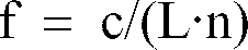

wobei Uπ eine konstante Spannung ist. Durch Anlegen einer konstanten Vorspannung Uv im Bereich 0 < Uv < Uπ wird erreicht, daß der optische Modulator MOD als Dämpfungsglied arbeitet und der modengekoppelte Faserringlaser LAS somit in einem gedrosselten Betrieb arbeitet. Ein Teil des Signallichts wird über die asymmetrischen Faserkoppler FC1, FC2 dem optischen Filter FIL1 zugeführt. Das optische Filter FIL1 filtert die Lichtkomponente mit der gewünschten Pulsfolgefrequenz aus dem Teil des Signallichts heraus und führt das so gewonnene optische Signal dem optisch/elektrischen Wandler O/E zu. Der optisch/elektrische Wandler O/E wandelt das optische
Signal in ein elektrisches Signal, welches als Eingangssignal für den Detektor DET dient. Die Amplitude des elektrischen Signals bestimmt die Detektorausgangsspannung, die die Steuerspannung U des optischen Modulators MOD darstellt. Liegt kein elektrisches Signal am Detektor DET an, so hat die Steuerspannung U den Wert der Vorspannung Uv. Bei maximaler Amplitude des elektrischen Signals am Detektor hat die Steuerspannung U den Wert Null, d.h. die Transmission T hat den Wert Eins und der optische Modulator MOD fungiert nur noch als Durchschalteglied. Der Wertebereich der Steuerspannung U ist demnach gegeben durch 0 ≦ U ≦ Uv . Durch die Rückkoppelschleife RS wird erreicht, daß sich Signallicht mit ausschließlich der gewünschten Pulsfolgefrequenz im Ringresonator RES ausbildet. Im Mittel ist die Amplitude der sich ausbildenden Lichtkomponenten nahezu konstant. Bedingt durch eine statistische Verteilung bilden sich kurzzeitig Zustände aus, bei denen die Amplitude einzelner Lichtkomponenten höher als die Amplitude der restlichen Lichtkomponenten ist. Tritt der Zustand, bei dem die Amplitude der Lichtkomponente mit der gewünschten Pulsfolgefrequenz hoch gegenüber der Amplitude der restlichen Lichtkomponenten ist, auf, so wird über die Rückkoppelschleife RS die Transmission T im optischen Modulator MOD erhöht. Die erhöhte Transmission T führt zu einem weiteren Anstieg der Amplitude der Lichtkomponente mit der gewünschten Pulsfolgefrequenz, welche wiederum zu einer erhöhten Transmission T führt. Ein stabiler Zustand ist erreicht, wenn der Transmissionswert T = 1 ist und im Ringresonator RES ausschließlich optische Pulse mit der gewünschten Pulsfolgefrequenz zirkulieren. Mit einem einstellbaren optischen Filter FIL1 kann der modengekoppelte Faserringlaser LAS somit zur Erzeugung optischer Pulse, deren Pulsfolgefrequenz bedingt einstellbar ist, verwendet werden. Die bedingte Einstellbarkeit der Pulsfolgefrequenz resultiert aus der Tatsache, daß die Pulsfolgefrequenz einem ganzzahligen Vielfachen der Umlauffrequenz f des Lichts im Ringresonator RES entsprechen muß. - Fig. 2 zeigt nun einen erfindungsgemäßen passiv modengekoppelten Faserringlaser mit einem elektrischen Filter. Der passiv modengekoppelte Faserringlaser LAS ist wie der anhand von Fig. 1 beschriebene Laser ein Faserringlaser mit Rückkoppelschleife. Bis auf die Anordnung des zweiten Faserkopplers FC2 und die Elemente der Rückkoppelschleife RS sind der passiv modengekoppelte Faserringlaser LAS und der anhand von Fig. 1 beschriebene Laser identisch. Die Rückkoppelschleife RS beinhaltet einen optisch/elektrischen Wandler O/E, ein elektrisches Filter FIL2 und einen Detektor DET. Der zweite Faserkoppler FC2 zur Erzeugung des Ausgangs OUT des modengekoppelten Faserringlasers LAS ist anstatt in die Rückkoppelschleife RS (wie im anhand von Fig. 1 beschriebenen Laser) in den Ringresonator RES eingefügt.
- Das elektrische Filter FIL2 ist z.B. ein Bandpaßfilter. Es dient dazu, aus einem elektrischen Signal die gewünschte Pulsfolgefrequenz herauszufiltern.
- Nach dem Einschalten des passiv modengekoppelten Faserringlasers LAS bildet sich im Ringresonator RES Signallicht mit mehreren Pulsfolgefrequenzen durch stimulierte Emissionen in der Erbium dotierten Faser aus. Das Signallicht hat somit mehrere Lichtkomponenten mit unterschiedlichen Pulsfolgefrequenzen. Dabei wird der optische Modulator MOD (Mach-Zehnder-Modulator) mit einer konstanten Vorspannung Uv angesteuert. Ein Teil des Signallichts wird über den asymmetrischen Faserkoppler FC1 dem optisch/elektrischen Wandler O/E zugeführt. Der optische/elektrische Wandler O/E wandelt das optische Signal in ein elektrisches Signal, welches als Eingangssignal für das elektrische Filter FIL2 dient. Das elektrische Signal hat mehrere elektrische Signalkomponenten mit unterschiedlichen Pulsfolgefrequenzen. Das elektrische Filter filtert eine elektrische Signalkomponente aus dem elektrischen Signal aus und führt das so gewonnene elektrische Wechselspannungssignal dem Detektor zu. Die Amplitude des elektrischen Wechselspannungssignals bestimmt die Detektorausgangsspannung, die die Steuerspannung U des optischen Modulators MOD darstellt. Liegt kein elektrisches Signal am Detektor DET an, so hat die Steuerspannung U den Wert der Vorspannung Uv. Bei maximaler Amplitude des elektrischen Signals am Detektor hat die Steuerspannung U den Wert Null, d.h. die Transmission T hat den Wert Eins und der optische Modulator MOD fungiert nur noch als Durchschalteglied. Der Wertebereich der Steuerspannung U ist demnach gegeben durch 0 ≦ U ≦ Uv. Durch die Rückkoppelschleife RS wird erreicht, daß sich Signallicht mit ausschließlich der gewünschten Pulsfolgefrequenz im Ringresonator RES ausbildet. Im Mittel ist die Amplitude der sich ausbildenden elektrischen Signalkomponenten nahezu konstant. Bedingt durch eine statistische Verteilung bilden sich kurzzeitig Zustände aus, bei denen die Amplitude einzelner elektrischer Signalkomponenten höher als die Amplitude der restlichen elektrischen Signalkomponenten ist. Tritt der Zustand, bei dem die Amplitude der elektrischen Signalkomponente mit der gewünschten Pulsfolgefrequenz hoch gegenüber der Amplitude der restlichen elektrischen Signalkomponenten ist, auf, so wird über die Rückkoppelschleife RS die Transmission T im optischen Modulator MOD erhöht. Die erhöhte Transmission T führt zu einem weiteren Anstieg der Amplitude der elektrischen Signalkomponente mit der gewünschten Pulsfolgefrequenz, welche wiederum zu einer erhöhten Transmission T führt. Ein stabiler Zustand ist erreicht, wenn der Transmissionswert T = 1 ist und im Ringresonator RES ausschließlich optische Pulse mit der gewünschten Pulsfolgefrequenz zirkulieren. Mit einem einstellbaren elektrischen Filter FIL2 kann der passiv modengekoppelte Faserringlaser LAS somit zur Erzeugung optischer Pulse, deren Pulsfolgefrequenz bedingt einstellbar ist, verwendet werden. Die bedingte Einstellbarkeit der Pulsfolgefrequenz resultiert aus der Tatsache, daß die Pulsfolgefrequenz einem ganzzahligen Vielfachen der Umlauffrequenz f des Lichts im Ringresonator RES entsprechen muß.
- Bei den Ausführungsbeispielen sind die verwendeten Fasern aus Stabilitätsgründen vorteilhafterweise polarisationserhaltende Einmodenfasern. Die polarisationserhaltenden Einmodenfasern verhindern eventuell durch Polarisation bedingte Interferenzerscheinungen, die die Funktionsweise des modengekoppelten Faserringlasers LAS beeinträchtigen könnten.
- Vorteilhafterweise kann in beiden Ausführungsbeispielen zur Stabilisierung des passiv modengekoppelten Faserringlasers LAS jeweils ein optisches Filter in den Resonatorkreis eingefügt werden, z.B. zwischen optischem Isolator ISO und optischem Modulator MOD. Dieses optische Filter sollte breitbandig und für Signallicht in einem, z.B. 2-3 nm breiten Fenster durchlässig sein. So könnte das optische Filter z.B. für Signallicht der Wellenlänge 1530 nm +/- 1,5 nm durchlässig sein.
- Im ersten Ausführungsbeispiel kann der Pegeldetektor im Detektor DET eingespart werden, wenn man als optisch/elektrischen Wandler O/E eine "langsame" Photodiode einsetzt, d.h. eine Photodiode, deren Empfindlichkeit weit geringer als die Pulsfolgefrequenz ist. Auf diese Weise wird die Pegelmessung bereits durch die Photodiode durchgeführt. Das Ausgangssignal der Photodiode braucht dann nur noch an den Aussteuerbereich des optischen Modulators MOD angepaßt werden.
- In den Ausführungsbeispielen ist ein passiv modengekoppelter Faserringlaser LAS mit einer Erbium dotierten Faser ER als laseraktives Medium beschrieben. Anstelle der Erbium dotierten Faser kann auch eine mit einem anderen Element aus der Gruppe der seltenen Erden dotierte Faser ER als laseraktives Medium verwendet werden.
- Ferner sind in den Ausführungsbeispielen im wesentlichen nur die für das Verständnis erforderlichen Teile und Baugruppen des passiv modengekoppelten Faserringlasers LAS erwähnt. Auf weitere Teile und Baugruppen, wie z.B. zusätzliche optische Isolatoren, Polarisatoren, optische Filter, optische Dämpfer oder Synchronisationseinrichtungen, deren Verwendung, Anordnung, Vorteile oder gar Notwendigkeit dem Fachmann z.B. aus der Druckschrift Electronic Letters 24th October 1991, Vol. 27, No. 22 bekannt sind, wurde in der Beschreibung nicht näher eingegangen.
Claims (10)
- Modengekoppelter Faserringlaser (LAS) zur Erzeugung optischer Pulse, mit einem laseraktiven Medium (ER), mit einem Ringresonator (RES), mit einer Pumplichtquelle (PUMP), mit einem optischen Modulator (MOD) und mit einer Auskoppelvorrichtung (FC1) zum Auskoppeln von Signallicht,
dadurch gekennzeichnet, daß der optische Modulator (MOD) durch ein Steuersignal angesteuert werden kann und das Steuersignal über eine Rückkoppelschleife (RS) aus einem Teil des Signallichts gewonnen werden kann. - Modengekoppelter Faserringlaser (LAS) nach Anspruch 1, dadurch gekennzeichnet, daß in die Rückkoppelschleife (RS) ein optisches Filter (FIL1) eingefügt ist.
- Modengekoppelter Faserringlaser (LAS) nach Anspruch 1, dadurch gekennzeichnet, daß in die Rückkoppelschleife (RS) ein elektrisches Filter (FIL2) eingefügt ist.
- Modengekoppelter Faserringlaser (LAS) nach Anspruch 2 oder 3, dadurch gekennzeichnet, daß die durch das Filter (FIL1, 2) herausfilterbare Pulsfolgefrequenz einstellbar ist.
- Modengekoppelter Faserringlaser (LAS) nach Anspruch 1, dadurch gekennzeichnet, daß der optische Modulator (MOD) durch ein elektrisches Steuersignal ansteuerbar ist, und daß in die Rückkoppelschleife (RS) ein optisch/elektrischer Wandler (O/E) eingefügt ist.
- Modengekoppelter Faserringlaser (LAS) nach Anspruch 5, dadurch gekennzeichnet, daß das elektrische Steuersignal eine Gleichspannung ist.
- Modengekoppelter Faserringlaser (LAS) nach Anspruch 1, dadurch gekennzeichnet, daß in den Ringresonator (RES) ein optisches Filter eingefügt ist.
- Modengekoppelter Faserringlaser (LAS) nach Anspruch 1, dadurch gekennzeichnet, daß das laseraktive Medium (ER) eine mit einem Element aus der Gruppe der seltenen Erden dotierte Faser ist.
- Modengekoppelter Faserringlaser (LAS) nach Anspruch 1, dadurch gekennzeichnet, daß die verwendeten Fasern polarisationserhaltende Einmodenfasern sind.
- Modengekoppelter Faserringlaser (LAS) nach Anspruch 1, dadurch gekennzeichnet, daß in den Ringresonator (RES) ein oder mehrere optische Isolatoren (ISO) eingefügt sind.
Applications Claiming Priority (2)
| Application Number | Priority Date | Filing Date | Title |
|---|---|---|---|
| DE4425809 | 1994-07-21 | ||
| DE4425809A DE4425809A1 (de) | 1994-07-21 | 1994-07-21 | Modengekoppelter Faserringlaser |
Publications (3)
| Publication Number | Publication Date |
|---|---|
| EP0693809A2 true EP0693809A2 (de) | 1996-01-24 |
| EP0693809A3 EP0693809A3 (de) | 1997-10-15 |
| EP0693809B1 EP0693809B1 (de) | 1999-10-06 |
Family
ID=6523760
Family Applications (1)
| Application Number | Title | Priority Date | Filing Date |
|---|---|---|---|
| EP95111416A Expired - Lifetime EP0693809B1 (de) | 1994-07-21 | 1995-07-20 | Modengekoppelter Faserringlaser |
Country Status (5)
| Country | Link |
|---|---|
| US (1) | US5546414A (de) |
| EP (1) | EP0693809B1 (de) |
| JP (1) | JPH08172228A (de) |
| CA (1) | CA2152874A1 (de) |
| DE (2) | DE4425809A1 (de) |
Cited By (3)
| Publication number | Priority date | Publication date | Assignee | Title |
|---|---|---|---|---|
| DE19626128A1 (de) * | 1996-06-28 | 1998-01-08 | Sel Alcatel Ag | Sendeeinrichtung, Sendeeinheit und optisches Übertragungssystem zur optischen Übertragung analoger elektrischer Signale |
| WO2009143897A1 (en) | 2008-05-30 | 2009-12-03 | Telefonaktiebolaget Lm Ericsson (Publ) | Apparatus and method for generating optical pulses |
| CN103500921A (zh) * | 2013-10-22 | 2014-01-08 | 山东大学 | 一种低重频高稳定亚纳秒脉冲绿激光产生装置 |
Families Citing this family (22)
| Publication number | Priority date | Publication date | Assignee | Title |
|---|---|---|---|---|
| JPH08149087A (ja) * | 1994-11-16 | 1996-06-07 | Furukawa Electric Co Ltd:The | 光通信方式 |
| DE4441133A1 (de) * | 1994-11-21 | 1996-05-23 | Sel Alcatel Ag | Modengekoppelter Faserlaser |
| JP3234429B2 (ja) * | 1995-01-17 | 2001-12-04 | 日本電信電話株式会社 | モード同期レーザの動作安定化装置 |
| US5623508A (en) * | 1996-02-12 | 1997-04-22 | Lucent Technologies Inc. | Article comprising a counter-pumped optical fiber raman amplifier |
| DE19730830A1 (de) * | 1997-07-18 | 1999-01-21 | Alsthom Cge Alcatel | Laser zur Erzeugung eines Wellenkamms |
| US6151336A (en) * | 1998-02-11 | 2000-11-21 | Sorrento Networks, Inc. | Time division multiplexing expansion subsystem |
| US6400478B1 (en) | 1998-04-02 | 2002-06-04 | Sorrento Networks, Inc. | Wavelength-division-multiplexed optical transmission system with expanded bidirectional transmission capacity over a single fiber |
| KR100269040B1 (ko) * | 1998-04-28 | 2000-10-16 | 서원석 | 파장이동 레이저 광원 및 파장이동 레이저 광 생성방법 |
| US6298103B1 (en) | 1998-06-16 | 2001-10-02 | Sorrento Networks Corporation | Flexible clock and data recovery module for a DWDM optical communication system with multiple clock rates |
| US7106917B2 (en) | 1998-11-13 | 2006-09-12 | Xponent Photonics Inc | Resonant optical modulators |
| KR100280822B1 (ko) | 1998-12-03 | 2001-03-02 | 정선종 | 광섬유 모드 록킹 레이저 |
| US6510167B1 (en) | 1999-09-22 | 2003-01-21 | Science & Technology Corporation @Unm | Method for actively modelocking an all-fiber laser |
| US7065302B1 (en) | 2000-09-15 | 2006-06-20 | Lockheed Martin Corporation | High efficiency optical feedback modulator and method of operation |
| WO2002050575A2 (en) * | 2000-12-21 | 2002-06-27 | Cquint Communications Corporation | Resonant optical modulators |
| US6690687B2 (en) | 2001-01-02 | 2004-02-10 | Spectrasensors, Inc. | Tunable semiconductor laser having cavity with ring resonator mirror and mach-zehnder interferometer |
| US20020131100A1 (en) * | 2001-03-16 | 2002-09-19 | Myers Michael H. | Method for photonic wavelength error detection |
| US6407846B1 (en) | 2001-03-16 | 2002-06-18 | All Optical Networks, Inc. | Photonic wavelength shifting method |
| US20020131125A1 (en) * | 2001-03-16 | 2002-09-19 | Myers Michael H. | Replicated-spectrum photonic transceiving |
| JP2003035603A (ja) * | 2001-07-18 | 2003-02-07 | Ando Electric Co Ltd | 光サンプリング波形観測装置 |
| JP3751547B2 (ja) * | 2001-08-28 | 2006-03-01 | 横河電機株式会社 | 光サンプリング波形観測装置 |
| JP2013093349A (ja) * | 2011-10-24 | 2013-05-16 | Toshiba Corp | 磁気記憶素子 |
| CN114498259B (zh) * | 2021-12-22 | 2024-05-03 | 西安空间无线电技术研究所 | 一种自再生锁模光电振荡器 |
Family Cites Families (5)
| Publication number | Priority date | Publication date | Assignee | Title |
|---|---|---|---|---|
| US4530603A (en) * | 1982-09-29 | 1985-07-23 | The Board Of Trustees Of Leland Stanford Jr. Univ. | Stabilized fiber optic sensor |
| US5216681A (en) * | 1991-08-05 | 1993-06-01 | Trw Inc. | Highly-efficient solid-state blue laser |
| US5212711A (en) * | 1992-02-18 | 1993-05-18 | At&T Bell Laboratories | Harmonically mode-locked laser |
| IT1272640B (it) * | 1993-09-16 | 1997-06-26 | Pirelli Cavi Spa | Generatore laser a fibra ottica a concatenamento modale passivo a commutazione non lineare di polarizzazione |
| US5359612A (en) * | 1993-09-29 | 1994-10-25 | The United States Of America As Represented By The Secretary Of The Navy | High repetition rate, mode locked, figure eight laser with extracavity feedback |
-
1994
- 1994-07-21 DE DE4425809A patent/DE4425809A1/de not_active Withdrawn
-
1995
- 1995-06-07 US US08/483,545 patent/US5546414A/en not_active Expired - Fee Related
- 1995-06-28 CA CA002152874A patent/CA2152874A1/en not_active Abandoned
- 1995-07-20 EP EP95111416A patent/EP0693809B1/de not_active Expired - Lifetime
- 1995-07-20 JP JP7184290A patent/JPH08172228A/ja active Pending
- 1995-07-20 DE DE59506975T patent/DE59506975D1/de not_active Expired - Fee Related
Non-Patent Citations (2)
| Title |
|---|
| ELECTRONIC LETTERS, vol. 27, no. 22, 24 October 1991 (1991-10-24) |
| IEEE JOURNAL OF QUANTUM ELECTRONICS, vol. 27, no. 3, March 1991 (1991-03-01), pages 654 - 667 |
Cited By (3)
| Publication number | Priority date | Publication date | Assignee | Title |
|---|---|---|---|---|
| DE19626128A1 (de) * | 1996-06-28 | 1998-01-08 | Sel Alcatel Ag | Sendeeinrichtung, Sendeeinheit und optisches Übertragungssystem zur optischen Übertragung analoger elektrischer Signale |
| WO2009143897A1 (en) | 2008-05-30 | 2009-12-03 | Telefonaktiebolaget Lm Ericsson (Publ) | Apparatus and method for generating optical pulses |
| CN103500921A (zh) * | 2013-10-22 | 2014-01-08 | 山东大学 | 一种低重频高稳定亚纳秒脉冲绿激光产生装置 |
Also Published As
| Publication number | Publication date |
|---|---|
| EP0693809B1 (de) | 1999-10-06 |
| US5546414A (en) | 1996-08-13 |
| EP0693809A3 (de) | 1997-10-15 |
| JPH08172228A (ja) | 1996-07-02 |
| DE59506975D1 (de) | 1999-11-11 |
| DE4425809A1 (de) | 1996-01-25 |
| CA2152874A1 (en) | 1996-01-22 |
Similar Documents
| Publication | Publication Date | Title |
|---|---|---|
| EP0693809B1 (de) | Modengekoppelter Faserringlaser | |
| DE69033859T2 (de) | Optischer Verstärker und optisches Übertragungssystem damit | |
| DE69510438T2 (de) | Optischer Hochleistungssender mit hochgesättigtem Verstärker zur Unterdrückung der Restamplitudenmodulation | |
| DE69632720T2 (de) | Mehrfrequenzphasenmodulation für lichtwellenübertragungssystem | |
| DE69233151T2 (de) | Polarisationsmultiplexierung mit solitons | |
| DE69028469T2 (de) | Verteilte Verstärkung für Lichtwellenübertragungssystem | |
| DE69108349T2 (de) | Optische Verstärker. | |
| DE69217426T2 (de) | Soliton faseroptisches Übertragungssystem | |
| DE69429416T2 (de) | Vollständig optisches Flip-Flop | |
| DE4234599A1 (de) | Optischer Sender | |
| DE69631817T2 (de) | Sender für modulierte und depolarisierte optische Signale | |
| DE19512160A1 (de) | Verfahren und Gerät zur Erzeugung ultrakurzer Impulse mit hoher Energie | |
| EP0554736A2 (de) | Digitales optisches Nachrichtenübertragungssystem mit einem bei der Betriebswellenlänge dispersionsbehafteten Lichtwellenleiter | |
| DE69429418T2 (de) | Rein optischer Inverter | |
| EP0568897B1 (de) | Faseroptischer Verstärker mit rückwirkungsunempfindlichem Pumplaser | |
| DE69114282T2 (de) | Optischer signalregenerator und optisches übertragungssystem, das diesen benutzt. | |
| DE69223577T2 (de) | Optisches Regenerator-Relaissystem | |
| EP0607868B1 (de) | Optische Sendeeinrichtung und Nachichtenübertragungssystem | |
| DE69022151T2 (de) | Halbleiterlaserverstärkereinheit hoher Verstärkung. | |
| EP0428016A2 (de) | Modulationsstromregelung für Laserdioden | |
| DE69126318T2 (de) | Optische taktwiedergewinnung | |
| DE4014034A1 (de) | Optischer verstaerker | |
| EP0673092B1 (de) | Optisch gepumpter bistabiler Laser | |
| DE3856077T2 (de) | Optischer Verstärker | |
| DE4005867A1 (de) | Faseroptischer verstaerker |
Legal Events
| Date | Code | Title | Description |
|---|---|---|---|
| PUAI | Public reference made under article 153(3) epc to a published international application that has entered the european phase |
Free format text: ORIGINAL CODE: 0009012 |
|
| AK | Designated contracting states |
Kind code of ref document: A2 Designated state(s): CH DE ES FR GB IT LI SE |
|
| PUAL | Search report despatched |
Free format text: ORIGINAL CODE: 0009013 |
|
| AK | Designated contracting states |
Kind code of ref document: A3 Designated state(s): CH DE ES FR GB IT LI SE |
|
| 17P | Request for examination filed |
Effective date: 19971129 |
|
| GRAG | Despatch of communication of intention to grant |
Free format text: ORIGINAL CODE: EPIDOS AGRA |
|
| 17Q | First examination report despatched |
Effective date: 19981209 |
|
| GRAG | Despatch of communication of intention to grant |
Free format text: ORIGINAL CODE: EPIDOS AGRA |
|
| GRAH | Despatch of communication of intention to grant a patent |
Free format text: ORIGINAL CODE: EPIDOS IGRA |
|
| GRAH | Despatch of communication of intention to grant a patent |
Free format text: ORIGINAL CODE: EPIDOS IGRA |
|
| GRAA | (expected) grant |
Free format text: ORIGINAL CODE: 0009210 |
|
| RAP1 | Party data changed (applicant data changed or rights of an application transferred) |
Owner name: ALCATEL |
|
| AK | Designated contracting states |
Kind code of ref document: B1 Designated state(s): CH DE ES FR GB IT LI SE |
|
| PG25 | Lapsed in a contracting state [announced via postgrant information from national office to epo] |
Ref country code: ES Free format text: THE PATENT HAS BEEN ANNULLED BY A DECISION OF A NATIONAL AUTHORITY Effective date: 19991006 |
|
| RAP1 | Party data changed (applicant data changed or rights of an application transferred) |
Owner name: ALCATEL |
|
| ITF | It: translation for a ep patent filed | ||
| REG | Reference to a national code |
Ref country code: CH Ref legal event code: EP |
|
| REG | Reference to a national code |
Ref country code: CH Ref legal event code: NV Representative=s name: CABINET ROLAND NITHARDT CONSEILS EN PROPRIETE INDU |
|
| REF | Corresponds to: |
Ref document number: 59506975 Country of ref document: DE Date of ref document: 19991111 |
|
| GBT | Gb: translation of ep patent filed (gb section 77(6)(a)/1977) |
Effective date: 19991108 |
|
| ET | Fr: translation filed | ||
| PG25 | Lapsed in a contracting state [announced via postgrant information from national office to epo] |
Ref country code: LI Free format text: LAPSE BECAUSE OF NON-PAYMENT OF DUE FEES Effective date: 20000731 Ref country code: CH Free format text: LAPSE BECAUSE OF NON-PAYMENT OF DUE FEES Effective date: 20000731 |
|
| PLBE | No opposition filed within time limit |
Free format text: ORIGINAL CODE: 0009261 |
|
| 26N | No opposition filed | ||
| REG | Reference to a national code |
Ref country code: CH Ref legal event code: PL |
|
| REG | Reference to a national code |
Ref country code: GB Ref legal event code: IF02 |
|
| PGFP | Annual fee paid to national office [announced via postgrant information from national office to epo] |
Ref country code: SE Payment date: 20020625 Year of fee payment: 8 |
|
| PGFP | Annual fee paid to national office [announced via postgrant information from national office to epo] |
Ref country code: GB Payment date: 20020628 Year of fee payment: 8 |
|
| PGFP | Annual fee paid to national office [announced via postgrant information from national office to epo] |
Ref country code: FR Payment date: 20020711 Year of fee payment: 8 Ref country code: DE Payment date: 20020711 Year of fee payment: 8 |
|
| PG25 | Lapsed in a contracting state [announced via postgrant information from national office to epo] |
Ref country code: GB Free format text: LAPSE BECAUSE OF NON-PAYMENT OF DUE FEES Effective date: 20030720 |
|
| PG25 | Lapsed in a contracting state [announced via postgrant information from national office to epo] |
Ref country code: SE Free format text: LAPSE BECAUSE OF NON-PAYMENT OF DUE FEES Effective date: 20030721 |
|
| PG25 | Lapsed in a contracting state [announced via postgrant information from national office to epo] |
Ref country code: DE Free format text: LAPSE BECAUSE OF NON-PAYMENT OF DUE FEES Effective date: 20040203 |
|
| EUG | Se: european patent has lapsed | ||
| GBPC | Gb: european patent ceased through non-payment of renewal fee |
Effective date: 20030720 |
|
| PG25 | Lapsed in a contracting state [announced via postgrant information from national office to epo] |
Ref country code: FR Free format text: LAPSE BECAUSE OF NON-PAYMENT OF DUE FEES Effective date: 20040331 |
|
| REG | Reference to a national code |
Ref country code: FR Ref legal event code: ST |
|
| PG25 | Lapsed in a contracting state [announced via postgrant information from national office to epo] |
Ref country code: IT Free format text: LAPSE BECAUSE OF NON-PAYMENT OF DUE FEES Effective date: 20050720 |