EP0694203B1 - Moteur electrique, procedes de commande et de montage - Google Patents
Moteur electrique, procedes de commande et de montage Download PDFInfo
- Publication number
- EP0694203B1 EP0694203B1 EP92911720A EP92911720A EP0694203B1 EP 0694203 B1 EP0694203 B1 EP 0694203B1 EP 92911720 A EP92911720 A EP 92911720A EP 92911720 A EP92911720 A EP 92911720A EP 0694203 B1 EP0694203 B1 EP 0694203B1
- Authority
- EP
- European Patent Office
- Prior art keywords
- stator
- coil
- electric motor
- motor
- assembly
- Prior art date
- Legal status (The legal status is an assumption and is not a legal conclusion. Google has not performed a legal analysis and makes no representation as to the accuracy of the status listed.)
- Expired - Lifetime
Links
- 238000000034 method Methods 0.000 title claims description 15
- 230000005291 magnetic effect Effects 0.000 claims description 32
- 239000000758 substrate Substances 0.000 claims description 28
- 230000004907 flux Effects 0.000 claims description 16
- 230000004044 response Effects 0.000 claims description 14
- 239000004020 conductor Substances 0.000 claims description 11
- 230000035699 permeability Effects 0.000 claims description 6
- 238000004804 winding Methods 0.000 claims description 6
- 238000012545 processing Methods 0.000 claims description 5
- 230000000712 assembly Effects 0.000 claims description 4
- 238000000429 assembly Methods 0.000 claims description 4
- 238000003475 lamination Methods 0.000 claims description 3
- 239000000463 material Substances 0.000 claims description 2
- 239000011810 insulating material Substances 0.000 claims 5
- 230000006870 function Effects 0.000 description 14
- 238000010586 diagram Methods 0.000 description 10
- 238000004891 communication Methods 0.000 description 8
- 238000010276 construction Methods 0.000 description 6
- 230000036961 partial effect Effects 0.000 description 5
- 230000002829 reductive effect Effects 0.000 description 5
- 208000019300 CLIPPERS Diseases 0.000 description 4
- 208000021930 chronic lymphocytic inflammation with pontine perivascular enhancement responsive to steroids Diseases 0.000 description 4
- 230000005389 magnetism Effects 0.000 description 4
- 230000005294 ferromagnetic effect Effects 0.000 description 3
- 239000000446 fuel Substances 0.000 description 3
- 230000007246 mechanism Effects 0.000 description 3
- 239000004065 semiconductor Substances 0.000 description 3
- 229910000679 solder Inorganic materials 0.000 description 3
- 229920004943 Delrin® Polymers 0.000 description 2
- 229910001209 Low-carbon steel Inorganic materials 0.000 description 2
- 230000008901 benefit Effects 0.000 description 2
- 239000000919 ceramic Substances 0.000 description 2
- 230000008859 change Effects 0.000 description 2
- 238000013461 design Methods 0.000 description 2
- 239000011521 glass Substances 0.000 description 2
- 238000004519 manufacturing process Methods 0.000 description 2
- 230000008569 process Effects 0.000 description 2
- 230000020347 spindle assembly Effects 0.000 description 2
- 241000238876 Acari Species 0.000 description 1
- 229910000975 Carbon steel Inorganic materials 0.000 description 1
- RYGMFSIKBFXOCR-UHFFFAOYSA-N Copper Chemical compound [Cu] RYGMFSIKBFXOCR-UHFFFAOYSA-N 0.000 description 1
- 241000233805 Phoenix Species 0.000 description 1
- 229910000831 Steel Inorganic materials 0.000 description 1
- 230000002411 adverse Effects 0.000 description 1
- 239000010962 carbon steel Substances 0.000 description 1
- 238000011217 control strategy Methods 0.000 description 1
- 238000013524 data verification Methods 0.000 description 1
- 238000001514 detection method Methods 0.000 description 1
- 230000006866 deterioration Effects 0.000 description 1
- 230000009977 dual effect Effects 0.000 description 1
- 239000000428 dust Substances 0.000 description 1
- 230000005672 electromagnetic field Effects 0.000 description 1
- 239000003302 ferromagnetic material Substances 0.000 description 1
- 230000006872 improvement Effects 0.000 description 1
- 238000004377 microelectronic Methods 0.000 description 1
- 230000009467 reduction Effects 0.000 description 1
- 238000011160 research Methods 0.000 description 1
- 230000000452 restraining effect Effects 0.000 description 1
- 230000000717 retained effect Effects 0.000 description 1
- 239000010935 stainless steel Substances 0.000 description 1
- 229910001220 stainless steel Inorganic materials 0.000 description 1
- 239000010959 steel Substances 0.000 description 1
Images





Classifications
-
- H—ELECTRICITY
- H01—ELECTRIC ELEMENTS
- H01F—MAGNETS; INDUCTANCES; TRANSFORMERS; SELECTION OF MATERIALS FOR THEIR MAGNETIC PROPERTIES
- H01F7/00—Magnets
- H01F7/06—Electromagnets; Actuators including electromagnets
- H01F7/08—Electromagnets; Actuators including electromagnets with armatures
- H01F7/14—Pivoting armatures
- H01F7/145—Rotary electromagnets with variable gap
-
- H—ELECTRICITY
- H02—GENERATION; CONVERSION OR DISTRIBUTION OF ELECTRIC POWER
- H02K—DYNAMO-ELECTRIC MACHINES
- H02K11/00—Structural association of dynamo-electric machines with electric components or with devices for shielding, monitoring or protection
- H02K11/01—Structural association of dynamo-electric machines with electric components or with devices for shielding, monitoring or protection for shielding from electromagnetic fields, i.e. structural association with shields
- H02K11/014—Shields associated with stationary parts, e.g. stator cores
- H02K11/0141—Shields associated with casings, enclosures or brackets
-
- H—ELECTRICITY
- H02—GENERATION; CONVERSION OR DISTRIBUTION OF ELECTRIC POWER
- H02K—DYNAMO-ELECTRIC MACHINES
- H02K24/00—Machines adapted for the instantaneous transmission or reception of the angular displacement of rotating parts, e.g. synchro, selsyn
-
- H—ELECTRICITY
- H02—GENERATION; CONVERSION OR DISTRIBUTION OF ELECTRIC POWER
- H02K—DYNAMO-ELECTRIC MACHINES
- H02K7/00—Arrangements for handling mechanical energy structurally associated with dynamo-electric machines, e.g. structural association with mechanical driving motors or auxiliary dynamo-electric machines
- H02K7/10—Structural association with clutches, brakes, gears, pulleys or mechanical starters
- H02K7/102—Structural association with clutches, brakes, gears, pulleys or mechanical starters with friction brakes
-
- H—ELECTRICITY
- H02—GENERATION; CONVERSION OR DISTRIBUTION OF ELECTRIC POWER
- H02K—DYNAMO-ELECTRIC MACHINES
- H02K7/00—Arrangements for handling mechanical energy structurally associated with dynamo-electric machines, e.g. structural association with mechanical driving motors or auxiliary dynamo-electric machines
- H02K7/10—Structural association with clutches, brakes, gears, pulleys or mechanical starters
- H02K7/12—Structural association with clutches, brakes, gears, pulleys or mechanical starters with auxiliary limited movement of stators, rotors or core parts, e.g. rotors axially movable for the purpose of clutching or braking
- H02K7/125—Structural association with clutches, brakes, gears, pulleys or mechanical starters with auxiliary limited movement of stators, rotors or core parts, e.g. rotors axially movable for the purpose of clutching or braking magnetically influenced
-
- Y—GENERAL TAGGING OF NEW TECHNOLOGICAL DEVELOPMENTS; GENERAL TAGGING OF CROSS-SECTIONAL TECHNOLOGIES SPANNING OVER SEVERAL SECTIONS OF THE IPC; TECHNICAL SUBJECTS COVERED BY FORMER USPC CROSS-REFERENCE ART COLLECTIONS [XRACs] AND DIGESTS
- Y10—TECHNICAL SUBJECTS COVERED BY FORMER USPC
- Y10T—TECHNICAL SUBJECTS COVERED BY FORMER US CLASSIFICATION
- Y10T29/00—Metal working
- Y10T29/49—Method of mechanical manufacture
- Y10T29/49002—Electrical device making
- Y10T29/49009—Dynamoelectric machine
- Y10T29/49011—Commutator or slip ring assembly
Definitions
- the present application is related to electric motors, a controller therefor and methods for controlling and assembling the same and, in particular, to miniature electric motors and a controller therefor and methods for controlling and assembling the same.
- Miniature electric motors that can be rotated between fixed angles and held stationary at those fixed angles for a specified period of time are finding a wide variety of applications such as for driving needle indicators in meters and gauges. For such motors to find wide application they must have high performance, be relatively low cost, and have a compact construction.
- a stepper motor uses electromagnetic detents to maintain a rotor at a desired location. Electrical energy is added to cause the rotor to move past a magnetic hill. When the motor is deenergized, the rotor will settle and be maintained within a magnetic valley. A stepper motor is therefore designed with these magnetic valleys located at the desired stopping positions.
- stepper motors Another drawback of stepper motors is that as the motor settles in a magnetic valley, the motor shaft may vibrate before coming to rest at the desired location. This vibration could cause damage or excess wear to the motor or to a payload.
- a micro-stepper motor offers an improvement over the stepper motor in that it allows a shaft to be held at an indefinite number of positions.
- the micro-stepper motor operates by applying electrically orthogonal signals to spatially orthogonal poles of a motor. By changing the ratio of magnitude of the signals applied, the motor can be moved to and held at any desired location. In order to hold the rotor at a desired location, however, electrical energy must be applied constantly. As a result, the performance of micro-stepper motors has been limited by the requirement of a corresponding increase in applied electrical energy for greater restraining torques.
- the gauge mechanism consists of surface mount coils and a permanent magnet spindle assembly. Attached to the spindle can be a dial pointer or other indicating device.
- the coils have a high permeability core and are wound with insulated copper wire for the coil.
- the rotational position of the spindle assembly permanent magnet is controlled by the amount and direction of electrical current in the surface mount coils.
- the mechanism is held in place by a bottom self-lubricating bearing and an upper bearing bracket.
- the upper bearing bracket also serves as a flux-containing package.
- US-A-3970980 discloses a rotary actuator comprising a cylindrical housing in which are cylindrically curved permanently magnetized poles spaced apart at their ends and surrounding a fixed armature.
- the armature has magnetic arms angularly disposed with respect to each other which define fixed poles. Coils wound on the fixed poles generate magnetic fields when energised, to drive the rotor.
- US-A-4554491 discloses a DC brushless motor in which the stator has a central annular portion defining a central aperture, a plurality of winding core members extending radially from the central annular portion and a plurality of intermediate core members which extend radially from the central annular portion and are positioned intermediate the winding core portions.
- a control circuit simultaneously excites all of the winding core portions and electrically reverses the exciting current as a function of the rotational position of the rotor.
- a further object of the present invention is to provide methods for controlling and assembling such electric motors.
- an electric motor for rotating a load to a desired angular position in response to a sensor signal
- the electric motor including a stator assembly including a stator having a plurality of lobes, the stator including at least one coil wound about at least one of the plurality of lobes, each coil having a pair of input leads;
- a method for controlling an electric motor for driving a load having a stator assembly and a rotor assembly for rotating relative to the stator assembly, the method characterized by the steps of:
- a method of assembling a miniature motor for accurately rotating a load to a desired angular position in response to a sensor signal to a substrate having electrical conductors formed thereon including the steps of:
- the motor construction results in a low-cost, efficient and compact motor which is relatively easy to control.
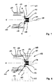
- FIG. 1 there is illustrated a motor, shown generally by reference numeral 100 and with respect to a substrate such as the back of a vacuum fluorescent display (VFD) unit 102. It is to be understood that the VFD unit 102 is not illustrated to scale.
- VFD vacuum fluorescent display
- the motor 100 can be generally described as a surface-mountable, brushless dc motor having a stator assembly shown generally by reference numeral 110.
- the stator assembly 110 includes an integrally formed stator 112 made of a ferromagnetic material and has a central portion with an aperture (not specifically illustrated) extending completely therethrough and three T-shaped equally-spaced, lobes or poles 114.
- the stator 112 is constructed of SAE 1005 carbon steel.
- the stator 112 has a diameter of 0.33" and is 0.32" long.
- each lobe 114 of the stator 112 includes a downwardly projecting mounting tab 116 which is received and retained on a corresponding pad 148 formed on the back of the VFD unit 102.
- the coils 118 can be electrically interconnected as a Delta connection, a Star connection or a Grounded-Star connection, respectively.
- Each type of connection offers a different level of motor control and efficiency. For example, a control voltage on any of the nodes A, B or C in a Delta connection affects all three coils, whereas a voltage on any of the nodes A, B or C in a Grounded-Star affects only one coil.
- the Grounded-Star offers the greatest level of flexibility in control strategy, and is more efficient than a Delta connection.
- connection of Figure 2c may be held at a predetermined reference level.
- the Delta connection of Figure 2a results in a higher torque for any given voltage.
- the torque can be as much as 50% higher for a similar voltage applied to the Star or Grounded-Star connection.
- the Delta connection is easier to manufacture since there are fewer terminations and the coils 118 can be wound in a continuous fashion. In the preferred embodiment, therefore, a Delta connection is utilized.
- each coil 118 is wound with approximately 150 turns of #38 AWG magnet wire, yielding a coil node resistance of approximately 5n when Delta connected. It should be appreciated that this construction results in a very low-cost and compact stator assembly 110. Additionally, since each of the coils 118 has a ferromagnetic core, the magnetic fields created when the coils 118 are energized are amplified. Consequently, the stator assembly 110 and therefore, the motor 100, has a low power consumption and high torque.
- a rotor assembly shown generally by reference numeral 130, includes a plastic cap 132, a magnet 134, an annular plastic ring 136 and a motor output shaft 138, all of which are secured together for rotation with respect to the stator assembly 110.
- the magnet 134 is a ceramic magnet having a height of 0.40", an inner diameter of 0.37" and an outer diameter of 0.62".
- the magnet 134 is magnetized through its diameter to produce North and South poles.
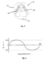
- a nearly sinusoidal magnet flux profile shown in Figure 3 was utilized. As illustrated in Figure 3, the magnet flux profile preferably has a peak flux of about 400 gauss (with an empty core).
- V 1 SIN ( X )
- V 2 SIN ( X + 120°)
- V 3 SIN ( X + 240°) where "X°" represents the desired angular position from 0° to 360°.
- Coil voltages that are phase shifted by 120° work well the geometry of the coils 118.
- the drive voltages are shown to be generally sinusoidal, any other waveform, such as a square or triangle waveform, could be utilized.
- peak drive current is approximately 0.25A per coil 118.
- FIG. 5 there is shown an alternative stator 112 and coil 118 assembly, wherein the number of stator lobes 114, or poles, exceeds the number of coils 118 wound thereabout.
- two coils 118 are wound about the three-lobed stator 112 and electrically connected at node "B".
- the two coils could be wound about any two of the lobes.
- a third coil is absent, a third stator lobe is required for magnetic balancing.
- the drive voltages for the stator/coil arrangement shown in Figure 5 are preferably sinusoidal in shape and phase shifted from each other by about 120°, as previously described with respect to the motor embodiment shown in Figure 1. Utilizing these drive voltages, the available angular sweep of the 2-coil embodiment remains a full 360°, although a reduced angular sweep is also possible. The torque delivered, however, is generally non-uniform. The reduction in the number of parts due to the absent coil and the reduced manufacturing time results in a cost savings.
- the 2-coil embodiment is thus ideal for use in an application which requires a reduced angular sweep, such as a fuel gauge in an automotive instrument cluster.
- the motor 100 may be constructed to provide such a reduced set of positions.
- the coils 118 are preferably wound about the stator lobes 114 with about 200 turns of #39 AWG wire, so as to yield node resistances of about 10n.
- the ceramic magnet 134 is preferably magnetized with an approximately trapezoidal flux profile, shown in Figure 6. As illustrated in Figure 6, the trapezoidal flux profile has a peak flux of approximately 1350 gauss.
- the magnet 134 is affixed to the plastic cap 132 on one face thereof and the plastic ring 136 is affixed to the other face of the magnet 134.
- the output shaft 138 is formed on or otherwise attached to the plastic cap 132 at the end thereof.
- the output shaft 138 is sized to extend through the magnet 134 and the plastic ring 136.
- the magnet 134 is shown to be a generally cylindrical magnet, the magnet could be constructed as a band or ring with a plurality of individual magnets disposed thereabout.
- a thrust washer 140 is preferably positioned on the output shaft 138 between the plastic cap 132 and the stator assembly 110.
- a pair of optional press-in bushings 122 and 124 are also preferably positioned at the top and bottom of the stator 112, respectively, within its central aperture to help align the output shaft 138.
- the output shaft 138 extends through the thrust washer 140, the bushing 122, the aperture of the stator 112 and the bushing 124, such that the magnet 134 surrounds, or is without, the stator 112 and the coils 118 supported thereon and immediately adjacent thereto. This construction provides a compact closed magnetic circuit with a small air gap.
- the magnet 134 Due to the ferromagnetic nature of the stator 112, the magnet 134 generally centers itself on the magnetic center of the stator, which is at or slightly before the center of mass of the stator. This construction results in the motor 100 having an inherent, self-correcting position memory. This self-correcting feature allows the motor 100 to correct for any positioning problems every time the coils 118 are energized. Thus, positioning inaccuracies are remedied with the next position adjustment. Additionally, the motor 100 has a stable "off" (i.e. unpowered) position. These features give the motor 100 an advantage over stepper-type motors, which have inherent positioning problems.
- a cap 142 encloses the assembled motor 100.
- the cap 142 includes a plurality of mounting tabs 144, thereby permitting the motor 100 to be surface-mounted on the VFD unit 102 or some other substrate, such as a circuit board (not specifically illustrated), with the output shaft 138 extending therethrough as described below.
- the cap 142 is intended to function as both a magnetic flux concentrator for the magnet 134 and as a magnetic shield for the entire motor assembly, preventing external magnetic fields from adversely affecting motor performance and is constructed of an appropriate steel.
- the cap 142 serves the additional function of protecting the motor assembly from the environment, such as dust, dirt and the like.
- an inverted cup-shaped cap 150 shown in phantom in Figure 1, could be utilized in place of the cap 142 and plastic cap 132.
- the cap 150 is constructed of low carbon steel with the motor shaft 138 being formed thereon.
- the cap 150 is a unitary piece and is sized (e.g. 0.030" thick and approximately 0.500" long) to substantially enclose the magnet 134 and stator assembly 110 and the rotor assembly 130.
- the cap 150 provides protection for the motor assembly from the environment.
- the cap 150 serves the dual functions of a magnetic flux guide and concentrator for the magnet 134, which is preferably press-fitted into the cap 150, and as an electromagnetic shield for the motor assembly, preventing external magnetic fields from affecting the performance of the motor 100.
- the output shaft 138 also preferably extends through a piezoelectric brake 146 and the VFD unit 102.
- a glass tube 152 extends through the VFD unit 102, permitting the shaft 138 to extend therethrough while maintaining the vacuum within the VFD unit.
- the glass tube 152 also acts as a bearing to facilitate shaft rotation.
- two conductive electrical traces 154 located on the VFD unit 102 provide power and ground to the piezoelectric brake 146 and, in one embodiment, ground to the coils 118, thereby allowing the motor 100 and brake 146 to be accurately controlled, as described in greater detail hereinbelow.
- One of the traces 154 defines a power ring 156 and the other trace defines a ground ring 158 for the piezoelectric brake 146.
- the brake 146 is typically soldered to the rings 156 and 158.
- Three other traces 160 supply power to the coils 118.
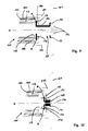
- the motor 100 is mounted on a substrate 164, such as a circuit board.
- the substrate 164 includes a tube 166 which extends therethrough and receives the motor shaft 138.
- the tube 166 is constructed of stainless steel, and has an inner diameter approximately 0.001" larger than the diameter of the shaft 138 to provide a bearing surface.
- the inside surface of the tube 166 could be grooved to reduce the surface area contacting the shaft 138, thereby reducing the friction.
- a motor commutator 168 is fixedly attached to the substrate 164 by solder 171 or the like and includes three segments, two of which are illustrated.
- the commutator 168 also includes a plurality of coil terminators 172, each in electrical communication with an associated commutator segment.
- the coil terminators 172 are in electrical communication with the coil nodes A, B and C, only two of which are illustrated in Figure 7.
- a brake disc 170 is supported by the commutator.
- the brake disc 170 is constructed of a low carbon steel, is 0.030" thick and has a 0.35" outer diameter.
- the brake disc 170 and the stator i.e. the stator lamination stack
- the brake disc 170 causes the magnet 134 to be displaced from its magnetic balance position by 0.020" with respect to the stator 112.
- the stator 112 and magnet 134 are caused to re-align, freeing the magnet 134 from the brake surface for rotation.
- the motor 100 is mounted on a substrate 164, such as a circuit board.
- the substrate 164 could be a flex-strip, including electrical conductors, which is electrically connected to a circuit board 174, assuming proper support (not specifically illustrated) is provided for the motor 100.
- a stator shaft 176 provides support for rotation of the magnet 134 and the cap 150 about the stator 112.
- the motor commutator 168 is preferably fixedly attached to the substrate 164 by solder 171 or the like and includes three segments, two of which are illustrated.
- the commutator 168 also includes a plurality of coil terminators 172, each in electrical communication with an associated commutator segment.
- a rotor support 178 includes a ring portion 180 which is preferably affixed to the cap 150 to provide proper alignment.
- the ring portion 180 includes a central aperture through which the commutator 168 extends.
- the rotor support 178 also preferably includes an arm portion 182, which is formed on the ring portion 180.
- the rotor support 178 i.e. the ring portion 180 and the arm portion 182 rotates about the motor axis "H".
- FIG. 9 there is shown another alternative bearing embodiment for the motor 100.
- the motor 100 is preferably mounted on a substrate 164, such as a circuit board.
- a connector bearing assembly shown generally by reference numeral 184 replaces the commutator 168 of the previous two bearing embodiments shown in Figures 7 and 8.
- the connector bearing 184 includes a plurality of coil terminators 186 which extend through the connector bearing 184 from a point inside the motor 100 to the substrate 164.
- the coil terminators 186 are electrically connected to coil termination wires 188 which are thus in electrical communication with the substrate 164.
- the coil terminators 186 cooperate with the substrate 164 so as to form either a surface mounting connection shown generally by reference numeral 190 or a through-hole connection shown in phantom generally by reference numeral 192.
- a bearing cap 194 is affixed to the magnet 134 and the cap 150.
- the bearing cap 194 is constructed of Delrin and includes a central aperture through which the connector bearing 184 extends. The bearing cap aperture is sized such that the connector bearing 184 contacts the bearing cap, creating a bearing surface 196.
- the commutator 168 provides the bearing surface and the means through which the coils are electrically connected to the substrate 164, such as a circuit board.
- the commutator 168 is fixedly attached to the substrate 164 by solder 171 or the like and includes three segments, two of which are illustrated.
- the commutator 168 also includes three coil terminators 172, each in electrical communication with an associated commutator segment.
- the coil terminators 172 are in electrical communication with the coil nodes A, B and C, only two of which are illustrated in Figure 10.
- the stator shaft 176 extends through the commutator 168 and the substrate 164.
- a generally circular shaped bearing cap 202 is affixed to the magnet 134 and the cap 150 for rotation therewith.
- the bearing cap 202 is preferably constructed of Delrin and includes a central aperture disposed therein through which the commutator 168 extends.
- the piezoelectric brake 146 is generally concave in shape in its "unpowered” state.
- the piezoelectric brake 146 is normally biased against the plastic ring 136, i.e. the brake is normally "set”, thereby preventing rotation of the output shaft 138 and any load attached thereto, (e.g. a pointer) after the load is in a desired position.
- the brake 146 When the brake 146 is energized, however, it deflects generally flat and away from the plastic ring 136, releasing the brake 146 and freeing the output shaft 138 to rotate to a new desired angular position.
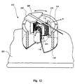
- braking of the motor 100 can be achieved without the use of the piezoelectric brake 146. Since the stator 112, as shown in Figure 1, has more magnetic mass on "top” than on “bottom”, it therefore has a magnetic center located above its physical center. As described in greater detail above, the magnet 134 centers itself around the magnetic center.
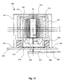
- the stator assembly 210 includes an integrally formed ferromagnetic stator 212 having a central portion with an aperture (not specifically illustrated) extending completely therethrough and three generally T-shaped equally-spaced, lobes or poles 214.
- Each lobe 214 of the stator 212 has an integrally-formed, downwardly projecting magnetic leg 216 which passes through or around a generally annular magnetically permeable base 218.
- the magnetically permeable base 218 has an axially projecting lip portion 220 which cooperates with the rest of the magnetic circuit to provide an essentially closed-loop flux path.
- the magnetically permeable base 218 is preferably positioned centrically within and fixedly attached to a substrate, such as a circuit board 222.
- the legs 216 of the stator assembly 210 permit surface mounting to the circuit board 222. This design results in the combined magnetic permeability center of the assembly 210 and the base 218 to be located at a position, labeled as "D", being below its electromagnetic center, labelled as "E” in Figure 11.
- the magnetic permeability center "D" of the stator 212 and magnetically permeable base 218 causes the center of magnetism in the magnet 134 to seek the level "D".
- the magnet 134 contacts brake element 224 and stops at level "F".
- the surface of brake element 224 can be textured or the material can be selected to achieve coefficient(s) of friction as desired. If the magnetic base 218 were not present, the magnet's center of magnetism would be attracted only to the stator 131 and the magnet would tend to seek level "E".
- the magnet 134 With the magnetic base 218 in place as shown in Figure 11, the magnet 134 will move “down” from level “E” toward level “D” and will stop at level “F” due to the magnet 134 contacting the brake element 224.
- the magnet 134 is held in place and prevented from rotating about motor axis "G”, thereby holding pointer 226 in place, which is affixed to magnet 134 by the shaft 138.
- the control means applies a drive voltage to one or more of the coils 118, causing an electromagnetic field to be set up at level "E".
- This magnetic field at level “E” is generally attracting the center of magnetism of magnet 134 toward that level.
- the center of magnetism of magnet 134 is attracted to level “D” due to the permeability of magnetic base 218.
- the drive voltage(s) applied to the coil(s) 118 should be capable of rotating the pointer 226 to the new angular position about axis "G" and also be capable of releasing the magnet 134 from the brake 224.
- power is removed from coils 118, allowing the magnet 134 to be pulled down to level "F” and be held by brake 224 until it is desired to move the pointer 226 to a new position.
- the motor 230 is a front mount design, capable of being surface-mounted to the front of the substrate, such as a circuit board 222 or the VFD 102 shown in Figure 1.
- the pointer 226 is fixedly attached to a lid 232, instead of being affixed to the motor output shaft.
- the lid 232 is constructed of plastic and is fixedly attached to the magnet 134 for rotation therewith relative to the stator assembly, shown generally by reference numeral 234.
- the stator assembly 234 includes a stator 236, which is substantially similar to the stator 212 previously described. The stator 236, however, is without an aperture extending through its central portion.
- the coil drive system 240 preferably includes a microprocessor 242, a digital-to-analog (D/A) converter 244, gain and offset circuitry 246 and a power amplifier stage shown generally by reference numeral 248.
- the microprocessor 242 such as a 68HC05 series microprocessor, commercially available from Motorola, of Phoenix, Arizona, United States of America, reads and processes inputs from sensors not specifically illustrated to generate a desired angular position for the motor.
- data corresponding to the coil drive voltages (shown in Figure 4) are stored in look-up table in memory not specifically illustrated.
- This desired position is communicated as a digital signal to the D/A 244, such as 86021, an 8-bit, 4-channel D/A commercially available from the Microelectronics IC Divisions of Fujitsu, of San Jose, California, United States of America, which converts the digital signal to a corresponding analog signal.
- the microprocessor 242 and the D/A 244 are assured by standard control and decoding logic 250, which functions to select a D/A channel, and the like.
- the analog position signal is next communicated to the appropriate gain and offset circuitry 246 and the power amplifier stage 248.
- the power amplifiers 248 function to amplify the sinusoidal coil drive voltage signals, which can be at rather low levels, preferably to values of between approximately 3V to approximately 7V.
- Position sensor circuitry 252 monitors the coil voltages and provides position feedback signals related to the angular position of the motor shaft to the microprocessor 242.
- the microprocessor based system 240 is fully programmable, providing for control of actual gauge movement through coil energization as well as providing for control of "when" the coils are energized.
- the coil drive system 260 includes an analog-to-digital (A/D) converter 262, an electrically programmable read-only memory (EPROM) 264, a D/A 266, gain and offset circuitry shown generally by 268 and a power amplifier stage shown generally by 270.
- An analog voltage signal (V in ) such as from a fuel level sensor, is provided to the A/D 262, such as ADC0808, commercially available from National Semiconductor, of Santa Clara, California, United States of America.
- the A/D 262 converts this analog signal, approximately every four (4) clock ticks, to a corresponding digital signal and communicates the digital signal to the EPROM 264.
- the digital signal actually represents a base address in the EPROM, which address contains digital data representing coil drive voltage for a node (e.g. node A).
- the coil drive voltages for nodes B and C are preferably located in the next two address locations, which are accessed after appropriate signal from the 2-bit counter are communicated to the EPROM.
- the EPROM 264 provides the data required to generate the sinusoidal drive voltages (such as those shown in Figure 4) to rotate the motor to the desired angular position.
- the EPROM 264 could have data representing any other waveform, such as a square or triangle waveform.
- the digital data is communicated by the EPROM 264 to the D/A 266.
- the 2-bit counter 272 provides channel select data to the D/A 266. Further processing of the coil drive voltages by the gain and offset circuitry 268 and the power amplifiers 270 is substantially the same as described above with reference to Figure 13.
- the programmable drive system 260 is a continuous system, in that V in is read and the motor is driven.
- FIG. 15 there is illustrated a block diagram for an alternative piece-wise linear 3-coil motor drive system, shown generally by reference numeral 280.
- the embodiment is shown for use with a motor utilized in a engine speed gauge of a vehicular instrument cluster.
- an input signal such as from an engine speed sensor (not specifically illustrated)
- the signal processing circuitry shown generally by reference numeral 282 which processes by introducing a gain which varies according to the number of cylinders in the engine of the vehicle.
- This signal is generally indicative of the desired angular position of the pointer associated with the gauge (e.g. the gauge pointer should be located at 65 mph).
- This signal is then communicated to a waveform generator 284, such as an LM1819, commercially available from National Semiconductor, of Santa Clara, California, United States of America.
- the waveform generator functions as a converter from frequency to voltage, preferably generating sine and cosine waveforms.
- These sine and cosine waveforms are then processed by standard offset and gain circuitry, shown generally by reference numeral 286.
- a "copy" of the sine waveform is communicated directly to the power amplifiers 292.
- a “copy” of the both the sine and cosine waveforms is processed by phase shifting circuitry shown generally by reference numeral 288 and combined prior to being communicated to an amplifier 292.
- the phase shifting circuitry 288 multiplies the sine waveform by a first constant (i.e. -0.5) and multiplies the cosine waveform by a second constant (i.e. -0.866).
- the circuitry 288 functions to generate a phase shifted sine waveform (e.g. X + 120°).
- the other "copy" of the waveform is processed by the phase shifting circuitry shown generally by reference numeral 290, which functions similarly to generate a second phase shifted sine waveform (e.g. X + 240°).
- FIG. 16 illustrates sample coil drive voltage waveforms, plotted versus angular position, generated by the coil drive system shown in Figure 15. As shown on the horizontal axis, only approximately 190° of the waveforms generated by the waveform generator 284 are graphed. However, the circuit has the capability to produce a full 360° of rotation. Since the waveform generator 284 only generates approximations of sine and cosine waves, some inaccuracies, such as the plateau on the voltage waveform for node "A", are to be expected. Such inaccuracies do not, however, significantly affect positioning accuracy.
- the 2-coil drive system 300 includes a frequency-to-voltage converter 302, offset and gain circuitry shown generally by 304 and a transistor power stage shown generally by 306 including a plurality operational amplifiers and transistors.
- an input signal such as from an engine speed sensor (not specifically illustrated) is provided to the frequency-to-voltage converter circuitry 302, such as an LM2917, commercially available from National Semiconductor, of Santa Clara, California, United States of America, which outputs an analog voltage signal.
- the analog voltage signal is then processed by standard offset and gain circuitry 304, which outputs a generally linear ramp to the clipper circuits 308 and 310 of the transistor power stage.
- Clipper circuit 308 is also provided with a reference voltage (VA ref ), which represents the voltage level the clipper circuit 308 clips the linear ramp.
- VA ref reference voltage
- the output of the clipper circuit 308 is communicated to negative gain circuitry 312, which functions to invert the clipped linear ramp.
- the output of the gain circuitry 312 is then communicated to the associated operational amplifier/transistor for application to the coil node "A".
- the drive voltage for node "C” is generated with substantially similar circuitry, except that positive gain circuitry 314 utilized (i.e. the clipped ramp is not inverted).
- Typical coil drive voltages for nodes "A” and “C” are illustrated in Figure 18. Since there are only two coils, node “B” is maintained at a positive bias voltage level, as illustrated in Figure 18.
- node “B” operates to both source and sink current.
- node “B” acts as a current sink for the current flowing from “A” and a current source for current flowing to node “C”.
- node “B” acts as a current sink for the current flowing from node "C” and a current source for current flowing to node "A”.
- FIG. 19 there is illustrated a schematic diagram for a basic passive coil drive system, shown generally by reference numeral 320.
- an analog voltage signal is generated, such as by a fuel level sensor.
- this analog voltage signal is then communicated to coil node "B" to set up a reference voltage level at node "B".
- coil node "A” is electrically connected to a voltage source (V + ) and coil node “C” is electrically connected to a ground potential.
- current (i) flows in the direction indicated by the arrows.
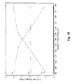
- Figure 20 is a graphical representation of the relationship between sensor voltage (i.e. voltage at node "B") and corresponding gauge position (°). As shown, there is generally a linear relationship between sensor voltage and gauge position.
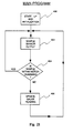
- a flow chart illustrates the program flow for use with the microprocessor-based drive system 240 shown in Figure 13.
- the microprocessor ( ⁇ P) 242 enters a start-up and initialization phase, which includes resetting variables, checking memory, and the like.
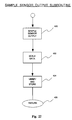
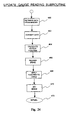
- the ⁇ P 242 reads sensor output, and program flow is transferred to the "Sample Sensor Output" subroutine shown in Figure 22.
- the ⁇ P 242 acquires output from sensors, such as an engine speed sensor. If the sensor output is analog, an internal A/D converts the output into digital format for further processing. Due to the differences in the type of sensors that could be providing data to the ⁇ P 242, sensor output can vary drastically in magnitude. For the most accurate processing, therefore, the digitized sensor output is scaled at step 432.
- the scaled data is then verified and stored in an internal volatile memory element or random-access memory (RAM) of the ⁇ P 242 at step 434.
- RAM random-access memory
- Data verification insures detection of sensor deterioration and/or failure.
- program flow is returned to the main program shown in Figure 21.
- the ⁇ P 242 determines if the scaled sensor output is within a deadband of the motor 100.
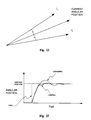
- the deadband represents the required minimum change in angular position of the motor 100 and is illustrated graphically in Figure 23.
- the new angular position of the motor 100 is outside of the upper limit l u or the lower limit l l (i.e. move through an angle of ⁇ °) before the ⁇ P 242 will energize the coils 118 and update its gauge position.
- the ⁇ P 242 first determines the numerical difference between the scaled sensor output and the scaled data value representing the current angular position of the motor 100. If this difference would translate to a change in angular position exceeding the deadband, the pointer position is updated.
- program flow is transferred to the "Update Gauge Reading” subroutine shown in Figure 24.
- the scaled data is retrieved from the RAM memory at step 460.
- the data is then converted to a value representative of a corresponding desired motor angular position.
- the sensor reading may correspond to a new speed of which is converted to an angular position of X°, as indicated on the graph.
- the ⁇ P 242 then performs a data table look-up of data stored in a read-only memory (ROM), not specifically illustrated, utilizing the desired motor angular position data.
- the ROM preferably contains a table containing data representing drive voltages for the coils 118. Generally, every angular position of motor 100 can be characterized by a unique set of coil voltages, as previously shown in Figure 4.
- the ⁇ P 242 utilizes the set of data voltages to calculate the output function to be applied to each of the coils 118.
- the ⁇ P 242 energizes the piezoelectric brake 146 (shown in Figure 1) at step 466. As previously described, this deflects the brake flat, thereby releasing the rotor assembly 130, allowing the motor output shaft 138 to rotate.
- the ⁇ P 242 energizes the coils 118 according to the output function.
- the output shaft 138 then rotates to the desired angular position.
- the ⁇ P 242 removes power from the piezoelectric brake 146.
- the brake 146 thus returns to its concave shape and is set against the rotor assembly 130, thereby preventing further rotation.
- the use of the piezoelectric brake 146 may allow for the precise control of the response of the motor 100 to an output function.
- Figure 25 illustrates the relationship between an ideal motor response (i.e. a step response), a damped motor response and an undamped motor response over time. Specifically, various levels of brake application during shaft rotation may minimize overshoot and fix the angular position quickly and accurately.
- a position feedback signal related to the position of the load can be generated by energizing one of the coils 118, such as in the delta connection of Figure 2A, and sensing any resulting current or voltage appearing across one or both of the other coils.
Landscapes
- Engineering & Computer Science (AREA)
- Power Engineering (AREA)
- Physics & Mathematics (AREA)
- Electromagnetism (AREA)
- Connection Of Motors, Electrical Generators, Mechanical Devices, And The Like (AREA)
- Brushless Motors (AREA)
- Control Of Motors That Do Not Use Commutators (AREA)
Claims (20)
- Moteur électrique (100) pour faire tourner une charge à une position angulaire souhaitée en réponse à un signal de détecteur, le moteur électrique (100) comprenant un ensemble de stator (110) comprenant un stator (112) ayant une pluralité de lobes (114), le stator comprenant au moins une bobine (118) enroulée autour d'au moins un lobe de la pluralité de lobes (114), chaque bobine (118) ayant une paire de fils conducteurs d'entrée ;un ensemble de rotor (130) comprenant un aimant (134) ayant une pluralités de pôles, et des moyens de connexion (168) pour connecter électriquement les fils conducteurs de ladite au moins une bobine pour former une borne d'entrée, le moteur (100) étant caractérisé par :le fait que l'aimant (134) est magnétisé selon un profil de flux magnétique ayant une amplitude qui varie de manière sensiblement sinusoïdale avec la position angulaire, l'aimant (134) étant adapté pour être couplé à la charge et positionné en rotation par rapport à l'ensemble de stator (110) ; etle fait que l'ensemble de rotor (130) tourne par rapport à l'ensemble de stator (110) en réponse à un signal électrique variable sensiblement en continu appliqué à la borne d'entrée pour positionner angulairement l'ensemble de rotor (130) à l'une quelconque d'une pluralité de positions indépendantes de la géométrie du stator (112), la position angulaire de la charge variant de manière généralement linéaire avec le signal du détecteur.
- Moteur électrique (100) selon la revendication 1, caractérisé en ce que l'ensemble de rotor (130) comprend un arbre (138) adapté pour être couplé à la charge, l'arbre s'étendant à travers ledit stator (112).
- Moteur électrique (100) selon la revendication 1, caractérisé en ce que le stator (112) a un nombre impair de lobes (114), le stator (112) comprenant au moins une bobine (118) enroulée autour d'au moins un des lobes (114) et dans lequel l'aimant (134) a un nombre pair de pôles.
- Moteur électrique (100) selon la revendication 1, caractérisé par :
des moyens de commande (242) destinés à commander le mouvement de la charge et à appliquer un signal électrique variable sensiblement en continu à la borne d'entrée pour faire tourner l'ensemble de rotor (130) par rapport à l'ensemble de stator (110) à l'une quelconque d'une pluralité de positions angulaires, indépendante de la géométrie du stator. - Moteur électrique (100) selon la revendication 1, caractérisé en ce que le stator (112) comprend une pluralité de lobes (114), ayant chacun une bobine (118) enroulée autour de lui.
- Moteur électrique (100) selon la revendication 1, caractérisé en ce que la charge est un pointeau à aiguille.
- Moteur électrique (100) selon la revendication 1, caractérisé par une couche en matériau isolant et sur laquelle l'ensemble de stator est attaché de manière fixe.
- Moteur électrique (100) selon la revendication 2, caractérisé par :
des moyens de palier destinés à supporter en rotation l'arbre (176) dans l'ensemble de stator (110) tout en permettant à l'arbre (176) de tourner librement par rapport à l'ensemble de stator (110). - Moteur électrique (100) selon la revendication 1, caractérisé par : une couche de matériau isolant (164) sur laquelle sont formés des conducteurs électriques, les lobes de stator (114) étant faits d'un matériau magnétiquement perméable et étant positionnés angulairement l'un par rapport à l'autre, ladite au moins une bobine (118) étant électriquement connectée aux conducteurs respectifs.
- Moteur électrique (100) selon la revendication 9, caractérisé en ce que la couche de matériau isolant (164) a une surface arrière, le stator (112) étant attaché de manière fixe à la surface arrière de la couche et dans lequel lesdites bobines (118) réagissent au flux d'énergie électrique pour provoquer le déplacement dudit ensemble de rotor contre la surface arrière de ladite couche, fournissant ainsi une force de freinage audit ensemble de rotor (130).
- Moteur électrique (100) selon la revendication 1, caractérisé en ce que l'ensemble de stator comprend trois bobines, les bobines étant positionnées à 120° l'une de l'autre.
- Moteur électrique (100) selon la revendication 11, caractérisé en ce que les bobines (118) sont connectées selon une connexion en triangle.
- Moteur électrique (100) selon la revendication 11, caractérisé en ce que les bobines (118) sont connectées selon une connexion en étoile.
- Moteur électrique (100) selon la revendication 11, caractérisé en ce que les bobines (118) sont connectées selon une connexion en étoile mise à la terre.
- Moteur électrique (100) selon la revendication 4, caractérisé en ce que les moyens de commande (242) sont constitués d'une commande en boucle fermée comprenant des moyens pour générer un signal de rétroaction de position lié à la position de la charge.
- Moteur électrique (100) selon la revendication 15, caractérisé par des moyens (252) pour générer un signal de rétroaction de position lié à la position de la charge.
- Moteur électrique (100) selon la revendication 1, caractérisé par : une couche de matériau isolant (164) sur laquelle sont formés des conducteurs électriques, le stator (112) étant lié de manière fixe à la couche et dans lequel le moteur électrique (100) comprend en outre un transducteur piézo-électrique (146) électriquement connecté aux conducteurs et disposé entre l'ensemble de rotor (130) et la couche de matériau isolant (164), ledit transducteur piézo-électrique (146) réagissant au flux d'énergie électrique pour fournir une pression audit ensemble de rotor (130), fournissant ainsi une force de freinage audit ensemble de rotor (130).
- Procédé pour commander un moteur électrique destiné à entraíner une charge, le moteur électrique (100) ayant un ensemble de stator (110) et un ensemble de rotor (130) en rotation par rapport à l'ensemble de stator, le procédé étant caractérisé par les étapes consistant à :prévoir une surface de freinage (224) ;pourvoir l'ensemble de stator d'un centre de perméabilité magnétique "D", décalé de son centre électromagnétique "E" ;alimenter l'un des deux ensembles avec au moins un signal électrique variable sensiblement en continu de manière à produire une force axiale entre les deux ensembles pour éloigner l'ensemble de rotor (130) de la surface de freinage (224) et à produire une force de rotation destinée à faire tourner l'ensemble de rotor à une position souhaitée ; etcesser d'alimenter cet ensemble de manière à permettre à l'ensemble de rotor de venir contre la surface de freinage (224) pour maintenir l'ensemble de rotor à l'emplacement souhaité.
- Procédé selon la revendication 18, caractérisé par les étapes consistant à :générer un signal de position angulaire représentant la position souhaitée ;générer un signal de référence représentant une deuxième position ;prévoir une plage de positions comprenant la position souhaitée, la plage de positions étant représentative de la plage d'insensibilité du moteur ;traiter les signaux pour obtenir un signal traité et empêcher la rotation de l'ensemble de rotor de la position souhaitée à la deuxième position lorsque la deuxième position est dans la plage sur la base du signal traité.
- Procédé pour monter un moteur miniature (100), destiné à faire tourner avec précision une charge à une position angulaire souhaitée en réponse à un signal de détecteur, sur un substrat sur lequel sont formés des conducteurs électriques, le procédé comprenant les étapes consistant à :former un noyau statorique à partir d'une pluralité de tôleries, le noyau statorique ayant une pluralité de lobes (214) ; enrouler au moins une bobine autour d'un lobe du stator associé, ladite au moins une bobine ayant une paire de fils conducteurs ; et caractérisé par les étapes consistant à :prévoir des moyens de connecteur de bobine positionnés entre le moteur et le substrat, les moyens de connecteur de bobine comprenant une pluralité de terminaisons (188) ;connecter électriquement les fils conducteurs de ladite au moins une bobine à une terminaison associée des moyens de connecteur de bobine ;lier de manière fixe les moyens de connecteur de bobine (118) au substrat de manière à ce que les moyens de connecteur de bobine soient électriquement couplés aux conducteurs électriques ;magnétiser un aimant permanent (134) avec un flux magnétique ayant une amplitude qui varie de manière sensiblement sinusoïdale avec la position angulaire, l'aimant entourant le noyau statorique ; etprévoir un rotor (130) comprenant l'aimant permanent entourant le noyau statorique pour être en rotation par rapport à celui-ci, en réponse à un signal électrique variable sensiblement en continu appliqué aux conducteurs électriques.
Applications Claiming Priority (3)
| Application Number | Priority Date | Filing Date | Title |
|---|---|---|---|
| US696014 | 1985-01-29 | ||
| US69601491A | 1991-05-09 | 1991-05-09 | |
| PCT/US1992/003907 WO1992020080A1 (fr) | 1991-05-09 | 1992-05-11 | Moteur electrique, dispositif de commande et procedes de commande et de montage |
Publications (3)
| Publication Number | Publication Date |
|---|---|
| EP0694203A4 EP0694203A4 (fr) | 1994-08-30 |
| EP0694203A1 EP0694203A1 (fr) | 1996-01-31 |
| EP0694203B1 true EP0694203B1 (fr) | 1998-04-15 |
Family
ID=24795358
Family Applications (1)
| Application Number | Title | Priority Date | Filing Date |
|---|---|---|---|
| EP92911720A Expired - Lifetime EP0694203B1 (fr) | 1991-05-09 | 1992-05-11 | Moteur electrique, procedes de commande et de montage |
Country Status (6)
| Country | Link |
|---|---|
| US (1) | US5355373A (fr) |
| EP (1) | EP0694203B1 (fr) |
| JP (1) | JP3249518B2 (fr) |
| AU (1) | AU1896192A (fr) |
| DE (1) | DE69225149T2 (fr) |
| WO (1) | WO1992020080A1 (fr) |
Cited By (4)
| Publication number | Priority date | Publication date | Assignee | Title |
|---|---|---|---|---|
| WO2005048436A2 (fr) | 2003-11-13 | 2005-05-26 | Sew-Eurodrive Gmbh & Co. Kg | Entrainement compact, reducteur conique a decalage axial et procede pour produire un entrainement |
| WO2007076976A1 (fr) | 2006-01-03 | 2007-07-12 | Sew-Eurodrive Gmbh & Co. Kg | Dispositif |
| EP2264863A2 (fr) | 2003-11-13 | 2010-12-22 | SEW-EURODRIVE GmbH & Co. KG | Entrainement compact |
| DE102006060865B4 (de) * | 2006-01-03 | 2015-08-13 | Sew-Eurodrive Gmbh & Co Kg | Vorrichtung |
Families Citing this family (16)
| Publication number | Priority date | Publication date | Assignee | Title |
|---|---|---|---|---|
| DE69428670T2 (de) * | 1994-01-28 | 2002-07-11 | International Business Machines Corp., Armonk | Aufprallvermeidungsschockring zum Schutz von Plattenantriebsmotorlagerungen |
| DE19753776A1 (de) * | 1997-12-04 | 1999-06-10 | Bosch Gmbh Robert | Meßvorrichtung zur berührungslosen Erfassung eines Drehwinkels |
| US5990584A (en) * | 1998-08-25 | 1999-11-23 | Eaton Corporation | Direct current torque motor with extended stator poles |
| US6365995B1 (en) * | 1998-11-20 | 2002-04-02 | Matsushita Electric Industrial Co., Ltd. | Brushless motor and its assembly method |
| ES2195838T3 (es) * | 1999-06-17 | 2003-12-16 | Goodrich Control Sys Ltd | Conjunto de frenos. |
| US6097120A (en) * | 1999-09-04 | 2000-08-01 | Sunonwealth Electric Machine Industry Co., Ltd. | Brushless D.C. motor assembly |
| US6906440B1 (en) | 2000-06-13 | 2005-06-14 | General Electric Canada, Inc. | Bracket assembly having a plurality of plates for a dynamoelectric machine |
| US6727626B2 (en) * | 2002-04-17 | 2004-04-27 | Sunonwealth Electric Machine Industry Co., Ltd. | Balancing plate for a motor |
| JP4084982B2 (ja) * | 2002-09-12 | 2008-04-30 | 株式会社ケーヒン | ブラシレスモータの駆動装置及び駆動方法 |
| US7610942B2 (en) * | 2003-01-15 | 2009-11-03 | Amnis Corporation | Cell suspension rotating fluidic pump |
| JP4406864B2 (ja) * | 2003-09-30 | 2010-02-03 | 株式会社ヴァレオサーマルシステムズ | 電磁モータ |
| US7663279B2 (en) * | 2006-12-20 | 2010-02-16 | Metal Industries Research & Development Centre | Motor module |
| WO2010128365A1 (fr) * | 2009-05-07 | 2010-11-11 | Aktiebolaget Skf | Procédé et dispositif permettant de commander un moteur sans balais |
| US9844828B2 (en) * | 2012-08-31 | 2017-12-19 | Illinois Tool Works Inc. | Wire feeder assembly with motor mount |
| RU2546406C1 (ru) * | 2013-11-29 | 2015-04-10 | Общество с ограниченной ответственностью "Эйдос-Медицина" | Привод для генерации обратной тактильной связи на инструмент по усилию |
| WO2018137179A1 (fr) | 2017-01-25 | 2018-08-02 | Microsoft Technology Licensing, Llc. | Moteur pas-à-pas à utiliser dans un ensemble de commande de rotation de dispositif d'entrée |
Family Cites Families (12)
| Publication number | Priority date | Publication date | Assignee | Title |
|---|---|---|---|---|
| US3110830A (en) * | 1962-04-16 | 1963-11-12 | Electro Counter & Motor Corp | Rotor brake |
| US3350709A (en) * | 1964-07-07 | 1967-10-31 | Bendix Corp | Electromagnetic indicator device with magnetic locking means |
| US3970980A (en) * | 1975-05-15 | 1976-07-20 | Victor Nelson | Rotary actuator having stationary armature and rotary field |
| US4135119A (en) * | 1977-03-23 | 1979-01-16 | General Scanning, Inc. | Limited rotation motor |
| US4137491A (en) * | 1977-09-14 | 1979-01-30 | Exxon Research & Engineering Co. | Stepper motor with analog positioning |
| US4358694A (en) * | 1979-08-15 | 1982-11-09 | Nathan Grundland | Selectably positionable rotary transducers |
| US4554491A (en) * | 1984-08-10 | 1985-11-19 | Msl Industries, Inc. | Brushless DC motor having a laminated stator with a single stator winding |
| JPS6237044A (ja) * | 1985-08-05 | 1987-02-18 | Kiyonori Fujisaki | 小型フアンモ−タ |
| US4682065A (en) * | 1985-11-13 | 1987-07-21 | Nidec-Torin Corporation | Molded plastic motor housing with integral stator mounting and shaft journalling projection |
| DE3809277B4 (de) * | 1987-09-21 | 2005-02-24 | Papst Licensing Gmbh & Co. Kg | Lageranordnung für axial kompakten Kleinstventilator |
| US4890027A (en) * | 1988-11-21 | 1989-12-26 | Hughes Aircraft Company | Dynamic motor controller |
| DE69105428T2 (de) * | 1990-09-21 | 1995-06-22 | Ecia Equip Composants Ind Auto | Einen komplexen Aufbau aufweisender elektrischer Motor mit elektronischer Kommutation. |
-
1992
- 1992-05-11 EP EP92911720A patent/EP0694203B1/fr not_active Expired - Lifetime
- 1992-05-11 WO PCT/US1992/003907 patent/WO1992020080A1/fr not_active Ceased
- 1992-05-11 JP JP51099292A patent/JP3249518B2/ja not_active Expired - Fee Related
- 1992-05-11 AU AU18961/92A patent/AU1896192A/en not_active Abandoned
- 1992-05-11 US US07/910,107 patent/US5355373A/en not_active Expired - Fee Related
- 1992-05-11 DE DE69225149T patent/DE69225149T2/de not_active Expired - Fee Related
Cited By (6)
| Publication number | Priority date | Publication date | Assignee | Title |
|---|---|---|---|---|
| WO2005048436A2 (fr) | 2003-11-13 | 2005-05-26 | Sew-Eurodrive Gmbh & Co. Kg | Entrainement compact, reducteur conique a decalage axial et procede pour produire un entrainement |
| EP2264863A2 (fr) | 2003-11-13 | 2010-12-22 | SEW-EURODRIVE GmbH & Co. KG | Entrainement compact |
| EP2264864A2 (fr) | 2003-11-13 | 2010-12-22 | SEW-EURODRIVE GmbH & Co. KG | Entrainement compact |
| DE102004054601B4 (de) * | 2003-11-13 | 2020-10-29 | Sew-Eurodrive Gmbh & Co Kg | Kompaktantrieb, Spiroplangetriebe und Verfahren zur Fertigung eines Antriebs |
| WO2007076976A1 (fr) | 2006-01-03 | 2007-07-12 | Sew-Eurodrive Gmbh & Co. Kg | Dispositif |
| DE102006060865B4 (de) * | 2006-01-03 | 2015-08-13 | Sew-Eurodrive Gmbh & Co Kg | Vorrichtung |
Also Published As
| Publication number | Publication date |
|---|---|
| WO1992020080A1 (fr) | 1992-11-12 |
| EP0694203A4 (fr) | 1994-08-30 |
| EP0694203A1 (fr) | 1996-01-31 |
| DE69225149D1 (de) | 1998-05-20 |
| DE69225149T2 (de) | 1998-08-06 |
| JP3249518B2 (ja) | 2002-01-21 |
| US5355373A (en) | 1994-10-11 |
| JPH06507540A (ja) | 1994-08-25 |
| AU1896192A (en) | 1992-12-21 |
Similar Documents
| Publication | Publication Date | Title |
|---|---|---|
| US5355373A (en) | Electric motor, controller therefor and methods for controlling and assembling same | |
| US6013966A (en) | Mini-fan unit especially for use as a fun printed circuit boards | |
| USRE31278E (en) | Brushless D-C motor | |
| US6034499A (en) | Method of controlling rotary position of a torque motor | |
| US6998813B2 (en) | Device for generation of a signal dependent on rotational speed for an electric motor, in particular for an electronically-commutated DC motor | |
| US4874976A (en) | Spindle motor for driving discs | |
| US6211585B1 (en) | Stepping motor type indicator having a pole tooth with reduced end area | |
| US7348699B2 (en) | Encapsulated motor | |
| JPH0456542B2 (fr) | ||
| EP0845106A1 (fr) | Moteur electrique avec generateur de signal tachymetrique | |
| GB2215527A (en) | Stable start position for brushless D.C. electric motor | |
| US6011333A (en) | Vibrator motor having nonmagnetic armature cores | |
| US4973866A (en) | Variable angle stepper motor | |
| US5394042A (en) | Angular position homopolar reluctance sensor | |
| JP2863432B2 (ja) | 無接触ポテンショメータ | |
| JPH01110085A (ja) | モータ制御装置 | |
| US4161884A (en) | Turn rate indicator of aircraft using gyroscope | |
| JP2000134896A (ja) | ブラシレスモータ | |
| US3240050A (en) | Gimbal mounted self-test mechanism for an angular rate gyroscope | |
| KR900007227Y1 (ko) | 1상 통전되는 브러시리스 모터 | |
| JPH09191630A (ja) | ステッピングモータ | |
| JPH0426341A (ja) | 単相同期ファンモータ | |
| JP3019187B2 (ja) | クロスコイル型ムーブメント | |
| GB2214001A (en) | Brushless d.c. electric motor | |
| JPS60180468A (ja) | ポジシヨン制御用軸方向空隙型コアレスブラシレスモ−タ |
Legal Events
| Date | Code | Title | Description |
|---|---|---|---|
| A4 | Supplementary search report drawn up and despatched | ||
| AK | Designated contracting states |
Kind code of ref document: A4 Designated state(s): DE FR GB IT |
|
| PUAI | Public reference made under article 153(3) epc to a published international application that has entered the european phase |
Free format text: ORIGINAL CODE: 0009012 |
|
| 17P | Request for examination filed |
Effective date: 19931206 |
|
| AK | Designated contracting states |
Kind code of ref document: A1 Designated state(s): DE FR GB IT |
|
| 17Q | First examination report despatched |
Effective date: 19960704 |
|
| GRAG | Despatch of communication of intention to grant |
Free format text: ORIGINAL CODE: EPIDOS AGRA |
|
| GRAG | Despatch of communication of intention to grant |
Free format text: ORIGINAL CODE: EPIDOS AGRA |
|
| GRAH | Despatch of communication of intention to grant a patent |
Free format text: ORIGINAL CODE: EPIDOS IGRA |
|
| GRAH | Despatch of communication of intention to grant a patent |
Free format text: ORIGINAL CODE: EPIDOS IGRA |
|
| GRAA | (expected) grant |
Free format text: ORIGINAL CODE: 0009210 |
|
| AK | Designated contracting states |
Kind code of ref document: B1 Designated state(s): DE FR GB IT |
|
| PG25 | Lapsed in a contracting state [announced via postgrant information from national office to epo] |
Ref country code: IT Free format text: LAPSE BECAUSE OF FAILURE TO SUBMIT A TRANSLATION OF THE DESCRIPTION OR TO PAY THE FEE WITHIN THE PRE;WARNING: LAPSES OF ITALIAN PATENTS WITH EFFECTIVE DATE BEFORE 2007 MAY HAVE OCCURRED AT ANY TIME BEFORE 2007. THE CORRECT EFFECTIVE DATE MAY BE DIFFERENT FROM THE ONE RECORDED.SCRIBED TIME-LIMIT Effective date: 19980415 Ref country code: FR Free format text: LAPSE BECAUSE OF FAILURE TO SUBMIT A TRANSLATION OF THE DESCRIPTION OR TO PAY THE FEE WITHIN THE PRESCRIBED TIME-LIMIT Effective date: 19980415 |
|
| REF | Corresponds to: |
Ref document number: 69225149 Country of ref document: DE Date of ref document: 19980520 |
|
| EN | Fr: translation not filed | ||
| PLBE | No opposition filed within time limit |
Free format text: ORIGINAL CODE: 0009261 |
|
| STAA | Information on the status of an ep patent application or granted ep patent |
Free format text: STATUS: NO OPPOSITION FILED WITHIN TIME LIMIT |
|
| 26N | No opposition filed | ||
| REG | Reference to a national code |
Ref country code: GB Ref legal event code: IF02 |
|
| PGFP | Annual fee paid to national office [announced via postgrant information from national office to epo] |
Ref country code: GB Payment date: 20020508 Year of fee payment: 11 |
|
| PGFP | Annual fee paid to national office [announced via postgrant information from national office to epo] |
Ref country code: DE Payment date: 20020516 Year of fee payment: 11 |
|
| PG25 | Lapsed in a contracting state [announced via postgrant information from national office to epo] |
Ref country code: GB Free format text: LAPSE BECAUSE OF NON-PAYMENT OF DUE FEES Effective date: 20030511 |
|
| PG25 | Lapsed in a contracting state [announced via postgrant information from national office to epo] |
Ref country code: DE Free format text: LAPSE BECAUSE OF NON-PAYMENT OF DUE FEES Effective date: 20031202 |
|
| GBPC | Gb: european patent ceased through non-payment of renewal fee |
Effective date: 20030511 |