EP0694939B1 - Interrupteur électrique ayant un dispositif d'étanchéité - Google Patents
Interrupteur électrique ayant un dispositif d'étanchéité Download PDFInfo
- Publication number
- EP0694939B1 EP0694939B1 EP95305049A EP95305049A EP0694939B1 EP 0694939 B1 EP0694939 B1 EP 0694939B1 EP 95305049 A EP95305049 A EP 95305049A EP 95305049 A EP95305049 A EP 95305049A EP 0694939 B1 EP0694939 B1 EP 0694939B1
- Authority
- EP
- European Patent Office
- Prior art keywords
- push button
- button
- shaft portion
- pushing
- support
- Prior art date
- Legal status (The legal status is an assumption and is not a legal conclusion. Google has not performed a legal analysis and makes no representation as to the accuracy of the status listed.)
- Expired - Lifetime
Links
Images


Classifications
-
- H—ELECTRICITY
- H01—ELECTRIC ELEMENTS
- H01H—ELECTRIC SWITCHES; RELAYS; SELECTORS; EMERGENCY PROTECTIVE DEVICES
- H01H9/00—Details of switching devices, not covered by groups H01H1/00 - H01H7/00
- H01H9/02—Bases, casings, or covers
- H01H9/04—Dustproof, splashproof, drip-proof, waterproof, or flameproof casings
-
- H—ELECTRICITY
- H01—ELECTRIC ELEMENTS
- H01H—ELECTRIC SWITCHES; RELAYS; SELECTORS; EMERGENCY PROTECTIVE DEVICES
- H01H15/00—Switches having rectilinearly-movable operating part or parts adapted for actuation in opposite directions, e.g. slide switch
- H01H15/02—Details
- H01H15/06—Movable parts; Contacts mounted thereon
- H01H15/10—Operating parts
- H01H15/102—Operating parts comprising cam devices
Definitions
- the present invention relates to an electric switch having a seal device for preventing water from entering an electric device such as an electric toothbrush.
- JP-A-63304539 discloses an operating device comprising: a slide button slidably mounted on a support; a push button having a cylindrical shaft portion and provided in a hole of the support so as to be moved in a direction perpendicular to the sliding direction of the slide button; pushing means provided on the slide button and push button for pushing the push button by sliding the slide button; an O-ring disposed between the cylindrical shaft portion of the push button and an inside wall of the hole of the support and wherein the pushing means comprises a pushing projection formed on an underside of the slide button and a projection formed on a surface of the shaft portion.
- An object of the present invention is to provide an electric switch having a seal device which is simplified in construction and ensured in sealing effect.
- the present invention provides an electric switch in accordance with Claim 1.
- the electric toothbrush to which the present invention is applied comprises a cylindrical case body 1 comprised of a front case 2 and a rear case 3 as a handle, and a brush 4 attached to the front case 2.
- a motor 5 is mounted in the front case 2, and a battery 6 is housed in the rear case 3.
- An eccentric weight 7 is secured to a rotating shaft 8 of the motor 5.
- a positive terminal of the battery 6 is connected to a movable contact 10 of an electric switch 11 through a spring plate 12 and a lead 13.
- a fixed contact 14 of the switch 11 is connected to a positive terminal of the motor 5.
- a negative terminal of the motor 5 is connected to a negative terminal of the battery 6 through a spring contact 15.
- a connecting cylinder 16 is secured to the inside wall of the front case 2.
- the outer diameter of the connecting cylinder 16 is slightly smaller than the inner diameter of the rear case 3 so that the rear case can be engaged on the connecting cylinder.
- An O-ring 17 is engaged in an annular groove 18 formed on the outside periphery of the connecting cylinder 16.
- the rear case 3 is connected to the front case 2 by engaging the front portion thereof on the connecting cylinder 16, engaged with the O-ring 17 to form a watertight sealing between the front and rear cases.
- a connecting shaft 20 is forwardly projected from the front end of the front case 2.
- an axial hole 21 is formed in the connecting shaft 20.
- a metallic pin 22 is engaged in the hole 21 and secured thereto with an adhesive 23.
- the brush 4 has an axial hole 24 corresponding to the connecting shaft 20.
- the brush 4 is attached to the front case 2 by engaging the hole 24 with the connecting shaft 20.
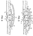
- the switch 11 comprises a push button 25 and a slide button 26.
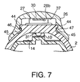
- the push button 25 is made of plastic and has a cylindrical shaft portion 27, elastic stays 28a and 28b projecting from the shaft portion 27 in the forward and rearward directions, an upper projection 30 formed on the upper surface of the shaft portion 27, and a lower projection 31 formed on the underside surface of the shaft portion.
- the shaft portion 27 is slidably engaged in a lateral hole 32 formed in the front case 2.
- the shaft portion 27 has a flange 27a.
- An O-ring 33 is mounted in an annular space 34 formed between the inside wall of the hole 32, the flange 27a, and the shaft portion 27 so that a sealing means is provided for watertightly holding the shaft portion 27.
- Formed on the end of each of the elastic stays 28a and 28b is a leg 35 which is slidably engaged in a hole 36 formed in the front case 2.
- the lower projection 31 contacts with the movable contact 10 so as to make the switch 11.
- a pair of parallel guide rails 44 and guide grooves 45 are formed on the front case 2, longitudinally extending at opposite sides of the push button 25.
- the slide button 26 has a pair of grooves 46 slidably engaged with the rails 44 respectively, and a pair of projections 47 slidably engaged with the grooves 45, respectively.
- the slide button 26 is longitudinally mounted on the front case 2.
- a pushing projection 37 is formed, corresponding to the upper projection 30.
- a front leg 38 abuts on a front stopper 40.
- the sealing device comprises an O-ring. Therefore, the sealing effect is ensured, and the construction is simplified.
Landscapes
- Brushes (AREA)
- Push-Button Switches (AREA)
- Slide Switches (AREA)
Claims (2)
- Interrupteur électrique comportantun bouton à glissière (26) monté de façon coulissante sur un support (2), un bouton-poussoir (25) comportant une partie de tige cylindrique (27) et disposé dans un trou (32) du support de façon à être déplacé dans une direction perpendiculaire à la direction de coulissement du bouton à glissière, un moyen de poussée (37, 30) disposé sur le bouton à glissière et le bouton-poussoir afin de repousser le bouton-poussoir grâce au coulissement du bouton à glissière, un joint torique (33) disposé entre la partie de tige cylindrique du bouton-poussoir et une paroi intérieure du trou du support, un contact mobile (10) en prise avec la partie cylindrique du bouton-poussoir, et un contact fixe (14) destiné à être placé en contact avec le contact mobile de manière à fermer un circuit, dans lequelune paire d'entretoises élastiques (28a, 28b) sont solidaires de la partie de tige cylindrique,une patte (35) de chacune des entretoises vient en prise avec une surface extérieure du support (2), afin de repousser le bouton-poussoir dans une direction opposée à la direction de la poussée,le bouton à glissière (26) est monté de façon coulissante sur la surface extérieure du support par des moyens de guidage (44, 46, 45, 47) et est disposé de façon à recouvrir le bouton-poussoir (25) et les entretoises (28a, 28b).
- Interrupteur selon la revendication 1, dans lequel le moyen de poussée comprend une saillie de poussée (37) formée sur une face inférieure du bouton à glissière (26) ainsi qu'une saillie (30) formée sur une surface de la partie de tige (27).
Applications Claiming Priority (2)
| Application Number | Priority Date | Filing Date | Title |
|---|---|---|---|
| JP10628/94 | 1994-07-25 | ||
| JP1994010628U JP3009365U (ja) | 1994-07-25 | 1994-07-25 | 作動軸変換防水開閉装置 |
Publications (2)
| Publication Number | Publication Date |
|---|---|
| EP0694939A1 EP0694939A1 (fr) | 1996-01-31 |
| EP0694939B1 true EP0694939B1 (fr) | 1998-12-23 |
Family
ID=11755489
Family Applications (1)
| Application Number | Title | Priority Date | Filing Date |
|---|---|---|---|
| EP95305049A Expired - Lifetime EP0694939B1 (fr) | 1994-07-25 | 1995-07-18 | Interrupteur électrique ayant un dispositif d'étanchéité |
Country Status (5)
| Country | Link |
|---|---|
| US (1) | US5575380A (fr) |
| EP (1) | EP0694939B1 (fr) |
| JP (1) | JP3009365U (fr) |
| CN (1) | CN1118509A (fr) |
| DE (1) | DE69506803T2 (fr) |
Cited By (1)
| Publication number | Priority date | Publication date | Assignee | Title |
|---|---|---|---|---|
| US7234187B2 (en) | 1998-09-30 | 2007-06-26 | Church & Dwight Co., Inc. | Electric toothbrush |
Families Citing this family (22)
| Publication number | Priority date | Publication date | Assignee | Title |
|---|---|---|---|---|
| JP2565540Y2 (ja) * | 1992-06-24 | 1998-03-18 | セイコーエプソン株式会社 | 紙排出装置 |
| US5712450A (en) * | 1996-08-05 | 1998-01-27 | Leviton Manufacturing Co., Inc. | Splash guard for wiring devices |
| CH692068A5 (fr) * | 1998-03-05 | 2002-01-15 | Ebauchesfabrik Eta Ag | Boîte de montre munie de moyens de commande. |
| US6038753A (en) * | 1998-04-01 | 2000-03-21 | Btr Sealing Systems Technical Center, Inc. | Swivel sleeve for hand held seal installation tool |
| US6000083A (en) * | 1998-09-30 | 1999-12-14 | Dr. Johns Products, Ltd. | Electric toothbrush |
| JP2001297658A (ja) * | 2000-04-13 | 2001-10-26 | Alps Electric Co Ltd | スライドスイッチ |
| CN100384388C (zh) * | 2002-05-30 | 2008-04-30 | 丘奇和德怀特有限公司 | 电动牙刷及包含电动牙刷的包装盒 |
| US7266855B2 (en) * | 2002-06-04 | 2007-09-11 | Qingping Zhuan | Electric toothbrush |
| US6864448B2 (en) * | 2003-05-14 | 2005-03-08 | Credo Technology Corporation | Power hand tool having a slide switch assembly with a dynamic seal |
| JP2006266415A (ja) * | 2005-03-24 | 2006-10-05 | Fanuc Ltd | 防水・防塵構造 |
| US20080003048A1 (en) * | 2006-06-13 | 2008-01-03 | Karen Glassman | Dentifrice-Dispensing Toothbrush |
| DE102006035341A1 (de) * | 2006-10-12 | 2008-04-17 | Hilti Ag | Handwerkzeugmaschine |
| DE102010026161A1 (de) * | 2010-07-06 | 2012-01-12 | Zweibrüder Optoelectronics Gmbh & Co. Kg | Taschenlampe mit Batteriekartusche |
| JP5619576B2 (ja) * | 2010-11-12 | 2014-11-05 | 富士通コンポーネント株式会社 | コネクタ及びスイッチ |
| CN103280356B (zh) * | 2013-04-15 | 2015-06-10 | 苏州佳世达电通有限公司 | 防水按键及电子装置 |
| US10312039B2 (en) * | 2013-09-10 | 2019-06-04 | Apple Inc. | Generator button for electronic devices |
| US9496696B2 (en) | 2014-09-04 | 2016-11-15 | Leviton Manufacturing Co., Inc. | Weather resistant flip lid cover with improved sealing arrangement |
| CN204792984U (zh) * | 2015-07-06 | 2015-11-18 | 宁波艾森饰品有限公司 | 一种电池盒及应用有该电池盒的项链 |
| CN107301931B (zh) * | 2016-04-15 | 2019-05-17 | 深圳市春宏实业有限公司 | 一种指滑式开关 |
| EP3327741B1 (fr) | 2016-11-24 | 2020-12-23 | Defond Components Limited | Un commutateur électrique pour un dispositif électrique et ensemble d'étanchéité pour un commutateur électrique |
| RU2725039C1 (ru) * | 2019-12-30 | 2020-06-29 | федеральное государственное автономное образовательное учреждение высшего образования "Южно-Уральский государственный университет (национальный исследовательский университет)" | Способ производства биоразлагаемой посуды |
| CN114038700A (zh) * | 2021-11-19 | 2022-02-11 | 深圳市云顶信息技术有限公司 | 电动牙刷 |
Family Cites Families (7)
| Publication number | Priority date | Publication date | Assignee | Title |
|---|---|---|---|---|
| GB958664A (en) * | 1960-07-06 | 1964-05-21 | Telephone Mfg Co Ltd | Improvements in and relating to reciprocating mechanisms |
| US3154659A (en) * | 1961-04-28 | 1964-10-27 | United Carr Inc | Two-way slide switch |
| JPS55155424A (en) * | 1979-05-24 | 1980-12-03 | Omron Tateisi Electronics Co | Dip switch |
| JPS56115817U (fr) * | 1980-02-05 | 1981-09-05 | ||
| US4839483A (en) * | 1986-10-22 | 1989-06-13 | Conair Corporation | Modular watertight switch for use in personal care appliances |
| JPS63304539A (ja) * | 1987-06-04 | 1988-12-12 | Canon Inc | 操作装置 |
| JP2570837Y2 (ja) * | 1992-07-23 | 1998-05-13 | 矢崎総業株式会社 | レバースイッチ |
-
1994
- 1994-07-25 JP JP1994010628U patent/JP3009365U/ja not_active Expired - Lifetime
-
1995
- 1995-07-18 EP EP95305049A patent/EP0694939B1/fr not_active Expired - Lifetime
- 1995-07-18 DE DE69506803T patent/DE69506803T2/de not_active Expired - Fee Related
- 1995-07-24 US US08/506,122 patent/US5575380A/en not_active Expired - Fee Related
- 1995-07-24 CN CN95107588.8A patent/CN1118509A/zh active Pending
Cited By (1)
| Publication number | Priority date | Publication date | Assignee | Title |
|---|---|---|---|---|
| US7234187B2 (en) | 1998-09-30 | 2007-06-26 | Church & Dwight Co., Inc. | Electric toothbrush |
Also Published As
| Publication number | Publication date |
|---|---|
| DE69506803T2 (de) | 1999-05-20 |
| CN1118509A (zh) | 1996-03-13 |
| JP3009365U (ja) | 1995-04-04 |
| DE69506803D1 (de) | 1999-02-04 |
| EP0694939A1 (fr) | 1996-01-31 |
| US5575380A (en) | 1996-11-19 |
Similar Documents
| Publication | Publication Date | Title |
|---|---|---|
| EP0694939B1 (fr) | Interrupteur électrique ayant un dispositif d'étanchéité | |
| US5590434A (en) | Electric toothbrush | |
| JP3841389B2 (ja) | コネクタ嵌合構造 | |
| RU98121840A (ru) | Батарейный источник питания с направляющим ключом и самоблокировкой для портативного дефибриллятора | |
| US7000559B2 (en) | Modularized underwater motive device | |
| US6159019A (en) | Mounting structure for connector for vehicle and method of mounting the same | |
| CN215272479U (zh) | 一种开关及包括其的清洁设备和基站 | |
| CN113438345B (zh) | 手机支架 | |
| EP4023350B1 (fr) | Ensemble de limitation de liaison appliqué dans un aspirateur | |
| EP0392428A2 (fr) | Interrupteur de déclenchement | |
| JPH0729639A (ja) | 電気自動車充電用コネクタ | |
| JP3716457B2 (ja) | 操作ボタン装置 | |
| JP2019022922A (ja) | 手持ち式電動工具 | |
| JPH08111258A (ja) | 電源プラグ | |
| JPH08138793A (ja) | 防滴型ピンコネクタ | |
| US4492429A (en) | Mounting device of optical unit | |
| CN223698073U (zh) | 花洒及淋浴装置 | |
| JPH07295052A (ja) | 操作ボタンの防水構造 | |
| KR0133182Y1 (ko) | 원터치방식에 의한 전원공급 및 이젝트버튼 장치 | |
| JPH07220704A (ja) | 筒形電気機器の電池電源装置 | |
| JPS6133497B2 (fr) | ||
| JPH0135392Y2 (fr) | ||
| KR960008259Y1 (ko) | 온/오프스위치용 콘택트 | |
| JP2021136155A (ja) | トリガスイッチおよび電動装置 | |
| JPH0335620U (fr) |
Legal Events
| Date | Code | Title | Description |
|---|---|---|---|
| PUAI | Public reference made under article 153(3) epc to a published international application that has entered the european phase |
Free format text: ORIGINAL CODE: 0009012 |
|
| AK | Designated contracting states |
Kind code of ref document: A1 Designated state(s): DE FR GB |
|
| 17P | Request for examination filed |
Effective date: 19960711 |
|
| 17Q | First examination report despatched |
Effective date: 19970423 |
|
| GRAG | Despatch of communication of intention to grant |
Free format text: ORIGINAL CODE: EPIDOS AGRA |
|
| GRAG | Despatch of communication of intention to grant |
Free format text: ORIGINAL CODE: EPIDOS AGRA |
|
| GRAH | Despatch of communication of intention to grant a patent |
Free format text: ORIGINAL CODE: EPIDOS IGRA |
|
| GRAH | Despatch of communication of intention to grant a patent |
Free format text: ORIGINAL CODE: EPIDOS IGRA |
|
| GRAA | (expected) grant |
Free format text: ORIGINAL CODE: 0009210 |
|
| AK | Designated contracting states |
Kind code of ref document: B1 Designated state(s): DE FR GB |
|
| PG25 | Lapsed in a contracting state [announced via postgrant information from national office to epo] |
Ref country code: FR Free format text: THE PATENT HAS BEEN ANNULLED BY A DECISION OF A NATIONAL AUTHORITY Effective date: 19981223 |
|
| ET | Fr: translation filed | ||
| REF | Corresponds to: |
Ref document number: 69506803 Country of ref document: DE Date of ref document: 19990204 |
|
| PG25 | Lapsed in a contracting state [announced via postgrant information from national office to epo] |
Ref country code: GB Free format text: LAPSE BECAUSE OF NON-PAYMENT OF DUE FEES Effective date: 19990718 |
|
| PLBE | No opposition filed within time limit |
Free format text: ORIGINAL CODE: 0009261 |
|
| STAA | Information on the status of an ep patent application or granted ep patent |
Free format text: STATUS: NO OPPOSITION FILED WITHIN TIME LIMIT |
|
| 26N | No opposition filed | ||
| GBPC | Gb: european patent ceased through non-payment of renewal fee |
Effective date: 19990718 |
|
| PG25 | Lapsed in a contracting state [announced via postgrant information from national office to epo] |
Ref country code: DE Free format text: LAPSE BECAUSE OF NON-PAYMENT OF DUE FEES Effective date: 20000503 |
|
| REG | Reference to a national code |
Ref country code: FR Ref legal event code: ST |