EP0694945A2 - Rélais électromagnétique miniature et multicontact à usage industriel - Google Patents
Rélais électromagnétique miniature et multicontact à usage industriel Download PDFInfo
- Publication number
- EP0694945A2 EP0694945A2 EP95111786A EP95111786A EP0694945A2 EP 0694945 A2 EP0694945 A2 EP 0694945A2 EP 95111786 A EP95111786 A EP 95111786A EP 95111786 A EP95111786 A EP 95111786A EP 0694945 A2 EP0694945 A2 EP 0694945A2
- Authority
- EP
- European Patent Office
- Prior art keywords
- relay
- movable contacts
- contacts
- coil
- header
- Prior art date
- Legal status (The legal status is an assumption and is not a legal conclusion. Google has not performed a legal analysis and makes no representation as to the accuracy of the status listed.)
- Withdrawn
Links
- 230000005284 excitation Effects 0.000 claims description 4
- 239000011810 insulating material Substances 0.000 claims description 2
- 230000011664 signaling Effects 0.000 claims 1
- 230000035945 sensitivity Effects 0.000 description 3
- 238000003466 welding Methods 0.000 description 2
- 239000003795 chemical substances by application Substances 0.000 description 1
- 230000000881 depressing effect Effects 0.000 description 1
- 238000001746 injection moulding Methods 0.000 description 1
- 230000000670 limiting effect Effects 0.000 description 1
- 238000004519 manufacturing process Methods 0.000 description 1
- 239000000463 material Substances 0.000 description 1
- 230000035939 shock Effects 0.000 description 1
- 229920001169 thermoplastic Polymers 0.000 description 1
- 239000012815 thermoplastic material Substances 0.000 description 1
- 239000004416 thermosoftening plastic Substances 0.000 description 1
Images

Classifications
-
- H—ELECTRICITY
- H01—ELECTRIC ELEMENTS
- H01H—ELECTRIC SWITCHES; RELAYS; SELECTORS; EMERGENCY PROTECTIVE DEVICES
- H01H50/00—Details of electromagnetic relays
- H01H50/54—Contact arrangements
- H01H50/56—Contact spring sets
-
- H—ELECTRICITY
- H01—ELECTRIC ELEMENTS
- H01H—ELECTRIC SWITCHES; RELAYS; SELECTORS; EMERGENCY PROTECTIVE DEVICES
- H01H50/00—Details of electromagnetic relays
- H01H50/02—Bases; Casings; Covers
- H01H50/04—Mounting complete relay or separate parts of relay on a base or inside a case
- H01H50/041—Details concerning assembly of relays
- H01H50/043—Details particular to miniaturised relays
-
- H—ELECTRICITY
- H01—ELECTRIC ELEMENTS
- H01H—ELECTRIC SWITCHES; RELAYS; SELECTORS; EMERGENCY PROTECTIVE DEVICES
- H01H50/00—Details of electromagnetic relays
- H01H50/08—Indicators; Distinguishing marks
-
- H—ELECTRICITY
- H01—ELECTRIC ELEMENTS
- H01H—ELECTRIC SWITCHES; RELAYS; SELECTORS; EMERGENCY PROTECTIVE DEVICES
- H01H50/00—Details of electromagnetic relays
- H01H50/16—Magnetic circuit arrangements
- H01H50/18—Movable parts of magnetic circuits, e.g. armature
- H01H50/24—Parts rotatable or rockable outside coil
- H01H50/26—Parts movable about a knife edge
-
- H—ELECTRICITY
- H01—ELECTRIC ELEMENTS
- H01H—ELECTRIC SWITCHES; RELAYS; SELECTORS; EMERGENCY PROTECTIVE DEVICES
- H01H50/00—Details of electromagnetic relays
- H01H50/16—Magnetic circuit arrangements
- H01H50/18—Movable parts of magnetic circuits, e.g. armature
- H01H50/32—Latching movable parts mechanically
- H01H50/326—Latching movable parts mechanically with manual intervention, e.g. for testing, resetting or mode selection
Definitions
- the present invention relates to a miniature multicontact electromagnetic relay for industrial use.
- the conventional multicontact electromagnetic relay comprise an electromagnetic circuit and a contact system associated with the leads of a base defining the header of the relay.
- the contact system comprises: movable contacts which are switched from normally closed fixed contacts to normally open fixed contacts, all being connected to the header terminals together with the feed leads of the coil.
- the header terminal are of the type inserting in a standard socket.
- the fixed contacts are associated with the corresponding header terminals while the movable contacts are associated with a movable armature which switches the contacts when the coil is exited.
- the movable contacts are electrically connected with their feed terminals fixed on the header by sections of electrical leads having their ends welded to the feed terminals on the other side.
- the electrical leads inside the conventional miniature relays for industrial use besides occupying considerable space, entail a welding operation to respectively the movable contacts and to the fixed feed contacts with a considerable increase of production costs of the relay.
- the electrical leads even though flexible, influence the correct motion of the armature and therefore the switching of the movable contacts.
- the space occupied by the electrical leads entails a reduction of the coil size given a certain size of the conventional relay and therefore a reduction of the sensitivity of the electromagnetic relay.
- the aim of the present invention is to eliminate the above mentioned inconveniences by providing a multicontact electromagnetic relay for industrial use having a header interchangeable with that of conventional relays and which is composed of a reduced number of components with respect of the comparable conventional relays.
- an important object of the invention is to provide a multicontact electromagnetic relay for industrial use having no electrical leads inside it for connecting the movable contacts with the relay feed terminals and therefore having an easy assembly.
- a further aim of the invention is to provide a multicontact electromagnetic relay for industrial use which has no electrical leads inside it and therefore allows the use of a larger coil with respect of conventional relays of the same size.
- Still a further aim of the invention is to provide a multicontact electromagnetic relay for industrial use of lower cost, thanks to the simplified structure and assembly, and of greater power and sensitivity compared to conventional relays of the same size.
- a multicontact electromagnetic relay for industrial use comprising an electromagnetic circuit defined by a coil, a U bolt, an armature movable on said U bolt in contrast and by the action of elastic means, and movable contacts actuated by said armature for switching from normally closed fixed contacts to normally open fixed contacts defining the header of said relay together with feed terminals of said movable contacts and to the feed terminals of said coil, characterized in that each of said feed terminals of said movable contacts comprises elastic means for electrically feed said movable contacts and for applying a preset force on said movable contacts adapted to define an optimal contact pressure with said normally closed fixed contacts.
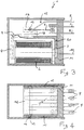
- the multicontact electromagnetic relay for industrial use comprises an electromagnetic circuit defined by a coil 2, a U bolt 3, an armature 4 movable on the bolt 3 in contrast and by the action of elastic means, for example a spring 5 having an end fixed to the bolt 3.
- the electromagnetic circuit further comprises: a contact system, defined by movable contacts 6 which are actuated by the armature 4 for switching them from normally closed fixed contacts 7 to normally open fixed contacts 8; feed terminals 9 for feeding the movable contacts; and coil feed terminals 10.
- the assembly of the normally closed and normally open fixed contacts 7 and 8, of the feed terminals 9 of the movable contacts and of the coil feed terminals 10 defines the header 11 of the relay.
- each of the movable contact feed terminals 9 is provided with elastic means, globally designated by the reference numeral 12, for electrically feed the movable contacts 6 and for applying a preset force adapted to define an optimal contact pressure between the movable contacts 6 and the normally closed fixed contacts 7.
- the elastic means 12 is defined by an elastically yielding portion 13 of the feed terminals 9.
- the movable contacts 6 are electrically fed and there is an elastic preset force adapted to maintain the movable contacts against the normally closed fixed contacts 7 with an optimal contact pressure.
- the elastic forces acting on the movable contacts 6 and those acting on the armature 4 are distinct, thereby ensuring a regular and optimal operation of the relay independently from external agents such as shocks, vibrations and similar.
- the mobile contacts 6 are also connected with a support member 14, for example provided by co-injection molding in thermoplastic insulating material, or by two plates in thermoplastic material welded together, by ultrasonic welding or any other suitable system.
- the support member 14 has hinge means for its controlled rotation about an axis perpendicular to the coil 2.
- the hinge means is defined by two pivots 15 arranged coaxially and spaced apart and adapted to engage in respective seats 16 provided on the two opposed walls 17 of the header 11.
- the two walls 17 also act as guides for the introduction of the cover 18 above the header 11, thereby making the connection of the two elements easier.
- the support member 14 has a domed control portion 18, facing the armature 4, for moving the support member about the rotation axis defined by the pivots 15.
- the domed portion 18 is arranged between the support member 14 and the header 11, with respect to the rotation axis of the support member 14.
- the elastic portions 13 of feed terminals 9 engage the movable contacts 6 in a region comprised between the hinge axis of the support member and the normally closed and normally open fixed contact 7 and 8.
- an insulating case 20 is provided and conveniently defines a support region of the armature 4 when the coil is not excited.
- the structure of the miniature multicontact electromagnetic relay for industrial use allows to arrange inside it a manual switch member, of the movable contacts from the normally closed fixed contacts to the normally open fixed contacts 7 and 8, such manual switch member acting directly on the armature 4.
- the coil being arranged inside the relay with its axis substantially perpendicular to the header 11, the manual switching operation is possible by simply depressing the button 25 adapted to displace the armature.
- the same relay structure also allows to visibly signal the excitation of the relay without further elements as in conventional relays, by simply providing the support member 14 with a portion 26 extending to the opposite side of the header 11 to the window 27 provided on the cover 18.
- the excitation of the relay will bring the colored end of the portion 26 at said window 27 making it visible.
- the above described arrangement of the coil 2 allows to increase its longitudinal and radial extension giving the relay more power and sensitivity with respect of conventional relays of the same external size.
- the movable contacts 6 are pressed against the normally closed fixed contacts 7 by the elastic portions 13 of the feed terminals 9 which provide the passage of current and the optimal contact pressure on the normally closed fixed contacts.
- the armature 4 of the electromagnetic circuit acts on the support member 14 of the movable contacts 6, making the support member rotate about its rotation axis and overcoming the reaction of the elastic portions 13 of the feed terminals 9.
- the movable contacts switch from the normally closed fixed contacts to the normally open fixed contacts with the selected pressure on the normally open fixed contacts.
- the miniature multicontact electromagnetic relay for industrial use is also particularly convenient because it is constituted by an extremely reduced number of elements, because the elastic forces acting on the movable contacts are distinct and independent from those acting on the armature, and because the excitation of the relay can be optically signalled without further elements.
- the materials employed, as well as the dimensions, may be any according to the specific needs and the state of the art.
Landscapes
- Physics & Mathematics (AREA)
- Electromagnetism (AREA)
- Relay Circuits (AREA)
- Switch Cases, Indication, And Locking (AREA)
Applications Claiming Priority (2)
| Application Number | Priority Date | Filing Date | Title |
|---|---|---|---|
| IT94MI000570U IT233985Y1 (it) | 1994-07-29 | 1994-07-29 | Rele' elettromagnetico pluricontatto miniatura per usi industriali |
| ITMI940570 | 1994-07-29 |
Publications (2)
| Publication Number | Publication Date |
|---|---|
| EP0694945A2 true EP0694945A2 (fr) | 1996-01-31 |
| EP0694945A3 EP0694945A3 (fr) | 1999-03-03 |
Family
ID=11368365
Family Applications (1)
| Application Number | Title | Priority Date | Filing Date |
|---|---|---|---|
| EP95111786A Withdrawn EP0694945A3 (fr) | 1994-07-29 | 1995-07-26 | Rélais électromagnétique miniature et multicontact à usage industriel |
Country Status (3)
| Country | Link |
|---|---|
| US (1) | US5680082A (fr) |
| EP (1) | EP0694945A3 (fr) |
| IT (1) | IT233985Y1 (fr) |
Cited By (3)
| Publication number | Priority date | Publication date | Assignee | Title |
|---|---|---|---|---|
| EP1253612A3 (fr) * | 2001-04-26 | 2005-04-20 | Tyco Electronics AMP GmbH | Relais de commutation avec indicateur de position de commutation |
| EP1471556A3 (fr) * | 2003-04-24 | 2006-07-05 | Omron Corporation | Relais électromagnétique |
| CN103681118A (zh) * | 2012-09-17 | 2014-03-26 | 施耐德电器工业公司 | 用于切换电磁继电器的工具及方法 |
Families Citing this family (9)
| Publication number | Priority date | Publication date | Assignee | Title |
|---|---|---|---|---|
| US6714106B1 (en) | 2002-01-04 | 2004-03-30 | Reliance Controls Corporation | Switch having integral remote actuating device |
| JP5085754B2 (ja) * | 2011-03-14 | 2012-11-28 | オムロン株式会社 | 電磁継電器 |
| JP4883232B1 (ja) * | 2011-03-14 | 2012-02-22 | オムロン株式会社 | 電磁継電器 |
| WO2012124174A1 (fr) * | 2011-03-14 | 2012-09-20 | オムロン株式会社 | Relais électromagnétique |
| JP6056264B2 (ja) * | 2012-08-24 | 2017-01-11 | オムロン株式会社 | 電磁石装置およびそれを用いた電磁継電器 |
| JP6043173B2 (ja) * | 2012-12-07 | 2016-12-14 | 富士通コンポーネント株式会社 | 電磁継電器 |
| KR200474510Y1 (ko) * | 2013-02-18 | 2014-09-23 | 엘에스산전 주식회사 | 전자 개폐 장치 |
| JP2014165152A (ja) * | 2013-02-27 | 2014-09-08 | Fujitsu Component Ltd | 電磁継電器 |
| JP6263904B2 (ja) * | 2013-08-23 | 2018-01-24 | オムロン株式会社 | 電磁石装置およびこれを用いた電磁継電器 |
Family Cites Families (12)
| Publication number | Priority date | Publication date | Assignee | Title |
|---|---|---|---|---|
| US2563830A (en) * | 1945-11-07 | 1951-08-14 | Monitor Controller Co | Radio-frequency contactor |
| FR1056593A (fr) * | 1952-05-16 | 1954-03-01 | équipage de contacts commutateurs à glissement et écartement combinés | |
| DE1166893B (de) * | 1961-06-08 | 1964-04-02 | Siemens Ag | Kontaktanordnung fuer elektrische Schaltgeraete, insbesondere fuer Relais |
| FR1403781A (fr) * | 1964-05-08 | 1965-06-25 | Electro Securit Soc | Perfectionnements aux relais électriques |
| DE2118633B2 (de) * | 1970-04-22 | 1974-10-24 | Matsushita Electric Works Ltd., Kadoma, Osaka (Japan) | Klappankerschütz mit Wechselkontaktsätzen |
| US3733568A (en) * | 1971-09-30 | 1973-05-15 | Essex | Push button relay |
| AU5418973A (en) * | 1972-04-15 | 1974-10-10 | The Lucas Electrical Company Limited | Electrical relays |
| DE2805020C2 (de) * | 1978-02-06 | 1980-02-14 | H. Kuhnke Gmbh Kg, 2427 Malente | Elektrisches Schaltgerat |
| JPS63149039U (fr) * | 1987-03-20 | 1988-09-30 | ||
| JPH0723875Y2 (ja) * | 1987-09-04 | 1995-05-31 | オムロン株式会社 | 動作表示付リレー |
| US4758809A (en) * | 1987-09-17 | 1988-07-19 | Potter And Brumfield Inc. | Electromagnetic relay having a multifunction retaining spring |
| JPH0346728A (ja) * | 1989-07-13 | 1991-02-28 | Omron Corp | 電磁継電器 |
-
1994
- 1994-07-29 IT IT94MI000570U patent/IT233985Y1/it active IP Right Grant
-
1995
- 1995-07-26 EP EP95111786A patent/EP0694945A3/fr not_active Withdrawn
- 1995-07-27 US US08/508,070 patent/US5680082A/en not_active Expired - Fee Related
Cited By (4)
| Publication number | Priority date | Publication date | Assignee | Title |
|---|---|---|---|---|
| EP1253612A3 (fr) * | 2001-04-26 | 2005-04-20 | Tyco Electronics AMP GmbH | Relais de commutation avec indicateur de position de commutation |
| EP1471556A3 (fr) * | 2003-04-24 | 2006-07-05 | Omron Corporation | Relais électromagnétique |
| CN103681118A (zh) * | 2012-09-17 | 2014-03-26 | 施耐德电器工业公司 | 用于切换电磁继电器的工具及方法 |
| CN103681118B (zh) * | 2012-09-17 | 2016-01-20 | 施耐德电器工业公司 | 用于切换电磁继电器的工具及方法 |
Also Published As
| Publication number | Publication date |
|---|---|
| EP0694945A3 (fr) | 1999-03-03 |
| ITMI940570U1 (it) | 1996-01-29 |
| US5680082A (en) | 1997-10-21 |
| IT233985Y1 (it) | 2000-02-16 |
| ITMI940570V0 (it) | 1994-07-29 |
Similar Documents
| Publication | Publication Date | Title |
|---|---|---|
| US5160910A (en) | Electromagnetic relay | |
| US6150909A (en) | Electromagnetic switching device | |
| US4461968A (en) | Piezoelectric relay with magnetic detent | |
| KR101016212B1 (ko) | 마이크로 스위치 | |
| KR102713597B1 (ko) | 마이크로 스위치가 구비된 자기 래칭 릴레이 | |
| US5680082A (en) | Miniature multicontact electromagnetic relay for industrial use | |
| US4772807A (en) | Electric control device for controlling displacement of an element between two predetermined positions | |
| KR102093017B1 (ko) | 전자기 릴레이 | |
| EP2133898B1 (fr) | Cale isolante sans outil | |
| US4544811A (en) | Electric switch | |
| US6034585A (en) | Switching device | |
| US5601183A (en) | Two-pole make-before-break switch | |
| JPH0724176B2 (ja) | 機械電気的組み合わせ連動機構 | |
| CA2012457C (fr) | Relais electromagnetique polarise | |
| JP2000510277A (ja) | 接続導体付き低電圧用遮断器 | |
| US3448226A (en) | Compact electrical contact block with electrically isolated bridging contacts | |
| US4254391A (en) | Split armature relay | |
| US3249714A (en) | Magnetically operable switching device | |
| CN210722810U (zh) | 双电源转换机构及具有该双电源转换机构的供电电源 | |
| US3693120A (en) | Electromagnetic relay | |
| CN215680442U (zh) | 负载开关 | |
| US6046418A (en) | Drive system for switch, especially relay | |
| CN117476328A (zh) | 电磁铁装置 | |
| KR20020083441A (ko) | 스위칭 상태 디스플레이부를 구비한 스위치 릴레이 | |
| KR100298331B1 (ko) | 전자접촉기의보조가동접촉자어셈블리 |
Legal Events
| Date | Code | Title | Description |
|---|---|---|---|
| PUAI | Public reference made under article 153(3) epc to a published international application that has entered the european phase |
Free format text: ORIGINAL CODE: 0009012 |
|
| AK | Designated contracting states |
Kind code of ref document: A2 Designated state(s): AT BE CH DE DK ES FR GB GR IE LI LU MC NL PT SE |
|
| PUAL | Search report despatched |
Free format text: ORIGINAL CODE: 0009013 |
|
| AK | Designated contracting states |
Kind code of ref document: A3 Designated state(s): AT BE CH DE DK ES FR GB GR IE LI LU MC NL PT SE |
|
| STAA | Information on the status of an ep patent application or granted ep patent |
Free format text: STATUS: THE APPLICATION IS DEEMED TO BE WITHDRAWN |
|
| 18D | Application deemed to be withdrawn |
Effective date: 19990904 |