EP0695019A1 - Elektromachinerotor, insbesondere für einen Elektromotor, der eine Wärmkraftmaschine eines Fahrzeugs anfählt und Vorrichtung für seine Herstellung - Google Patents
Elektromachinerotor, insbesondere für einen Elektromotor, der eine Wärmkraftmaschine eines Fahrzeugs anfählt und Vorrichtung für seine Herstellung Download PDFInfo
- Publication number
- EP0695019A1 EP0695019A1 EP95111328A EP95111328A EP0695019A1 EP 0695019 A1 EP0695019 A1 EP 0695019A1 EP 95111328 A EP95111328 A EP 95111328A EP 95111328 A EP95111328 A EP 95111328A EP 0695019 A1 EP0695019 A1 EP 0695019A1
- Authority
- EP
- European Patent Office
- Prior art keywords
- conductors
- slots
- conductor
- slot
- diameter
- Prior art date
- Legal status (The legal status is an assumption and is not a legal conclusion. Google has not performed a legal analysis and makes no representation as to the accuracy of the status listed.)
- Granted
Links
- 238000002485 combustion reaction Methods 0.000 title claims description 4
- 238000000034 method Methods 0.000 title claims 3
- 238000004519 manufacturing process Methods 0.000 title description 2
- 239000004020 conductor Substances 0.000 claims abstract description 50
- 238000003475 lamination Methods 0.000 claims abstract description 6
- 230000003247 decreasing effect Effects 0.000 claims abstract 3
- 230000002093 peripheral effect Effects 0.000 description 3
- XEEYBQQBJWHFJM-UHFFFAOYSA-N Iron Chemical compound [Fe] XEEYBQQBJWHFJM-UHFFFAOYSA-N 0.000 description 2
- 230000004907 flux Effects 0.000 description 2
- 230000005291 magnetic effect Effects 0.000 description 2
- 239000007858 starting material Substances 0.000 description 2
- 230000004308 accommodation Effects 0.000 description 1
- 230000007423 decrease Effects 0.000 description 1
- 239000003302 ferromagnetic material Substances 0.000 description 1
- 239000011810 insulating material Substances 0.000 description 1
- 229910052742 iron Inorganic materials 0.000 description 1
- 238000003754 machining Methods 0.000 description 1
- 238000005259 measurement Methods 0.000 description 1
- 230000003068 static effect Effects 0.000 description 1
Images

Classifications
-
- H—ELECTRICITY
- H02—GENERATION; CONVERSION OR DISTRIBUTION OF ELECTRIC POWER
- H02K—DYNAMO-ELECTRIC MACHINES
- H02K3/00—Details of windings
- H02K3/46—Fastening of windings on the stator or rotor structure
- H02K3/48—Fastening of windings on the stator or rotor structure in slots
-
- H—ELECTRICITY
- H02—GENERATION; CONVERSION OR DISTRIBUTION OF ELECTRIC POWER
- H02K—DYNAMO-ELECTRIC MACHINES
- H02K15/00—Processes or apparatus specially adapted for manufacturing, assembling, maintaining or repairing of dynamo-electric machines
- H02K15/20—Shaping or compacting conductors or winding heads after the installation of the winding in the cores or machines; Applying fastening means on winding heads
- H02K15/22—Shaping or compacting conductors in slots or around salient poles
-
- H—ELECTRICITY
- H02—GENERATION; CONVERSION OR DISTRIBUTION OF ELECTRIC POWER
- H02K—DYNAMO-ELECTRIC MACHINES
- H02K3/00—Details of windings
- H02K3/04—Windings characterised by the conductor shape, form or construction, e.g. with bar conductors
- H02K3/12—Windings characterised by the conductor shape, form or construction, e.g. with bar conductors arranged in slots
Definitions
- the present invention relates to a rotor of an electrical machine, in particular of a direct current electric motor for starting the internal combustion engine of a motor vehicle.
- the invention relates to a rotor comprising a stack of laminations, in the periphery of which are provided radial slots, each of which accommodates a group of insulated electrical conductors and has a mouth portion having a width which corresponds substantially to the diameter of a conductor and accommodates the radially outermost conductor of the group.
- these slots are produced with a depth in the radial direction which is markedly greater than the depth which is strictly necessary for accommodating the corresponding electrical conductors.
- the edges of the slots are thus plastically deformed, usually during stamping operations performed at a given pitch along the slots such that the plastically deformed edges prevent the conductors from escaping from the slots.
- this solution implies that the slots are arranged with a radial depth which is substantially greater than the measurement which would strictly be necessary for guaranteeing the accommodation of the conductors. This is to the detriment of the intensity of the magnetic flux which affects the operation of the rotor.
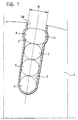
- each slot 2 has opposite recesses 4 and the outermost conductor of each slot 2 is deformed plastically and has a flattened portion, the opposite ends of which engage in the recesses 4, preventing the conductors 3 from escaping from the slot 2.
- the slots 2 have a constant width which is substantially equal to the diameter of the conductors 3, except in correspondence with the recesses 4.
- the height or depth of the slots is substantially equal to the sum of the diameters of the conductors 3 accommodated therein.
- the object of the present invention is to provide a rotor of the above-mentioned type which, with respect to what has been described above, maintaining constant the diameter of the rotor, the number of the slots and the number and diameter of the conductors per slot, enables the minimum width of the part made of ferromagnetic material to be increased between slots and the width in the peripheral direction of the teeth defined between pairs of adjacent slots, ultimately obtaining - whilst the other geometrical conditions remain the same - an increase in the cross-section of the rotor which is operationally affected by the magnetic flux and thus an increase in the torque provided by the starter motor, whilst the number of revolutions remains the same.
- the present invention achieves the above objects by means of a rotor of the type specified above having the characteristics mentioned specifically in the following claims.
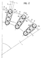
- the radial slots 2 (the surfaces of which can be covered with an insulating material according to the prior art) have the mouth portion 2a comprising two opposite projections 4' between which is a distance W substantially corresponding to the diameter of a conductor 3.
- the portion of the radial slots 2 inward of the mouth portion 2a has a width in the peripheral sense which is greater than the diameter of a conductor 3; this portion decreases radially until, at the base of the slot 2, it is substantially equal to the diameter of a conductor 3.
- the overall depth of the slots 2 is less than the sum of the diameters of the conductors 3 accommodated therein (four in the case of Figures 2 and 3), for which reason a part of the outermost conductor emerges from the slot over almost half the diameter.
- the conductors 3 are plastically deformed, assuming the flattened shape of Figure 3.
- the conductors 3 are deformed progressively more markedly from the interior towards the exterior of the slots 2 and have cross-sections which are increasingly more flattened.
- the opposite ends of the flattened portions of the outermost conductors engage below the opposite projections 4' so as to prevent the conductors 3 emerging either in static conditions or in the more difficult dynamic conditions when the rotor is operating.
- a peripheral layer of machining allowance (10 in Figure 2) can then be removed before the armature and the inductor are assembled to form the starter motor.
- the minimum width of the iron between slots increases by approximately 15%
- the minimum diameter on which the conductors 3 act increases by approximately 10% and it has been confirmed in experiments that the starting torque increases by approximately 10%.
Landscapes
- Engineering & Computer Science (AREA)
- Power Engineering (AREA)
- Manufacturing & Machinery (AREA)
- Induction Machinery (AREA)
- Manufacture Of Motors, Generators (AREA)
- Iron Core Of Rotating Electric Machines (AREA)
- Insulation, Fastening Of Motor, Generator Windings (AREA)
- Windings For Motors And Generators (AREA)
Applications Claiming Priority (2)
| Application Number | Priority Date | Filing Date | Title |
|---|---|---|---|
| ITTO940624 | 1994-07-27 | ||
| IT94TO000624A IT1266896B1 (it) | 1994-07-27 | 1994-07-27 | Rotore di macchina elettrica, in particolare di un motore elettrico per l'avviamento del motore a combustione interna di una autoveicolo e |
Publications (2)
| Publication Number | Publication Date |
|---|---|
| EP0695019A1 true EP0695019A1 (de) | 1996-01-31 |
| EP0695019B1 EP0695019B1 (de) | 1997-09-24 |
Family
ID=11412708
Family Applications (1)
| Application Number | Title | Priority Date | Filing Date |
|---|---|---|---|
| EP95111328A Expired - Lifetime EP0695019B1 (de) | 1994-07-27 | 1995-07-19 | Elektromachinerotor, insbesondere für einen Elektromotor, der eine Wärmkraftmaschine eines Fahrzeugs anfählt und Vorrichtung für seine Herstellung |
Country Status (4)
| Country | Link |
|---|---|
| EP (1) | EP0695019B1 (de) |
| DE (1) | DE69500756T2 (de) |
| ES (1) | ES2109040T3 (de) |
| IT (1) | IT1266896B1 (de) |
Cited By (13)
| Publication number | Priority date | Publication date | Assignee | Title |
|---|---|---|---|---|
| WO1997045920A1 (en) * | 1996-05-29 | 1997-12-04 | Asea Brown Boveri Ab | A conductor for high-voltage windings, and a process for preparing such conductor |
| WO1997045930A1 (en) * | 1996-05-29 | 1997-12-04 | Asea Brown Boveri Ab | Conductor for high-voltage windings and a rotating electric machine comprising a winding including the conductor |
| US6226163B1 (en) | 1996-12-17 | 2001-05-01 | Asea Brown Boveri Ab | Device and method relating to protection of an object against over-currents comprising over-current reduction |
| WO2002031946A1 (de) * | 2000-10-07 | 2002-04-18 | Robert Bosch Gmbh | Rotorkörper und verfahren zur herstellung von rotorkörpern |
| WO2007125234A1 (fr) * | 2006-05-02 | 2007-11-08 | Valeo Equipements Electriques Moteur | Procédé de montage d'un enroulement d'un bobinage de stator dans un paquet de tôles |
| FR2923662A1 (fr) * | 2007-11-13 | 2009-05-15 | Valeo Equip Electr Moteur | Machine electrique tournante pour vehicule automobile. |
| CN102904361A (zh) * | 2011-07-26 | 2013-01-30 | 通用汽车环球科技运作有限责任公司 | 用于电机的励磁线圈 |
| WO2014174658A1 (ja) * | 2013-04-26 | 2014-10-30 | 三菱電機株式会社 | 電機子コイル及びその製造方法 |
| US20150288231A1 (en) * | 2014-04-04 | 2015-10-08 | Solar Turbines Incorporated | Electric motor with symmetric cooling |
| WO2015159032A1 (fr) * | 2014-04-17 | 2015-10-22 | Valeo Equipements Electriques Moteur | Procede de realisation d'un stator de machine electrique comprenant une etape de deformation des conducteurs et stator correspondant |
| FR3020215A1 (fr) * | 2014-04-17 | 2015-10-23 | Valeo Equip Electr Moteur | Procede de realisation d'un stator bobine de machine electrique muni d'un isolant d'encoche continu et stator correspondant |
| FR3023080A1 (fr) * | 2014-06-30 | 2016-01-01 | Valeo Equip Electr Moteur | Induit de machine electrique tournante a remplissage d'encoches optimise |
| EP2963773A3 (de) * | 2014-07-01 | 2016-10-12 | Victory Industrial Corporation | Fahrzeugwechselstromgenerator |
Families Citing this family (30)
| Publication number | Priority date | Publication date | Assignee | Title |
|---|---|---|---|---|
| AU718706B2 (en) | 1996-05-29 | 2000-04-20 | Abb Ab | A DC transformer/reactor |
| EP0888661B1 (de) | 1996-05-29 | 2003-11-19 | Abb Ab | Hochspannung erzeugender wechselstromgenerator |
| US6972505B1 (en) | 1996-05-29 | 2005-12-06 | Abb | Rotating electrical machine having high-voltage stator winding and elongated support devices supporting the winding and method for manufacturing the same |
| SE510192C2 (sv) | 1996-05-29 | 1999-04-26 | Asea Brown Boveri | Förfarande och kopplingsarrangemang för att minska problem med tredjetonsströmmar som kan uppstå vid generator - och motordrift av växelströmsmaskiner kopplade till trefas distributions- eller transmissionsnät |
| SE9602079D0 (sv) | 1996-05-29 | 1996-05-29 | Asea Brown Boveri | Roterande elektriska maskiner med magnetkrets för hög spänning och ett förfarande för tillverkning av densamma |
| SE509072C2 (sv) | 1996-11-04 | 1998-11-30 | Asea Brown Boveri | Anod, anodiseringsprocess, anodiserad tråd och användning av sådan tråd i en elektrisk anordning |
| SE510422C2 (sv) | 1996-11-04 | 1999-05-25 | Asea Brown Boveri | Magnetplåtkärna för elektriska maskiner |
| SE512917C2 (sv) | 1996-11-04 | 2000-06-05 | Abb Ab | Förfarande, anordning och kabelförare för lindning av en elektrisk maskin |
| SE515843C2 (sv) | 1996-11-04 | 2001-10-15 | Abb Ab | Axiell kylning av rotor |
| SE9704431D0 (sv) | 1997-02-03 | 1997-11-28 | Asea Brown Boveri | Effektreglering av synkronmaskin |
| SE9704412D0 (sv) | 1997-02-03 | 1997-11-28 | Asea Brown Boveri | Krafttransformator/reaktor |
| SE9704421D0 (sv) | 1997-02-03 | 1997-11-28 | Asea Brown Boveri | Seriekompensering av elektrisk växelströmsmaskin |
| SE508544C2 (sv) | 1997-02-03 | 1998-10-12 | Asea Brown Boveri | Förfarande och anordning för montering av en stator -lindning bestående av en kabel. |
| SE9704423D0 (sv) | 1997-02-03 | 1997-11-28 | Asea Brown Boveri | Roterande elektrisk maskin med spolstöd |
| SE9704413D0 (sv) | 1997-02-03 | 1997-11-28 | Asea Brown Boveri | Krafttransformator/reaktor |
| SE510452C2 (sv) | 1997-02-03 | 1999-05-25 | Asea Brown Boveri | Transformator med spänningsregleringsorgan |
| SE508543C2 (sv) | 1997-02-03 | 1998-10-12 | Asea Brown Boveri | Hasplingsanordning |
| SE9704422D0 (sv) | 1997-02-03 | 1997-11-28 | Asea Brown Boveri | Ändplatta |
| SE9704427D0 (sv) | 1997-02-03 | 1997-11-28 | Asea Brown Boveri | Infästningsanordning för elektriska roterande maskiner |
| SE513083C2 (sv) | 1997-09-30 | 2000-07-03 | Abb Ab | Synkronkompensatoranläggning jämte användning av dylik samt förfarande för faskompensation i ett högspänt kraftfält |
| SE513555C2 (sv) | 1997-11-27 | 2000-10-02 | Abb Ab | Förfarande för applicering av ett rörorgan i ett utrymme i en roterande elektrisk maskin och roterande elektrisk maskin enligt förfarandet |
| BR9815420A (pt) | 1997-11-28 | 2001-07-17 | Abb Ab | Método e dispositivo para controlar o fluxo magnético com um enrolamento auxiliar em uma máquina rotativa de alta voltagem de corrente alternada |
| GB2331853A (en) | 1997-11-28 | 1999-06-02 | Asea Brown Boveri | Transformer |
| GB2331858A (en) | 1997-11-28 | 1999-06-02 | Asea Brown Boveri | A wind power plant |
| GB2331867A (en) | 1997-11-28 | 1999-06-02 | Asea Brown Boveri | Power cable termination |
| US6801421B1 (en) | 1998-09-29 | 2004-10-05 | Abb Ab | Switchable flux control for high power static electromagnetic devices |
| SE516002C2 (sv) | 2000-03-01 | 2001-11-05 | Abb Ab | Roterande elektrisk maskin samt förfarande för framställning av en statorlindning |
| US6885273B2 (en) | 2000-03-30 | 2005-04-26 | Abb Ab | Induction devices with distributed air gaps |
| SE516442C2 (sv) | 2000-04-28 | 2002-01-15 | Abb Ab | Stationär induktionsmaskin och kabel därför |
| DE102018104844A1 (de) * | 2018-03-02 | 2019-09-05 | Aumann Espelkamp Gmbh | Verfahren und Vorrichtung zum Herstellen einer Anordnung für eine Spule mit einer verteilten Spulenwicklung einer elektrodynamischen Maschine, Anordnung und Spule |
Citations (4)
| Publication number | Priority date | Publication date | Assignee | Title |
|---|---|---|---|---|
| DE572619C (de) * | 1929-10-29 | 1933-03-18 | Bbc Brown Boveri & Cie | Verfahren zum Befestigen eines in eine offene Nut eines Kurzschlusslaeufers eingefuehrten blanken Kurzschlussstabes |
| FR1573177A (de) * | 1968-04-11 | 1969-07-04 | ||
| FR2415385A1 (fr) * | 1978-01-18 | 1979-08-17 | Bosch Gmbh Robert | Rotor pour une machine electrique |
| DE3347195A1 (de) * | 1982-12-27 | 1984-07-05 | Hitachi, Ltd., Tokio/Tokyo | Anker fuer eine elektrische rotationsmaschine |
-
1994
- 1994-07-27 IT IT94TO000624A patent/IT1266896B1/it active IP Right Grant
-
1995
- 1995-07-19 EP EP95111328A patent/EP0695019B1/de not_active Expired - Lifetime
- 1995-07-19 ES ES95111328T patent/ES2109040T3/es not_active Expired - Lifetime
- 1995-07-19 DE DE69500756T patent/DE69500756T2/de not_active Expired - Lifetime
Patent Citations (4)
| Publication number | Priority date | Publication date | Assignee | Title |
|---|---|---|---|---|
| DE572619C (de) * | 1929-10-29 | 1933-03-18 | Bbc Brown Boveri & Cie | Verfahren zum Befestigen eines in eine offene Nut eines Kurzschlusslaeufers eingefuehrten blanken Kurzschlussstabes |
| FR1573177A (de) * | 1968-04-11 | 1969-07-04 | ||
| FR2415385A1 (fr) * | 1978-01-18 | 1979-08-17 | Bosch Gmbh Robert | Rotor pour une machine electrique |
| DE3347195A1 (de) * | 1982-12-27 | 1984-07-05 | Hitachi, Ltd., Tokio/Tokyo | Anker fuer eine elektrische rotationsmaschine |
Non-Patent Citations (1)
| Title |
|---|
| R. KRETZCHMANN: ""Gesichtspunkte für die herstellung und auswahl von explosionsgeschützten drehstrom-asynchronmotoren"", DEUTSCHE ELEKTROTECHNIK, vol. 13, no. 5, BERLIN, pages 165 - 168 * |
Cited By (20)
| Publication number | Priority date | Publication date | Assignee | Title |
|---|---|---|---|---|
| WO1997045920A1 (en) * | 1996-05-29 | 1997-12-04 | Asea Brown Boveri Ab | A conductor for high-voltage windings, and a process for preparing such conductor |
| WO1997045930A1 (en) * | 1996-05-29 | 1997-12-04 | Asea Brown Boveri Ab | Conductor for high-voltage windings and a rotating electric machine comprising a winding including the conductor |
| US6226163B1 (en) | 1996-12-17 | 2001-05-01 | Asea Brown Boveri Ab | Device and method relating to protection of an object against over-currents comprising over-current reduction |
| WO2002031946A1 (de) * | 2000-10-07 | 2002-04-18 | Robert Bosch Gmbh | Rotorkörper und verfahren zur herstellung von rotorkörpern |
| WO2007125234A1 (fr) * | 2006-05-02 | 2007-11-08 | Valeo Equipements Electriques Moteur | Procédé de montage d'un enroulement d'un bobinage de stator dans un paquet de tôles |
| FR2900773A1 (fr) * | 2006-05-02 | 2007-11-09 | Valeo Equip Electr Moteur | Procede de montage d'un enroulement d'un bobinage de stator dans un paquet de toles |
| FR2923662A1 (fr) * | 2007-11-13 | 2009-05-15 | Valeo Equip Electr Moteur | Machine electrique tournante pour vehicule automobile. |
| CN102904361A (zh) * | 2011-07-26 | 2013-01-30 | 通用汽车环球科技运作有限责任公司 | 用于电机的励磁线圈 |
| CN102904361B (zh) * | 2011-07-26 | 2015-09-30 | 通用汽车环球科技运作有限责任公司 | 用于电机的励磁线圈 |
| WO2014174658A1 (ja) * | 2013-04-26 | 2014-10-30 | 三菱電機株式会社 | 電機子コイル及びその製造方法 |
| US9960650B2 (en) | 2013-04-26 | 2018-05-01 | Mitsubishi Electric Corporation | Armature coil and method of manufacturing the same |
| US11316395B2 (en) | 2013-04-26 | 2022-04-26 | Mitsubishi Electric Corporation | Method of manufacturing armature coil |
| US10644556B2 (en) | 2013-04-26 | 2020-05-05 | Mitsubishi Electric Corporation | Method of manufacturing armature coil |
| US20150288231A1 (en) * | 2014-04-04 | 2015-10-08 | Solar Turbines Incorporated | Electric motor with symmetric cooling |
| WO2015153081A1 (en) * | 2014-04-04 | 2015-10-08 | Solar Turbines Incorporated | Electric motor with symmetric cooling |
| FR3020196A1 (fr) * | 2014-04-17 | 2015-10-23 | Valeo Equip Electr Moteur | Procede de realisation d'un stator de machine electrique comprenant une etape de deformation des conducteurs et stator correspondant |
| FR3020215A1 (fr) * | 2014-04-17 | 2015-10-23 | Valeo Equip Electr Moteur | Procede de realisation d'un stator bobine de machine electrique muni d'un isolant d'encoche continu et stator correspondant |
| WO2015159032A1 (fr) * | 2014-04-17 | 2015-10-22 | Valeo Equipements Electriques Moteur | Procede de realisation d'un stator de machine electrique comprenant une etape de deformation des conducteurs et stator correspondant |
| FR3023080A1 (fr) * | 2014-06-30 | 2016-01-01 | Valeo Equip Electr Moteur | Induit de machine electrique tournante a remplissage d'encoches optimise |
| EP2963773A3 (de) * | 2014-07-01 | 2016-10-12 | Victory Industrial Corporation | Fahrzeugwechselstromgenerator |
Also Published As
| Publication number | Publication date |
|---|---|
| ITTO940624A0 (it) | 1994-07-27 |
| IT1266896B1 (it) | 1997-01-21 |
| ITTO940624A1 (it) | 1996-01-27 |
| DE69500756D1 (de) | 1997-10-30 |
| EP0695019B1 (de) | 1997-09-24 |
| ES2109040T3 (es) | 1998-01-01 |
| DE69500756T2 (de) | 1998-02-05 |
Similar Documents
| Publication | Publication Date | Title |
|---|---|---|
| EP0695019B1 (de) | Elektromachinerotor, insbesondere für einen Elektromotor, der eine Wärmkraftmaschine eines Fahrzeugs anfählt und Vorrichtung für seine Herstellung | |
| US4829206A (en) | Armature for an electric rotary machine and method of manufacturing the same | |
| EP1294076B1 (de) | Statorwicklungen eines Generators und entsprechendes Herstellungsverfahren | |
| EP0455121B1 (de) | Verfahren zur Herstellung eines Stators | |
| US6317962B1 (en) | Method for producing a stator of an alternating-current dynamo-electric machine | |
| US6858963B2 (en) | Stator winding having cascaded end loops | |
| US9136746B2 (en) | Stator for electric rotating machine and method of manufacturing the same | |
| US6742238B2 (en) | Flare tooth stator for an AC generator | |
| US20020130582A1 (en) | Stator for rotary machine and method of manufacturing the stator | |
| JP4019951B2 (ja) | 回転電機の巻線の製造方法および巻線凹部の加工方法 | |
| US6938323B2 (en) | Method of manufacturing stator coil of rotary electric machine | |
| US6020667A (en) | Stator bonding nib | |
| EP0612139B2 (de) | Gerät und Verfahren zur Herstellung von Statoren elektrischer Motoren und desgleichen sowie Klemmbrett dafür | |
| US9287741B2 (en) | Stator for rotating electric machine | |
| EP1737101B1 (de) | Rotierende elektrische Maschine und Herstellungverfahren dafür | |
| US20040187293A1 (en) | Radial insertion of stator hairpin windings | |
| US20030048032A1 (en) | Wound stator core and method of making | |
| JP2977915B2 (ja) | モータの電機子 | |
| US20050046299A1 (en) | Windings for electric machines | |
| JP3787980B2 (ja) | 回転電機の電機子 | |
| EP1467470B1 (de) | Läufer einer elektrischen Drehmaschine sowie Verfahren zu seiner Herstellung | |
| JPH11289721A (ja) | 積層固定子鉄心とその製造方法 | |
| JP2912789B2 (ja) | 外転型誘導電動機の固定子 | |
| HK1001707B (en) | Stator manufacturing method | |
| MXPA00004490A (en) | Stator bonding nib |
Legal Events
| Date | Code | Title | Description |
|---|---|---|---|
| PUAI | Public reference made under article 153(3) epc to a published international application that has entered the european phase |
Free format text: ORIGINAL CODE: 0009012 |
|
| AK | Designated contracting states |
Kind code of ref document: A1 Designated state(s): DE ES FR GB SE |
|
| 17P | Request for examination filed |
Effective date: 19960308 |
|
| GRAG | Despatch of communication of intention to grant |
Free format text: ORIGINAL CODE: EPIDOS AGRA |
|
| 17Q | First examination report despatched |
Effective date: 19961205 |
|
| GRAH | Despatch of communication of intention to grant a patent |
Free format text: ORIGINAL CODE: EPIDOS IGRA |
|
| RAP1 | Party data changed (applicant data changed or rights of an application transferred) |
Owner name: MAGNETI MARELLI MANUFACTURING SPA |
|
| GRAH | Despatch of communication of intention to grant a patent |
Free format text: ORIGINAL CODE: EPIDOS IGRA |
|
| GRAA | (expected) grant |
Free format text: ORIGINAL CODE: 0009210 |
|
| AK | Designated contracting states |
Kind code of ref document: B1 Designated state(s): DE ES FR GB SE |
|
| REF | Corresponds to: |
Ref document number: 69500756 Country of ref document: DE Date of ref document: 19971030 |
|
| REG | Reference to a national code |
Ref country code: ES Ref legal event code: FG2A Ref document number: 2109040 Country of ref document: ES Kind code of ref document: T3 |
|
| ET | Fr: translation filed | ||
| PLBE | No opposition filed within time limit |
Free format text: ORIGINAL CODE: 0009261 |
|
| STAA | Information on the status of an ep patent application or granted ep patent |
Free format text: STATUS: NO OPPOSITION FILED WITHIN TIME LIMIT |
|
| 26N | No opposition filed | ||
| REG | Reference to a national code |
Ref country code: GB Ref legal event code: IF02 |
|
| PGFP | Annual fee paid to national office [announced via postgrant information from national office to epo] |
Ref country code: DE Payment date: 20100723 Year of fee payment: 16 |
|
| PGFP | Annual fee paid to national office [announced via postgrant information from national office to epo] |
Ref country code: GB Payment date: 20110721 Year of fee payment: 17 Ref country code: SE Payment date: 20110722 Year of fee payment: 17 Ref country code: FR Payment date: 20110810 Year of fee payment: 17 Ref country code: ES Payment date: 20110713 Year of fee payment: 17 |
|
| REG | Reference to a national code |
Ref country code: SE Ref legal event code: EUG |
|
| GBPC | Gb: european patent ceased through non-payment of renewal fee |
Effective date: 20120719 |
|
| REG | Reference to a national code |
Ref country code: FR Ref legal event code: ST Effective date: 20130329 |
|
| PG25 | Lapsed in a contracting state [announced via postgrant information from national office to epo] |
Ref country code: FR Free format text: LAPSE BECAUSE OF NON-PAYMENT OF DUE FEES Effective date: 20120731 Ref country code: GB Free format text: LAPSE BECAUSE OF NON-PAYMENT OF DUE FEES Effective date: 20120719 Ref country code: SE Free format text: LAPSE BECAUSE OF NON-PAYMENT OF DUE FEES Effective date: 20120720 Ref country code: DE Free format text: LAPSE BECAUSE OF NON-PAYMENT OF DUE FEES Effective date: 20130201 |
|
| REG | Reference to a national code |
Ref country code: DE Ref legal event code: R119 Ref document number: 69500756 Country of ref document: DE Effective date: 20130201 |
|
| REG | Reference to a national code |
Ref country code: ES Ref legal event code: FD2A Effective date: 20131022 |
|
| PG25 | Lapsed in a contracting state [announced via postgrant information from national office to epo] |
Ref country code: ES Free format text: LAPSE BECAUSE OF NON-PAYMENT OF DUE FEES Effective date: 20120720 |