EP0695096B1 - Dispositif pour détecter des vecteurs de mouvement - Google Patents
Dispositif pour détecter des vecteurs de mouvement Download PDFInfo
- Publication number
- EP0695096B1 EP0695096B1 EP95305243A EP95305243A EP0695096B1 EP 0695096 B1 EP0695096 B1 EP 0695096B1 EP 95305243 A EP95305243 A EP 95305243A EP 95305243 A EP95305243 A EP 95305243A EP 0695096 B1 EP0695096 B1 EP 0695096B1
- Authority
- EP
- European Patent Office
- Prior art keywords
- motion vector
- generating
- picture
- value
- frame
- Prior art date
- Legal status (The legal status is an assumption and is not a legal conclusion. Google has not performed a legal analysis and makes no representation as to the accuracy of the status listed.)
- Expired - Lifetime
Links
Images





Classifications
-
- H—ELECTRICITY
- H04—ELECTRIC COMMUNICATION TECHNIQUE
- H04N—PICTORIAL COMMUNICATION, e.g. TELEVISION
- H04N5/00—Details of television systems
- H04N5/14—Picture signal circuitry for video frequency region
- H04N5/144—Movement detection
- H04N5/145—Movement estimation
-
- H—ELECTRICITY
- H04—ELECTRIC COMMUNICATION TECHNIQUE
- H04N—PICTORIAL COMMUNICATION, e.g. TELEVISION
- H04N19/00—Methods or arrangements for coding, decoding, compressing or decompressing digital video signals
- H04N19/50—Methods or arrangements for coding, decoding, compressing or decompressing digital video signals using predictive coding
- H04N19/503—Methods or arrangements for coding, decoding, compressing or decompressing digital video signals using predictive coding involving temporal prediction
- H04N19/51—Motion estimation or motion compensation
Definitions
- the present invention relates to a method and apparatus for detecting a motion vector and for encoding picture signals to transmit or record a moving picture signal from a transmitting side to a receiving side over a transmission channel and displaying the moving picture signal on a receiving side.
- a system for transmitting moving picture signals to a remote place such as a television system, video conferencing system or a television telephone system
- a remote place such as a television system, video conferencing system or a television telephone system
- the picture signals can be compacted by, for example, discrete cosine transform (DCT).
- DCT discrete cosine transform
- WO-A-93/17525 describes an image processing apparatus which produces motion vectors using a first technique unless a match error exceeds a certain level, in which case a second technique is used.
- the picture signals can be encoded for further signal compaction.
- a frame picture PC 1 as a first picture/frame (or search picture) and a frame picture PC 2 as a second picture/frame (or reference picture) are respectively generated at time t 1 and time t 2 .
- a difference between a picture signal of the frame picture PC 1 and a picture signal of the frame picture PC 2 is calculated, and a differential picture PC 12 is generated by the difference between the two picture signals. Since two frame pictures temporally neighboring each other are usually not changed significantly, the calculated difference between the frame picture PC 1 and the frame picture PC 2 is typically small. This differential may be encoded for compacting the data volume.
- the frame picture PC 2 is divided into a plurality of 16-dot by 16-dot blocks (16 vertical dots and 16 horizontal dots).
- Fig. 8 illustrates a frame picture wherein the blocks are 8-dot by 8-dot.
- picture portions of the frame picture PC 1 having strongest luminance signal pattern similarity thereto are searched by a block matching method.
- each block of frame picture PC 1 is sequentially compared to a corresponding block(search block) of pixels in frame picture PC 2 .
- This search block is of a predetermined size, or number of pixels, and is typically larger than the block of frame picture PC 1 which is under consideration.
- the search block may constitute an area which is 32 dot by 32 dot (32 pixels x 32 pixels).
- the above mentioned difference becomes smaller by finding an offset (vector) of the position of the picture portion on the frame picture PC 1 thus detected by such block matching search with respect to the position of the corresponding block in the frame picture PC 2 .
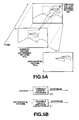
- This vector is encoded by a variable length encoder 20 shown in Fig.5B and output as a bitstream, while the difference signal thus found is encoded by a variable length encoder 21 and output as a bitstream.
- the above-mentioned block matching method is further illustrated in Fig.6 and Fig. 8.
- the portion of the frame picture PC 2 in a search range SR which has the strongest similarity in luminance pattern to that of the block under consideration BC from frame picture PC 1 is determined.
- a block in the current memory M 2 as a reference picture is denoted as A
- a block in a search memory M 1 , as a reference picture, whose candidate vector R is offset by ⁇ X, ⁇ Y is denoted as A'.
- the sum of absolute values of the differences between the values of the total pixels belonging to the block A in the current memory M 2 and the values of the pixels on the block A' in the search memory M 1 associated with the respective pixel values in the block A, for example, is calculated. This sum value is termed the residue.
- a vector ( ⁇ X, ⁇ Y) which gives a minimum residue value is selected from among the plural residues D ( ⁇ X, ⁇ Y) obtained in the search area as explained above is simply employed as an optimum motion vector.
- the average luminance of the picture on the display screen in its entirety is changed, as when the totality of pixels on the screen gradually becomes higher in luminance such that the average luminance of the picture on the display screen in its entirety becomes brighter (fade-in) or, conversely, the totality of pixels on the screen gradually becomes lower in luminance such that the average luminance of the picture on the display screen in its entirety becomes darker (fade-out), the picture portions having the strongest similarity in the luminance signal pattern are searched by the pattern matching method even though the object remains still on the screen.
- the resulting vector is significantly different from the real one.
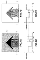
- blocks A, B and C in the picture shown in Fig.7b are detected by the block matching method as picture portions having strongest luminance signal pattern similarity to blocks A', B' and C' in Fig.7a.
- the pixel luminance on a line P'Q' of a pre-fade-in picture in Fig.7a is shown in Fig.7c, while the luminance on a line PQ of a post-fade-in picture in Fig.7b is shown in Fig.7d.
- Lines P'Q' and PQ each define a predetermined row or line of pixels on a display device.
- a luminance portion B shown in Fig.7d representing the luminance of a block B in the picture shown in Fig.7b
- a luminance portion B' of Fig.7c representing the luminance of a block B' in the picture shown in Fig.7a.
- the luminance of a block portion at the same position as the block B in the pre-fade-in picture of Fig.7a is represented by a luminance portion B'' shown in Fig.7c.
- Fig. 9 illustrates one example of an apparatus for performing the above described block matching function. It should be noted that reference numerals corresponding to like reference numerals in the illustration of the present invention shown in Fig. 1 represent like elements/components.
- the present invention provides a method and apparatus for detecting motion vector wherein a motion vector obtained by block matching wherein a luminance pattern freed of dc components from a luminance signal of a picture and thus containing only ac components is compared to a motion vector obtained by block matching wherein a luminance signal of a picture and an optimum motion vector based upon the result of comparison is adopted as a true motion vector.
- a method for comparing data representing a first sequential picture frame and a second sequential picture frame to determine a motion vector comprising the steps of:
- an apparatus for detecting a motion vector between a present frame and a preceding frame of an input digital picture signal which includes DC components and AC components comprising:
- a true motion vector is obtained using the above motion vector detecting method. Encoding and quantization are performed on a prediction picture signal afforded by the true motion vector. The resulting quantized signal and the motion vector are encoded by variable-length encoding.
- a motion vector and minimum value is selected from either a motion vector and minimum value obtained by a conventional block matching method or a motion vector and minimum value obtained by removing dc components from a luminance pattern so as to yield only ac components thereof.
- the selection between these two motion vectors and minimum values is made based upon the which of the two motion vectors has the minimum value.
- the motion vector having the minimum value is selected as an optimum motion vector obtained based upon the result of this comparison. This optimum motion vector may be employed for variable length encoding of the video signal even in cases wherein the average luminance of the picture on the screen is varied significantly.
- Fig. 1 shows a schematic of one embodiment of the present invention.
- Fig. 2A is a graph showing picture luminance distribution with the method for detecting the motion vector according to the present invention.
- Fig. 2B is a graph showing picture luminance distribution with the method for detecting the motion vector according to the present invention.
- Fig.2C is a graph showing picture luminance distribution with the method for detecting the motion vector according to the present invention.
- Fig.3A is a graph showing picture luminance distribution with the conventional method for detecting the motion vector.
- Fig.3B is a graph showing picture luminance distribution with the conventional method for detecting the motion vector.
- Fig.3C is a graph showing picture luminance distribution with the conventional method for detecting the motion vector.
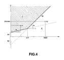
- Fig.4 is a graph showing a typical example of an evaluation function.
- Fig.5A illustrates picture signal encoding exploiting inter-frame correlation.
- Fig.5B illustrates picture signal encoding exploiting inter-frame correlation.
- Fig.6 illustrates a conventional method for detecting the motion vector.
- Fig.7a illustrates a motion vector on a picture during fade-in according to a conventional method for detecting the motion vector and the luminance distribution.
- Fig.7b illustrates a motion vector on a picture during fade-in according to a conventional method for detecting the motion vector and the luminance distribution.
- Fig.7c illustrates a motion vector on a picture during fade-in according to a conventional method for detecting the motion vector and the luminance distribution.
- Fig.7d illustrates a motion vector on a picture during fade-in according to a conventional method for detecting the motion vector and the luminance distribution.
- Fig.8 illustrates a current frame 1 and a reference frame 2 in relation to each other.
- Fig. 9 illustrates a conventional apparatus for motion vector detection.
- Fig.1 schematically shows a construction of a device for carrying out the picture signal encoding method according to the present invention.
- Data, or pixel values B, of a first frame picture, or reference picture are input via input terminal 21 to terminal 20a of input selector 20.
- Control circuit 22 controls input selector 20 to route the data (pixels value B) from input terminal 20a to either output terminal 20b or 20c.
- control circuit 22 causes input selector 20 to route the data (pixel values B) from terminal 20a to output 20c where it is then stored in frame memory 1 and routed to average luminance calulating circuit 6.
- Data, or pixel values A, of a second frame picture, or search picture is input and routed via input selector 20 to output terminal 20b where it is then stored in frame memory 2 and routed to average luminance calculating circuit 7.
- the total pixel values in a predetermined block of pixels under consideration herein represented by a value of a sole pixel A
- the pixel values in a block in a search range associated with the pixel A herein represented by a value of a sole pixel B
- the pixel values A and B read from frame memory 2 and frame memory 1, respectively, in accordance with control circuit 22, are routed to an arithmetic-logical unit 3 where an absolute value of the difference between the pixel values A and B is calculated.
- This absolute value is routed to an arithmetic-logical unit 4 where the residue D ( ⁇ X, ⁇ Y), which is the total sum of the absolute values, is calculated.
- the pixel values A and B are routed to average luminance calculating units 7 and 6, respectively.
- the average luminance calculating units 7 and 6 calculate average luminance values of the pixels A and B, respectively.
- the average value of all the A values and B values is calculated by the luminance calculating units 6 and 7.
- the average luminance values thus found are routed to an arithmetic-logical unit 8 where an absolute value of the difference between the average luminance value of the pixel A and that of the pixel B is found and routed to an arithmetic-logical unit 9.
- the arithmetic-logical unit 9 calculates a residue D AC ( ⁇ X, ⁇ Y) based on the absolute value calculated by arithmetic-logical unit 8.
- the residue is usually employed by circuitry for retrieving picture portions having strongest luminance signal pattern similarity using the block matching method.
- the block matching method is employed in such a manner as to subtract a dc component as a average luminance of a block under consideration from the pixel value in the block under consideration to give a difference, herein termed an ac component, which ac component is employed in calculating the residue.
- a motion vector may be calculated more accurately by comparing the residue D ( ⁇ X, ⁇ Y) and the residue D AC ( ⁇ X, ⁇ Y) to each other for selecting a more appropriate one of the residues.
- Fig.2a & Fig. 2b shows the luminance distribution in case the dc component has been removed from the pixel value when calculating the residue using the pictures shown in Figs.7a and 7b.
- Figs.2a and 2b show the luminance distribution in case the dc component has been removed from the pixel values on the line P'Q' in Fig.7a and that in case the dc component has been removed from the pixel values on the line PQ in Fig.7b.
- Lines PQ and P'Q' represent a selected row of pixels across a display screen 700.
- the difference between the luminance distribution in Fig.2a and that in Fig.2b is as shown shaded in Fig.2c.
- Fig.3a shows the luminance distribution of the pixel values on the line P'Q' of the picture shown in Fig.7a, as found by the conventional motion vector detecting method.
- Figs.3b and 3c show the luminance distribution of pixel values on the line PQ in Fig.7b and the difference between the luminance distribution of Fig.3a and that of Fig.3b.
- the luminance distribution shown in Figs.3a, 3b and 3c is associated with that shown in Figs.2a, 2b and 2c.
- the arithmetic-logical unit 4 of Fig.1 calculates the residue D ( ⁇ X, ⁇ Y) for the totality of blocks within the search range, while the arithmetic-logical unit 9 of Fig.1 calculates the residue D AC ( ⁇ X, ⁇ Y) for the totality of blocks within the search range.
- the residue D AC ( ⁇ X, ⁇ Y) as found by the arithmetic-logical unit 4 and the residue D AC ( ⁇ X, ⁇ Y) as found by the arithmetic-logical unit 9 are routed to minimum value calculating units 5, 10, respectively.
- the minimum value of the residue D ( ⁇ X, ⁇ Y) and the minimum value of the residue D AC ( ⁇ X, ⁇ Y) are selected by the minimum value calculating units 5, 10, respectively.
- the minimum value of the residue D ( ⁇ X, ⁇ Y) and the minimum value of the residue D AC ( ⁇ X, ⁇ Y), selected by the minimum value calculating units 5, 10, respectively, are routed to an evaluating unit 11 where the two minimum values of the residues are compared to each other in accordance with a pre-set evaluation standard. The resulting value of comparison is fed to signal switching units 12 and 13.
- the signal switching unit 12 is configured to effect switching between the minimum values of the residues as found by the above-described two motion vector detecting methods.
- the signal switching unit 12 has its input terminals a and b supplied with the minimum value of the residue D AC ( ⁇ X, ⁇ Y) from the minimum value calculating unit 10 and with the minimum value of the residue D ( ⁇ X, ⁇ Y) from the minimum value calculating unit 5, respectively.
- the signal switching unit 13 is configured to effect switching between the motion vectors obtained by the above-described two motion vector detecting methods.
- the signal switching unit 13 has its input terminals c and d with the motion vector from the minimum value calculating unit 10 and with the motion vector from the minimum value calculating unit 5, respectively.
- These signal switching units 12, 13 are changed over responsive to the results output from the evaluating unit 11 so that the minimum value of the residue and the motion vector as found by one of the two motion vector detection methods are routed to a motion picture encoder 14.
- the minimum value of the residue and the motion vector from the minimum value calculating unit 10 are routed via the signal switching units 12 and 13 to the motion picture encoder 14.
- the minimum value of the residue and the motion vector from the minimum value calculating unit 10 are routed via the signal switching units 12 and 13 to the motion picture encoder 14.
- the motion picture encoder 14 effectuates the encoding using predicted picture signals and processes the encoded signal in a pre-set manner.
- the motion picture encoder 14 also quantizes the processed signal and variable-length encodes the quantized signal and the motion vector.
- the evaluating unit 11 sets, or determines, an evaluation function based upon plural types of sequences and the function thus set is followed without simply selecting a smaller one of the evaluation functions. In other words, evaluating unit 11 outputs a signal based upon which of the minimum values signals D min or D acmin , from minimum value calculating units 5 and 10, respectively, meet the predetermined criteria.
- Fig.4 shows illustrative examples of the evaluation function(criteria).
- a pre-set value of the residue D ( ⁇ X, ⁇ Y) is e n1 which is defined by and corresponds to the point of intersection of lines S1 and S2 as shown in Fig. 4.
- the minimum value D ACmin of the residue D AC ( ⁇ X, ⁇ Y) is such that D acmin. > ⁇ 1 (D min. ) + ⁇ 1
- the minimum value D min. of the residue D( ⁇ X, ⁇ Y) is such that D acmin ⁇ ⁇ 2 (D min. ) D min. + ⁇ 1 , for 0 ⁇ ⁇ e n1 .
- the minimum value D acmin of the residue D AC ( ⁇ X, ⁇ Y) is such that D acmin > ⁇ 2 (D min ) + ⁇ 2
- the minimum value D min. of the residue D( ⁇ X, ⁇ Y) is such that D acmin. ⁇ ⁇ 2 (D min. ) + ⁇ 2 , for e n1 ⁇ ⁇ 2 .
- the evaluation unit 11 causes the switches 12 and 13 to output the signals from terminals B and D to motion picture encoder 14.
- the evaluation unit 11 causes the switches 12 and 13 to output the signals from terminals A and C to motion picture encoder 14.
- Motion picture encoder 14 may be, for example, a MPEG or MPEG II type motion picture encoding device.
Landscapes
- Engineering & Computer Science (AREA)
- Multimedia (AREA)
- Signal Processing (AREA)
- Compression Or Coding Systems Of Tv Signals (AREA)
Claims (8)
- Procédé destiné à comparer des données représentant une première trame d'image séquentielle et une seconde trame d'image séquentielle destinée à déterminer un vecteur de mouvement, comprenant les étapes consistant à :générer un premier vecteur de mouvement en mettant en correspondance les blocs desdites données de ladite première trame d'image séquentielle et de ladite seconde trame d'image séquentielle, dans lequel les composantes continues ont été éliminées du signal de luminance des deux trames d'image séquentielles afin de comprendre uniquement les composantes alternatives ;générer un second vecteur de mouvement en mettant en correspondance les blocs desdites données de ladite première trame d'image séquentielle et de ladite seconde trame d'image séquentielle, dans lequel la différence entre lesdites premières données de trame d'image séquentielle et lesdites secondes données de trame d'image séquentielle est calculée ;comparer ledit premier vecteur de mouvement et ledit second vecteur de mouvement destiné à déterminer un vecteur de mouvement optimal ; etsortir soit ledit premier vecteur de mouvement, soit ledit second vecteur de mouvement en tant que vecteur de mouvement optimal en fonction de ladite comparaison.
- Procédé destiné à coder un signal d'image, comprenant les étapes consistant à :générer un vecteur de mouvement optimal selon le procédé de la revendication 1 ;effectuer un codage et une quantification sur un signal d'image de prédiction généré en utilisant ledit vecteur de mouvement optimal ; eteffectuer un codage de longueur variable sur le signal quantifié résultant et sur le vecteur de mouvement.
- Procédé selon la revendication 1 ou 2, dans lequel : l'étape de génération d'un premier vecteur de mouvement comprend la génération d'une première valeur minimale ; l'étape de génération d'un second vecteur de mouvement comprend la génération d'une seconde valeur minimale ; et l'étape de comparaison détermine le vecteur de mouvement optimal sur la base de ladite première valeur minimale et de ladite seconde valeur minimale.
- Dispositif destiné à détecter un vecteur de mouvement entre une trame actuelle et une trame précédente d'un signal d'image numérique d'entrée qui comprend des composantes continues et des composantes alternatives, comprenant :des moyens d'élimination (8) destinés à éliminer les composantes continues du signal d'image numérique d'entrée de manière à fournir un signal d'image numérique contenant uniquement des composantes alternatives ;des premiers moyens de génération de vecteur de mouvement (8, 9, 10) destinés à générer un premier vecteur de mouvement et une première valeur minimale à partir du signal d'image numérique fourni par lesdits moyens d'élimination en utilisant un algorithme de correspondance de blocs ;des seconds moyens de génération de vecteur de mouvement (3, 4, 5) destinés à générer un second vecteur de mouvement et une seconde valeur minimale à partir du signal d'image numérique d'entrée en utilisant un algorithme de correspondance de blocs ;des moyens d'évaluation (11) destinés à évaluer, sur la base desdites première et seconde valeurs minimales, lesdits premier et second vecteurs de mouvement destinés à déterminer lequel correspond à des critères prédéterminés ; etdes moyens de sélection (12, 13) destinés à sortir de manière sélective ledit premier vecteur de mouvement ou ledit second vecteur de mouvement en fonction de ladite détermination desdits moyens d'évaluation.
- Dispositif selon la revendication 4, dans lequel lesdits premiers moyens de génération de vecteur de mouvement comprennent, de plus, des moyens de calcul (9) destinés à calculer une valeur d'intégration des valeurs absolues de différences des valeurs de luminance à chaque position associée entre un bloc de référence dans une trame précédente et un bloc examiné dans la trame actuelle.
- Dispositif selon la revendication 5, comprenant, de plus, des premiers moyens (10) destinés à détecter la valeur d'intégration la plus petite et à générer le premier vecteur de mouvement en fonction d'une position du bloc de référence ayant la valeur d'intégration la plus petite, dans lequel :lesdits seconds moyens de génération de vecteur de mouvement comprennent des moyens de calcul (4) destinés à calculer une valeur d'intégration des valeurs absolues de différences de la valeur de luminance à chaque position associée entre un bloc de référence dans une trame précédente et un bloc examiné dans la trame actuelle et des seconds moyens (5) destinés à détecter la valeur d'intégration la plus petite et à générer le second vecteur de mouvement conformément à la valeur d'intégration la plus petite ; etlesdits moyens d'évaluation (11) évaluent lequel dudit premier ou second vecteur de mouvement est préférable en se basant sur les valeurs d'intégration les plus petites fournies par lesdits premiers moyens de détection et par lesdits seconds moyens de détection.
- Dispositif selon l'une quelconque des revendications 4 à 6, dans lequel :lesdits premiers moyens de génération de vecteur de mouvement comprennent une première unité arithmétique et logique destinée à calculer un premier signal de différence entre les valeurs de luminance de ladite trame actuelle et lesdites données de trame précédente selon l'expression :dans lequel ledit premier vecteur de mouvement et la première valeur minimale sont calculés conformément à ladite sortie de ladite première unité arithmétique et logique ;lesdits moyens d'élimination comprennent la première unité de calcul de luminance moyenne destinée à calculer la valeur de luminance moyenne desdites données de trame précédente et la seconde unité de calcul de luminance moyenne destinée à calculer la valeur de luminance moyenne desdites données de trame actuelle ;lesdits seconds moyens de génération de vecteur de mouvement comprennent une seconde unité arithmétique et logique destinée à générer un second signal de différence selon l'expression :lesdits élément de circuit d'évaluation comparent la valeur dudit premier signal de différence avec la valeur dudit second signal de différence pour déterminer quelle valeur correspond à des critères prédéterminés.
- Dispositif destiné à coder un signal vidéo, comprenant un dispositif selon la revendication 7 et des éléments de circuit de codeur pour coder ledit signal vidéo conformément audit vecteur de mouvement optimal et à ladite valeur.
Applications Claiming Priority (3)
| Application Number | Priority Date | Filing Date | Title |
|---|---|---|---|
| JP175529/94 | 1994-07-27 | ||
| JP17552994 | 1994-07-27 | ||
| JP17552994 | 1994-07-27 |
Publications (2)
| Publication Number | Publication Date |
|---|---|
| EP0695096A1 EP0695096A1 (fr) | 1996-01-31 |
| EP0695096B1 true EP0695096B1 (fr) | 2000-03-22 |
Family
ID=15997665
Family Applications (1)
| Application Number | Title | Priority Date | Filing Date |
|---|---|---|---|
| EP95305243A Expired - Lifetime EP0695096B1 (fr) | 1994-07-27 | 1995-07-27 | Dispositif pour détecter des vecteurs de mouvement |
Country Status (4)
| Country | Link |
|---|---|
| US (1) | US5691774A (fr) |
| EP (1) | EP0695096B1 (fr) |
| KR (1) | KR100349883B1 (fr) |
| DE (1) | DE69515755T2 (fr) |
Families Citing this family (10)
| Publication number | Priority date | Publication date | Assignee | Title |
|---|---|---|---|---|
| US6320906B1 (en) * | 1996-05-21 | 2001-11-20 | Matsushita Electric Industrial Co., Ltd. | Motion vector detecting circuit |
| JP2002513515A (ja) | 1996-06-10 | 2002-05-08 | モーフィックス テクノロジー インコーポレイテッド | 情報通信用の方法及び装置 |
| DE19703251A1 (de) * | 1997-01-29 | 1998-11-05 | Kuhn Peter Dipl Ing | Eine flexible VLSI Architektur für Blockmatching mit variabler Blockgröße, für Teilblockkombinationen, beliebig berandete Objekte und Luminanzkorrektur |
| US6696992B1 (en) * | 2001-10-02 | 2004-02-24 | Allan Chu | Efficient data encoding and decoding processes |
| EP1827029A1 (fr) * | 2002-01-18 | 2007-08-29 | Kabushiki Kaisha Toshiba | Procédé et appareil de décodage vidéo |
| DE10236859A1 (de) * | 2002-08-07 | 2004-02-19 | Takata Corp. | Gassack für ein Airbagmodul |
| US8644379B2 (en) * | 2007-03-07 | 2014-02-04 | Himax Technologies Limited | De-interlacing method and method of compensating a de-interlaced pixel |
| KR101668829B1 (ko) * | 2010-04-21 | 2016-10-25 | 삼성전자주식회사 | 공간 주파수 상에서 인간 시각 특성이 반영된 텍스처 향상 방법 및 장치 |
| CN104125477B (zh) * | 2013-04-27 | 2017-08-18 | 华为技术有限公司 | 一种视频帧淡入/淡出检测方法及装置 |
| EP4242608A3 (fr) * | 2016-09-02 | 2023-12-06 | X-Rite Europe GmbH | Appareil et procédé d'identification de pigment à effet |
Citations (1)
| Publication number | Priority date | Publication date | Assignee | Title |
|---|---|---|---|---|
| WO1993017525A1 (fr) * | 1992-02-26 | 1993-09-02 | British Broadcasting Corporation | Traitement d'image video a compensation de mouvement |
Family Cites Families (11)
| Publication number | Priority date | Publication date | Assignee | Title |
|---|---|---|---|---|
| US4371895A (en) * | 1980-01-18 | 1983-02-01 | Nippon Electric Co., Ltd. | Coded video signal transmitting and receiving system |
| JPS61113377A (ja) * | 1984-11-07 | 1986-05-31 | Sony Corp | テレビジヨン信号の動き検出装置 |
| US4951140A (en) * | 1988-02-22 | 1990-08-21 | Kabushiki Kaisha Toshiba | Image encoding apparatus |
| US4897720A (en) * | 1988-03-14 | 1990-01-30 | Bell Communications Research, Inc. | Circuit implementation of block matching algorithm |
| GB8909498D0 (en) * | 1989-04-26 | 1989-06-14 | British Telecomm | Motion estimator |
| GB2248361B (en) * | 1990-09-28 | 1994-06-01 | Sony Broadcast & Communication | Motion dependent video signal processing |
| JPH04177992A (ja) * | 1990-11-09 | 1992-06-25 | Victor Co Of Japan Ltd | 階層性を有する画像符号化装置 |
| JPH04207788A (ja) * | 1990-11-30 | 1992-07-29 | Sony Corp | 画像信号符号化装置及び方法 |
| JP3103894B2 (ja) * | 1991-02-06 | 2000-10-30 | ソニー株式会社 | ビデオデータの手振れ補正装置およびその方法 |
| JP3263960B2 (ja) * | 1991-10-22 | 2002-03-11 | ソニー株式会社 | 動きベクトル符号器および復号器 |
| JP3230263B2 (ja) * | 1992-01-31 | 2001-11-19 | ソニー株式会社 | 動きベクトル検出回路 |
-
1995
- 1995-07-25 KR KR1019950022169A patent/KR100349883B1/ko not_active Expired - Fee Related
- 1995-07-26 US US08/507,103 patent/US5691774A/en not_active Expired - Lifetime
- 1995-07-27 DE DE69515755T patent/DE69515755T2/de not_active Expired - Fee Related
- 1995-07-27 EP EP95305243A patent/EP0695096B1/fr not_active Expired - Lifetime
Patent Citations (1)
| Publication number | Priority date | Publication date | Assignee | Title |
|---|---|---|---|---|
| WO1993017525A1 (fr) * | 1992-02-26 | 1993-09-02 | British Broadcasting Corporation | Traitement d'image video a compensation de mouvement |
Also Published As
| Publication number | Publication date |
|---|---|
| DE69515755T2 (de) | 2000-07-13 |
| US5691774A (en) | 1997-11-25 |
| KR960006646A (ko) | 1996-02-23 |
| DE69515755D1 (de) | 2000-04-27 |
| EP0695096A1 (fr) | 1996-01-31 |
| KR100349883B1 (ko) | 2002-12-16 |
Similar Documents
| Publication | Publication Date | Title |
|---|---|---|
| US4951140A (en) | Image encoding apparatus | |
| KR0168458B1 (ko) | 움직임 보상을 갖는 프레임간 혼성 부호기에서의 왜곡을 감소시키는 장치 및 방법 그리고 그에 대한 부호화 시스템 | |
| US6163574A (en) | Motion picture encoding system for either intra-frame encoding or inter-frame encoding | |
| US6542642B2 (en) | Image coding process and motion detecting process using bidirectional prediction | |
| US6414992B1 (en) | Optimal encoding of motion compensated video | |
| USRE37091E1 (en) | Motion compensated prediction interframe coding system | |
| US6037986A (en) | Video preprocessing method and apparatus with selective filtering based on motion detection | |
| US7590180B2 (en) | Device for and method of estimating motion in video encoder | |
| US6226327B1 (en) | Video coding method and apparatus which select between frame-based and field-based predictive modes | |
| EP0833503A2 (fr) | Détecteur de changement de scène pour vidéo numérique | |
| US5592302A (en) | Coding method for coding pixel blocks and apparatus therefor | |
| US5589884A (en) | Adaptive quantization controlled by scene change detection | |
| EP0512854B1 (fr) | Codage des signaux vidéo | |
| US20150312586A1 (en) | Image decoding device and method thereof using inter-coded predictive encoding code | |
| EP0597647A2 (fr) | Codage de signaux vidéo | |
| KR20030024781A (ko) | 비디오 신호에서의 자막 검출 | |
| WO1996036182A1 (fr) | Codeur mpeg determinant de maniere concurrente le format et le controle de la cadence de codage de donnees video | |
| US5387938A (en) | Adaptive interframe/intraframe block coding method and apparatus | |
| US5691774A (en) | Apparatus for detecting motion vector and encoding picture signals | |
| JPH07112284B2 (ja) | 予測符号化装置及び復号化装置 | |
| US5691775A (en) | Reduction of motion estimation artifacts | |
| US5689312A (en) | Block matching motion estimation method | |
| US20070092007A1 (en) | Methods and systems for video data processing employing frame/field region predictions in motion estimation | |
| KR0181029B1 (ko) | 에지를 이용한 특징점 선정장치 | |
| EP0520789A2 (fr) | Codeur vidéo et méthode de codage |
Legal Events
| Date | Code | Title | Description |
|---|---|---|---|
| PUAI | Public reference made under article 153(3) epc to a published international application that has entered the european phase |
Free format text: ORIGINAL CODE: 0009012 |
|
| AK | Designated contracting states |
Kind code of ref document: A1 Designated state(s): DE FR GB NL |
|
| 17P | Request for examination filed |
Effective date: 19960705 |
|
| 17Q | First examination report despatched |
Effective date: 19980901 |
|
| GRAG | Despatch of communication of intention to grant |
Free format text: ORIGINAL CODE: EPIDOS AGRA |
|
| RTI1 | Title (correction) |
Free format text: APPARATUS FOR DETECTING MOTION VECTOR |
|
| GRAG | Despatch of communication of intention to grant |
Free format text: ORIGINAL CODE: EPIDOS AGRA |
|
| GRAH | Despatch of communication of intention to grant a patent |
Free format text: ORIGINAL CODE: EPIDOS IGRA |
|
| GRAH | Despatch of communication of intention to grant a patent |
Free format text: ORIGINAL CODE: EPIDOS IGRA |
|
| GRAA | (expected) grant |
Free format text: ORIGINAL CODE: 0009210 |
|
| AK | Designated contracting states |
Kind code of ref document: B1 Designated state(s): DE FR GB NL |
|
| REF | Corresponds to: |
Ref document number: 69515755 Country of ref document: DE Date of ref document: 20000427 |
|
| ET | Fr: translation filed | ||
| PLBE | No opposition filed within time limit |
Free format text: ORIGINAL CODE: 0009261 |
|
| STAA | Information on the status of an ep patent application or granted ep patent |
Free format text: STATUS: NO OPPOSITION FILED WITHIN TIME LIMIT |
|
| 26N | No opposition filed | ||
| REG | Reference to a national code |
Ref country code: GB Ref legal event code: IF02 |
|
| PGFP | Annual fee paid to national office [announced via postgrant information from national office to epo] |
Ref country code: DE Payment date: 20080807 Year of fee payment: 14 |
|
| PGFP | Annual fee paid to national office [announced via postgrant information from national office to epo] |
Ref country code: NL Payment date: 20080703 Year of fee payment: 14 Ref country code: FR Payment date: 20080718 Year of fee payment: 14 |
|
| PGFP | Annual fee paid to national office [announced via postgrant information from national office to epo] |
Ref country code: GB Payment date: 20080806 Year of fee payment: 14 |
|
| GBPC | Gb: european patent ceased through non-payment of renewal fee |
Effective date: 20090727 |
|
| NLV4 | Nl: lapsed or anulled due to non-payment of the annual fee |
Effective date: 20100201 |
|
| REG | Reference to a national code |
Ref country code: FR Ref legal event code: ST Effective date: 20100331 |
|
| PG25 | Lapsed in a contracting state [announced via postgrant information from national office to epo] |
Ref country code: FR Free format text: LAPSE BECAUSE OF NON-PAYMENT OF DUE FEES Effective date: 20090731 |
|
| PG25 | Lapsed in a contracting state [announced via postgrant information from national office to epo] |
Ref country code: GB Free format text: LAPSE BECAUSE OF NON-PAYMENT OF DUE FEES Effective date: 20090727 |
|
| PG25 | Lapsed in a contracting state [announced via postgrant information from national office to epo] |
Ref country code: DE Free format text: LAPSE BECAUSE OF NON-PAYMENT OF DUE FEES Effective date: 20100202 |
|
| PG25 | Lapsed in a contracting state [announced via postgrant information from national office to epo] |
Ref country code: NL Free format text: LAPSE BECAUSE OF NON-PAYMENT OF DUE FEES Effective date: 20100201 |