EP0695260B1 - Process and plant for packaging fluid or semi-fluid products in thermoformable synthetic resin containers - Google Patents
Process and plant for packaging fluid or semi-fluid products in thermoformable synthetic resin containers Download PDFInfo
- Publication number
- EP0695260B1 EP0695260B1 EP94906352A EP94906352A EP0695260B1 EP 0695260 B1 EP0695260 B1 EP 0695260B1 EP 94906352 A EP94906352 A EP 94906352A EP 94906352 A EP94906352 A EP 94906352A EP 0695260 B1 EP0695260 B1 EP 0695260B1
- Authority
- EP
- European Patent Office
- Prior art keywords
- die
- web
- chamber
- tubular means
- container
- Prior art date
- Legal status (The legal status is an assumption and is not a legal conclusion. Google has not performed a legal analysis and makes no representation as to the accuracy of the status listed.)
- Expired - Lifetime
Links
- 239000012530 fluid Substances 0.000 title claims abstract description 11
- 229920003002 synthetic resin Polymers 0.000 title claims abstract description 6
- 239000000057 synthetic resin Substances 0.000 title claims abstract description 6
- 238000000034 method Methods 0.000 title claims description 18
- 238000004806 packaging method and process Methods 0.000 title claims description 5
- 238000003825 pressing Methods 0.000 claims abstract description 6
- 238000007789 sealing Methods 0.000 claims description 7
- 238000010438 heat treatment Methods 0.000 claims description 5
- 238000000926 separation method Methods 0.000 claims description 4
- 230000000295 complement effect Effects 0.000 claims description 2
- 238000002347 injection Methods 0.000 claims description 2
- 239000007924 injection Substances 0.000 claims description 2
- 238000005476 soldering Methods 0.000 abstract description 18
- 241000761557 Lamina Species 0.000 description 5
- 239000007788 liquid Substances 0.000 description 3
- 230000001954 sterilising effect Effects 0.000 description 3
- 238000005520 cutting process Methods 0.000 description 2
- 239000000463 material Substances 0.000 description 2
- 229920005989 resin Polymers 0.000 description 2
- 239000011347 resin Substances 0.000 description 2
- 229910000679 solder Inorganic materials 0.000 description 2
- 230000004913 activation Effects 0.000 description 1
- 230000002706 hydrostatic effect Effects 0.000 description 1
- 238000005304 joining Methods 0.000 description 1
- 238000004519 manufacturing process Methods 0.000 description 1
- 235000011837 pasties Nutrition 0.000 description 1
- 230000001681 protective effect Effects 0.000 description 1
- 238000004659 sterilization and disinfection Methods 0.000 description 1
- 238000003856 thermoforming Methods 0.000 description 1
- 238000011144 upstream manufacturing Methods 0.000 description 1
Images


Classifications
-
- B—PERFORMING OPERATIONS; TRANSPORTING
- B29—WORKING OF PLASTICS; WORKING OF SUBSTANCES IN A PLASTIC STATE IN GENERAL
- B29C—SHAPING OR JOINING OF PLASTICS; SHAPING OF MATERIAL IN A PLASTIC STATE, NOT OTHERWISE PROVIDED FOR; AFTER-TREATMENT OF THE SHAPED PRODUCTS, e.g. REPAIRING
- B29C49/00—Blow-moulding, i.e. blowing a preform or parison to a desired shape within a mould; Apparatus therefor
- B29C49/02—Combined blow-moulding and manufacture of the preform or the parison
- B29C49/06905—Using combined techniques for making the preform
- B29C49/0691—Using combined techniques for making the preform using sheet like material, e.g. sheet blow-moulding from joined sheets
-
- B—PERFORMING OPERATIONS; TRANSPORTING
- B65—CONVEYING; PACKING; STORING; HANDLING THIN OR FILAMENTARY MATERIAL
- B65B—MACHINES, APPARATUS OR DEVICES FOR, OR METHODS OF, PACKAGING ARTICLES OR MATERIALS; UNPACKING
- B65B3/00—Packaging plastic material, semiliquids, liquids or mixed solids and liquids, in individual containers or receptacles, e.g. bags, sacks, boxes, cartons, cans, or jars
- B65B3/02—Machines characterised by the incorporation of means for making the containers or receptacles
- B65B3/022—Making containers by moulding of a thermoplastic material
-
- B—PERFORMING OPERATIONS; TRANSPORTING
- B29—WORKING OF PLASTICS; WORKING OF SUBSTANCES IN A PLASTIC STATE IN GENERAL
- B29C—SHAPING OR JOINING OF PLASTICS; SHAPING OF MATERIAL IN A PLASTIC STATE, NOT OTHERWISE PROVIDED FOR; AFTER-TREATMENT OF THE SHAPED PRODUCTS, e.g. REPAIRING
- B29C49/00—Blow-moulding, i.e. blowing a preform or parison to a desired shape within a mould; Apparatus therefor
- B29C49/42—Component parts, details or accessories; Auxiliary operations
- B29C49/46—Component parts, details or accessories; Auxiliary operations characterised by using particular environment or blow fluids other than air
- B29C2049/4602—Blowing fluids
- B29C2049/4635—Blowing fluids being sterile
-
- B—PERFORMING OPERATIONS; TRANSPORTING
- B29—WORKING OF PLASTICS; WORKING OF SUBSTANCES IN A PLASTIC STATE IN GENERAL
- B29C—SHAPING OR JOINING OF PLASTICS; SHAPING OF MATERIAL IN A PLASTIC STATE, NOT OTHERWISE PROVIDED FOR; AFTER-TREATMENT OF THE SHAPED PRODUCTS, e.g. REPAIRING
- B29C49/00—Blow-moulding, i.e. blowing a preform or parison to a desired shape within a mould; Apparatus therefor
- B29C49/42—Component parts, details or accessories; Auxiliary operations
- B29C49/46—Component parts, details or accessories; Auxiliary operations characterised by using particular environment or blow fluids other than air
- B29C2049/4673—Environments
- B29C2049/4697—Clean room
-
- B—PERFORMING OPERATIONS; TRANSPORTING
- B29—WORKING OF PLASTICS; WORKING OF SUBSTANCES IN A PLASTIC STATE IN GENERAL
- B29C—SHAPING OR JOINING OF PLASTICS; SHAPING OF MATERIAL IN A PLASTIC STATE, NOT OTHERWISE PROVIDED FOR; AFTER-TREATMENT OF THE SHAPED PRODUCTS, e.g. REPAIRING
- B29C49/00—Blow-moulding, i.e. blowing a preform or parison to a desired shape within a mould; Apparatus therefor
- B29C49/02—Combined blow-moulding and manufacture of the preform or the parison
- B29C49/06905—Using combined techniques for making the preform
- B29C49/0691—Using combined techniques for making the preform using sheet like material, e.g. sheet blow-moulding from joined sheets
- B29C49/06916—Means for avoiding parts of the sheets to stick together, e.g. to provide blow opening
-
- B—PERFORMING OPERATIONS; TRANSPORTING
- B29—WORKING OF PLASTICS; WORKING OF SUBSTANCES IN A PLASTIC STATE IN GENERAL
- B29C—SHAPING OR JOINING OF PLASTICS; SHAPING OF MATERIAL IN A PLASTIC STATE, NOT OTHERWISE PROVIDED FOR; AFTER-TREATMENT OF THE SHAPED PRODUCTS, e.g. REPAIRING
- B29C65/00—Joining or sealing of preformed parts, e.g. welding of plastics materials; Apparatus therefor
Definitions
- the invention concerns a process and an apparatus according to the preambles of claims 1 and 9 respectively for the packaging of fluid or semi-fluid products (that is, in liquid, semi-liquid, pasty, powdery form or in small-sized pieces) in thermoformable synthetic resin containers.
- Prior art involves a process in which the chamber of the container is formed by first placing in a die two laminas of thermoformable synthetic resin in such a way that the opposing faces of the die, which surround the cavity of the die, heat solder the two laminas so as to create an unexpanded envelope within the cavity of the die. Immediately afterwards, a hot pressurized gas is introduced into the unexpanded envelope through one or more thin conduits to expand it, pressing its sides against the internal surfaces of the die that define the external shape of the container. Subsequently the said conduits are retracted and the laminas are completely soldered, also in the areas through which the said conduits passed. Subsequently the chamber is cut in a suitable area in order to create an opening; it is then filled through the said opening and finally the opening is re-closed by soldering in order to seal the contents.
- US-A-3 423 902 discloses a process and an apparatus according to the preamble of claim 1 and claim 9 respectively for the manufacture of flanged plastic containers in which two vertical curtains of thermoformable plastic material are inserted in the cavity of a die, a vertical tubular element being interposed between them, said tubular element being provided with a plurality of longitudinal passages through which selectively pressurized air is injected to form the container and subsequently a filling product is introduced into the container itself.
- the container manufactured by means of said plant cannot be completely filled with the product because at least the presence of the tubular element in the container as filling of the product into the container is completed prevents complete filling of the container before sealing the formed container.
- a first object of the invention is to find a process which is generally more economical and rational, is quicker and permits the container to be completely filled (leaving no air).
- a further object of the invention is to find a process which is more suited to the packaging of products in a sterile manner, preventing contact of the chamber with the surrounding air and also preventing shards of material, produced when the container is cut in order to create an opening, from falling into the chamber itself: this being a drawback of some of the prior art.
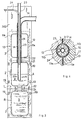
- Fig. 1 is a general schematic representation of a first embodiment of the plant.
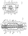
- Fig. 2 is an enlarged detail of Fig. 1.
- Fig. 3 is section III-III of Fig. 2.
- Fig. 4 is section IV-IV of Fig. 2
- Fig. 5 is the axial section of Fig. 2
- Fig. 6 is a schematic representation of a second embodiment of the plant.
- Fig. 7 is a schematic representation of forming station 10 ink a further embodiment.
- the plant includes a forming station 10 with a die 11 including two complementary hollow sections 11b, or halves, whose cavity 12 defines the shape of chamber 2 of the container.
- the hollow sections 11b respectively, have matching faces 11a that close cavity 12, and which are preferably arranged in an essentially vertical separation plane.
- a tubular element 14 passes through at least the upper part of cavity 12 preferably with an essentially vertical axis and placed in the separation plane between sections 11b. In the embodiments illustrated in the figures, the tubular element 14 crosses cavity 12 and extends beyond it both above and below it.
- Upstream of the die 11 feeding means are provided to supply a continuous lamina of heat solderable resin in such a way as to cover the tubular element 14 and to form around it an unexpanded envelope 2a within cavity 12 (Fig. 3).
- the embodiment illustrated in Figures 1 to 5 comprises feeding means, particularly two spools 31 from which, respectively, two continuous sheets 32 of heat solderable resin lamina 3 are unrolled, said sheets passing through sterilization means 60 and heating means 65; subsequently said sheets, parallel and in contact with each other, pass between the hollow sections 11b of the die, with tubular element 14 between them.
- Each hollow section 11b is provided with two symmetrically distributed recesses 13 (Fig. 4), having a preferably semi-cylindrical shape, one above and one below, defining two cylindrical through-holes allowing the tubular element 14 to pass through the sides of die 11.
- the recesses 13 matching together when the hollow sections fit around tubular element 14.
- the die 11 presses the two sheets 32 together by means of its faces 11a and solders said sheets in the respective areas of contact by means of heat produced by suitable heating elements, such as electric resistances.
- the recesses 13 also press the sheets 3 against those parts of the tubular element 14 that pass through the sides of die 11.
- the two sheets 32 inside the cavity 12 make up the unexpanded envelope 2a, which is hermetically sealed by the joining of the two faces 11a and by the recesses 13 fitting around the tubular element 14.
- the forming station 10 is also provided with forming means to introduce pressurized fluid, in particular sterile air, into the envelope 2a when it is closed by the die 11 and the tubular element 14, that causes it to expand until its sides adhere to the walls of the cavity 12, thereby obtaining the final shape of the chamber 2.
- pressurized fluid in particular sterile air
- Said forming means can preferably be defined by the tubular element 14 itself, communicating, above, with means (not shown) that supply the pressurized air, and inside with the cavity 12 by means of openings 15.
- the die 11 With each forming cycle of the chambers 2, the die 11 is closed around the sheets 32 in contact with each other and which enclose the tubular element 14; thus, edges 32a of sheets 32 around cavity 12 are soldered, whereas they are not soldered in the areas that are in contact with the element 14, though they are kept pressed against it thereby keeping the envelope 2a closed; the pressurized air is then introduced into the envelope 2a through the tubular element 14 and the envelope 2a expands and becomes permanently shaped by cavity 12.
- the resulting chamber has an upper hole 21 and a lower hole 22, preferably of the same diameter, due to the presence of the tubular element 14 at the points where it passes through the sides of the die.
- the die 11 is opened and, by means of appropriate driving means (such as motorized rollers 19), the laminas 3, together with the chamber 2, are advanced downwards a distance equal to the vertical length of the die 11, or a little less.
- driving means such as motorized rollers 19
- the laminas 3, together with the chamber 2 are advanced downwards a distance equal to the vertical length of the die 11, or a little less.
- a continuous strip is created in the laminas 3, advancing downwards, that consists of a plurality of chambers 2 communicating with each other by means of contiguous openings 21 and 22 in the lower part of each chamber 2 and in the upper part of the next chamber 2 below it.
- the plant Beneath the forming station 10 the plant includes a soldering station 40.
- the chambers 2, as soon as they have been formed, are moved on with intermittent motion, alternately with the forming cycle (or even with a continuous motion), arriving first at an intermediate position A, beneath the die 11, and subsequently on to the soldering station 40, where by means of soldering means 41, an upper opening 21 of the chamber 2 that is positioned in the soldering station 40 and a lower opening 22 of the chamber 2 above it are closed by soldering.
- the product 9 to be packaged is introduced in the succession of chambers 2 through the tubular element 14 whose lower outlet is in the intermediate position A.
- the product 9 is preferably supplied through a filling conduit 23 that passes through the entire length of the tubular element 14 and which communicates above with filling means (of conventional type and not shown) that supply the product, whilst at the bottom end, the outlet is beneath the die 11.
- Said supply can be continuous or intermittent.
- a breather conduit 24, or vent is provided to enable the air to be expelled during the introduction of product 9.
- a collar 16 (Fig. 4) is provided to stiffen the tubular element 14 against the pressure of the die 11.
- An upper collar 16 positioned in an upper part (Fig. 4) of the die 11 is crossed by conduits 23 and 24 and by holes 17 that enable the passage of pressurized air; a lower collar 16 at a lower part of the die is crossed only by conduits 23 and 24 and blocks the passage of the pressurized air since the latter must only be introduced in the cavity 12.
- the supply of the product 9 is such that when the chamber 2 is in the soldering station 40 and before its upper opening 21 is soldered the level of the product 9 is above the opening 21 (as illustrated in Fig. 5). At this point the soldering means 41 close both opening 21 and the opening 22 of chamber 2 above it.
- soldering cycles it is advantageous for the soldering cycles to occur at the same time as the forming cycles while the strip of chambers 2 is stationary.
- a number of chambers 2 may be provided so as to form a larger volume to be filled with the product 9.
- the product when sealing of the container takes place in the soldering station 40 by activation of the soldering means 41, the product may partially fill the chamber 2 in the intermediate position A, thereby preventing the presence of air in the sealed container, the latter having been constantly kept under an hydrostatic head determined by the excees of product.
- each chamber 2 from the strip can take place in the soldering station 40 after it has been filled and closed with soldering means 41. This can occur by cutting the strip along a line T in a median position along the soldering area so as to leave both upper opening 21 of the chamber 2 containing the product 9 and lower opening 22 of chamber 2 above it closed. At the same time as cut T, cutting means 42 can carry out a contouring cut along line R in order to separate part of the soldered edge from chamber 2 to give the container the desired shape.
- the final container obtained can be of any known type that can be obtained by means of injection of heated gas with resulting thermoforming.
- the cut along line T is made, it is possible to incorporate a line of weakness close to the upper opening 21 that enables it to be opened by the user.
- the shape of the container may be different from the shape shown in the drawings: for instance the container may be provided with a supplementary opening distinct from the opening 21 that enables it to be opened by the user.
- the two sheets 32 can be unwound from two separate spools 31 (as illustrated in Fig. 1) or from a single spool on which the sheet has already been folded longitudinally. According to an alternative embodiment, the sheet can be folded after it has been unwound from the spool so as to have two sheets side by side in contact with each other.
- the longitudinal fold line of sheets 32 can pass through cavity 12 without being pressed between faces 11a of the die.
- a single spool 33 from which a single sheet 34 is unwound by means of known guiding devices (not shown); it is folded so as to wrap around tubular element 14 with the edges of sheet 34 overlapping each other in a longitudinal direction; said edges are then soldered together, for example, by heating them with hot air supplied through a tube 36 and pressing them together against tubular element 14 using roller 37.
- a continuous cylindrical sheath is obtained wrapped closely around the tubular element 14 which is led through die 11 where it forms the unexpanded envelope 2a; said cylindrical sheath is then closed by the contact with recesses 13 that press it against the external surface of the tubular element 14.
- the subsequent forming of chambers 2 using pressurized hot air and the successive steps of the process are the same as described above.
- Fig. 7 illustrates still a further embodiment of the forming station 10 which differs from that illustrated in Fig. 1 in that the pressurized gas is introduced in the envelope 2a through channels 27 formed between the two sheets 32 by corresponding grooves in the faces 11a.
- the invention is suitable for packaging products in a sterile manner.
- sterilizing means 60 for example, consisting of a dip 61 in sterilizing liquid and/or heating means 65.
- the forming of the chamber 2 can be carried out using sterile gas and in the following steps, having enclosed the die in a simple protective casing 63, the internal surface of chamber 2 does not come into contact with the outside environment and so cannot be contaminated by it.
- Casing 63 can be a simple cover that encloses the die 11 and the sheets 32 and in which a sterile environment is maintained with a slight excess pressure.
Landscapes
- Engineering & Computer Science (AREA)
- Mechanical Engineering (AREA)
- Manufacturing & Machinery (AREA)
- Containers And Plastic Fillers For Packaging (AREA)
- Lining Or Joining Of Plastics Or The Like (AREA)
- Packages (AREA)
- Wrappers (AREA)
- Tubes (AREA)
Applications Claiming Priority (3)
| Application Number | Priority Date | Filing Date | Title |
|---|---|---|---|
| ITRE930017A IT1262305B (it) | 1993-02-23 | 1993-02-23 | Procedimento e impianto per confezionare prodotti fluidi o semifluidi entro contenitori in resina sintetica termoformabile. |
| ITRE930017 | 1993-02-23 | ||
| PCT/IB1994/000014 WO1994019240A1 (en) | 1993-02-23 | 1994-02-16 | Process and plant for packaging fluid or semi-fluid products in thermoformable synthetic resin containers |
Publications (2)
| Publication Number | Publication Date |
|---|---|
| EP0695260A1 EP0695260A1 (en) | 1996-02-07 |
| EP0695260B1 true EP0695260B1 (en) | 1997-07-30 |
Family
ID=11398345
Family Applications (1)
| Application Number | Title | Priority Date | Filing Date |
|---|---|---|---|
| EP94906352A Expired - Lifetime EP0695260B1 (en) | 1993-02-23 | 1994-02-16 | Process and plant for packaging fluid or semi-fluid products in thermoformable synthetic resin containers |
Country Status (11)
| Country | Link |
|---|---|
| US (1) | US5813197A (it) |
| EP (1) | EP0695260B1 (it) |
| JP (1) | JPH08506787A (it) |
| CN (1) | CN1041187C (it) |
| AU (1) | AU692144B2 (it) |
| BR (1) | BR9406252A (it) |
| DE (1) | DE69404645T2 (it) |
| ES (1) | ES2107187T3 (it) |
| IT (1) | IT1262305B (it) |
| RU (1) | RU2113381C1 (it) |
| WO (1) | WO1994019240A1 (it) |
Families Citing this family (38)
| Publication number | Priority date | Publication date | Assignee | Title |
|---|---|---|---|---|
| JP4071321B2 (ja) * | 1997-08-13 | 2008-04-02 | 日本テトラパック株式会社 | 包材処理装置 |
| US6135869A (en) * | 1998-10-23 | 2000-10-24 | Frigorifico San Carlos Sociedad Anonima / Adam Anderson | Process for the continuous manufacture of sausages |
| US6519005B2 (en) | 1999-04-30 | 2003-02-11 | Koninklijke Philips Electronics N.V. | Method of concurrent multiple-mode motion estimation for digital video |
| IT1311176B1 (it) * | 1999-12-31 | 2002-03-04 | Unifill Internat A G | Sistema di formatura di contenitori per iniezione di un fluidoformatore tra parti di materiale in foglio |
| JP2001212874A (ja) * | 2000-02-02 | 2001-08-07 | Shikoku Kakoki Co Ltd | 無菌容器成形充填方法 |
| DE60033196D1 (de) * | 2000-08-10 | 2007-03-15 | Beliera Raul | Vorrichtung und verfahren zur verpackung für pastosen, flüssigen oder halbflüssigen produkten |
| ITMO20010044A1 (it) * | 2001-03-13 | 2002-09-13 | Sarong Spa | Metodo ed apparecchiatura per l aproduzione di strisce di contenitori |
| DE10122635A1 (de) * | 2001-05-10 | 2002-11-14 | Natec Reich Summer Gmbh Co Kg | Dreidimensional verpackter Schmelzkäse |
| FR2830517B1 (fr) * | 2001-10-04 | 2004-03-12 | Jean Pierre Rossi | Dispositif d'operculape et de remplissage pour le conditionnement sans atmosphere controlee de tous produits de toute nature et consistance |
| ITMO20010219A1 (it) * | 2001-11-15 | 2003-05-15 | Elopak Systems | Apparati e metodo |
| USD483150S1 (en) | 2002-08-07 | 2003-12-02 | Colgate-Palmolive Company | Packaged soap bar |
| DE10245318A1 (de) * | 2002-09-27 | 2004-04-08 | Hansen, Bernd, Dipl.-Ing. | Formverfahren, insbesondere Blas- und/oder Vakuumformverfahren, zum Herstellen eines mit einem abzugebenden Medium gefüllten Abgabebehälters |
| CA2509689A1 (en) * | 2002-12-13 | 2004-07-01 | Sanford Redmond, Inc. | Machine to make e-z open pouch with flap and bulge |
| DE10338482B4 (de) * | 2003-05-15 | 2006-11-16 | Fritz Kortschack | Verfahren zur industriellen Verpackung, zum Haltbarmachen und/oder Oberflächenbehandeln von Lebensmitteln, isnbesondere Brät |
| FR2851227A1 (fr) * | 2003-02-14 | 2004-08-20 | Stylianos Eleftheriou | Procede et installation de thermoformage destine a la realisation, au remplissage et au scellement de bouteilles en materiau plastique |
| ITMO20030178A1 (it) * | 2003-06-19 | 2004-12-20 | Sarong Spa | Apparato per la termoformatura di contenitori |
| US7228676B2 (en) * | 2003-07-29 | 2007-06-12 | L. Perrigo Company | Tablet encapsulating machine |
| ITBO20040534A1 (it) * | 2004-08-26 | 2004-11-26 | Gino Rapparini | Processo per il confezionamento asettico di liquidi sterli in contenitori flessibili |
| US7325378B2 (en) * | 2005-03-15 | 2008-02-05 | Illinois Tool Works Inc. | Vertical form fill and seal method for producing reclosable packages from two sheets of web |
| US7340871B1 (en) * | 2006-03-31 | 2008-03-11 | Alkar-Rapidpak, Inc. | Web packaging system with ergonomic tooling change |
| US7703265B2 (en) * | 2007-10-23 | 2010-04-27 | Alkar-Rapidpak, Inc. | Web packaging system with ergonomic forming plug change |
| ES2397233T3 (es) * | 2008-06-09 | 2013-03-05 | Tetra Laval Holdings & Finance Sa | Máquina envasadora y llenadora |
| DE102008028754A1 (de) * | 2008-06-17 | 2009-12-24 | Bernd Hansen | Vorrichtung zum Herstellen und Befüllen von Behältern |
| ES2558964T3 (es) * | 2008-11-10 | 2016-02-09 | Eco.Logic Brands | Recipientes termoformados para contener líquidos |
| US8499536B2 (en) | 2009-05-18 | 2013-08-06 | Alkar-Rapidpak-Mp Equipment, Inc. | Apparatuses and methods for assisted tooling extraction |
| US8186134B2 (en) * | 2009-05-18 | 2012-05-29 | Alkar-Rapidpak-Mp Equipment, Inc. | Packaging machines and methods |
| DE102010021838A1 (de) * | 2010-05-28 | 2011-12-01 | Hochland Se | Verfahren und Vorrichtung zum portionierten Verpacken einer Lebensmittelmasse |
| US10988293B2 (en) * | 2011-03-17 | 2021-04-27 | The Jel Sert Company | Flexible tubular package for edible product |
| US9156573B2 (en) | 2011-03-30 | 2015-10-13 | Alkar-Rapidpak, Inc. | Packaging apparatuses and methods |
| DE102012206636A1 (de) * | 2012-04-23 | 2013-10-24 | Krones Ag | Vorrichtung zur Erzeugung und Befüllung eines Füllgutbehälters mit Kunststoff-Liner |
| US10494125B2 (en) * | 2013-06-04 | 2019-12-03 | Tetra Laval Holdings & Finance S.A. | Device and method in a filling machine |
| US10293539B2 (en) | 2013-08-12 | 2019-05-21 | Printpack Illinois, Inc. | Method for manufacturing multi-barrier layer blow molded containers |
| DE102013110774A1 (de) | 2013-09-30 | 2015-04-02 | Sig Technology Ag | Vorrichtung zur Veränderung der Strahlform von fließfähigen Produkten |
| JP6240321B2 (ja) * | 2013-10-04 | 2017-11-29 | セラック グループ | ブロー成形ネックを有する容器 |
| BR112016016879B1 (pt) * | 2014-01-23 | 2021-06-15 | Serac Group | Recipiente formado de um substrato termoplástico impresso unitário com distorção |
| FR3018723B1 (fr) * | 2014-03-21 | 2016-05-06 | Serac Group | Machine de soufflage d'articles tels que des recipients |
| US11331844B2 (en) | 2018-05-25 | 2022-05-17 | The Procter & Gamble Company | Container having coordinated mold part line and longitudinal seam |
| US11358747B2 (en) | 2019-04-29 | 2022-06-14 | The Procter & Gamble Company | Low opacity thermoformed container having longitudinal seam |
Family Cites Families (11)
| Publication number | Priority date | Publication date | Assignee | Title |
|---|---|---|---|---|
| US2160367A (en) * | 1937-11-27 | 1939-05-30 | Stokes & Smith Co | Method of making sealed packages |
| DE1180301B (de) * | 1961-07-17 | 1964-10-22 | Schmalbach Ag J A | Verfahren und Vorrichtung zum konti-nuierlichen Herstellen gefuellter und verschlos-sener Behaelter aus thermoplastischem Kunststoff |
| US3245197A (en) * | 1962-08-20 | 1966-04-12 | Ivers Lee Co | Method and machine for making a package from flexible sheet material |
| NL135992C (it) * | 1964-07-10 | |||
| US3505705A (en) * | 1966-12-28 | 1970-04-14 | Total Packaging Inc | Apparatus for production and filling of flangeless plastic containers |
| US3456422A (en) * | 1967-07-19 | 1969-07-22 | Packaging Frontiers Inc | Packaging apparatus |
| US4133162A (en) * | 1976-03-23 | 1979-01-09 | Papeteries De Belgique | Process and means for preforming containers or cartons from a tube which is formed of a material which can be automatically welded by pressure |
| SE454168B (sv) * | 1982-09-27 | 1988-04-11 | Tetra Pak Ab | Sett och anordning for dosering av fyllgods vid tillverkning av forpackningsbehallare |
| SE8403793D0 (sv) * | 1984-07-19 | 1984-07-19 | Astra Laekemedel Ab | Vetskefylld engangsbehallare samt forfarande for dess framstellning |
| US4964259A (en) * | 1989-08-02 | 1990-10-23 | Borden, Inc. | Form-fill-seal deflation method and apparatus |
| JP2759608B2 (ja) * | 1993-04-28 | 1998-05-28 | 川澄化学工業株式会社 | 医療用バッグの製造方法及び製造装置 |
-
1993
- 1993-02-23 IT ITRE930017A patent/IT1262305B/it active IP Right Grant
-
1994
- 1994-02-16 EP EP94906352A patent/EP0695260B1/en not_active Expired - Lifetime
- 1994-02-16 BR BR9406252A patent/BR9406252A/pt not_active Application Discontinuation
- 1994-02-16 AU AU60100/94A patent/AU692144B2/en not_active Ceased
- 1994-02-16 ES ES94906352T patent/ES2107187T3/es not_active Expired - Lifetime
- 1994-02-16 CN CN94191277A patent/CN1041187C/zh not_active Expired - Fee Related
- 1994-02-16 RU RU95118445A patent/RU2113381C1/ru active
- 1994-02-16 US US08/507,308 patent/US5813197A/en not_active Expired - Fee Related
- 1994-02-16 JP JP6518787A patent/JPH08506787A/ja active Pending
- 1994-02-16 WO PCT/IB1994/000014 patent/WO1994019240A1/en not_active Ceased
- 1994-02-16 DE DE69404645T patent/DE69404645T2/de not_active Expired - Fee Related
Also Published As
| Publication number | Publication date |
|---|---|
| ES2107187T3 (es) | 1997-11-16 |
| ITRE930017A1 (it) | 1994-08-23 |
| US5813197A (en) | 1998-09-29 |
| JPH08506787A (ja) | 1996-07-23 |
| AU6010094A (en) | 1994-09-14 |
| DE69404645D1 (de) | 1997-09-04 |
| ITRE930017A0 (it) | 1993-02-23 |
| CN1118149A (zh) | 1996-03-06 |
| BR9406252A (pt) | 1996-01-02 |
| RU2113381C1 (ru) | 1998-06-20 |
| AU692144B2 (en) | 1998-06-04 |
| IT1262305B (it) | 1996-06-19 |
| WO1994019240A1 (en) | 1994-09-01 |
| EP0695260A1 (en) | 1996-02-07 |
| DE69404645T2 (de) | 1998-03-12 |
| CN1041187C (zh) | 1998-12-16 |
Similar Documents
| Publication | Publication Date | Title |
|---|---|---|
| EP0695260B1 (en) | Process and plant for packaging fluid or semi-fluid products in thermoformable synthetic resin containers | |
| EP1001901B1 (en) | Method and apparatus for manufacturing tube-shaped packages made of flexible material, and package obtained thereby | |
| EP0701954B1 (en) | Method and apparatus for manufacturing air cushion | |
| RU95118445A (ru) | Способ и устройство для упаковки жидких и полужидких продуктов в контейнерах из термоформуемого синтетического полимера | |
| US4604850A (en) | Pack for fluid filling materials with reclosable opening device | |
| EP0032257B1 (en) | Method for the continuous manufacture of packing containers | |
| US4057444A (en) | Method for manufacture of containers, particularly for packing purposes | |
| RO117364B1 (ro) | Procedeu si instalatie pentru producerea pungilor de ambalare | |
| US4646507A (en) | Machine for making packs for flowing material | |
| EP2097322B1 (en) | Container, apparatus and method for producing a container | |
| US4090343A (en) | Package intended for pressurized contents | |
| EP0984887B1 (en) | Device and process in a tube filling machine | |
| EP1507649B1 (en) | Process for the manufacture of a tube blank | |
| US3778961A (en) | Tube and package making methods | |
| US4928877A (en) | Method of making a laminated tubular body | |
| US20020073656A1 (en) | Method and apparatus for forming, filling and sealing tubular packaging | |
| WO2004069658A2 (en) | Apparatuses and methods for obtaining containers, and container for flowable products | |
| WO1999014121A1 (en) | Method and device for making bags from net material | |
| GB2124995A (en) | Formation of hermetically-sealed packages | |
| CN102249019A (zh) | 一种用层压包装材料制造包装容器的方法 | |
| CN102249020A (zh) | 用层压包装材料制造包装容器的方法 | |
| CA1178410A (en) | Pack for fluid filling materials with reclosable opening device | |
| EP2411201B1 (en) | Apparatus and method for thermoforming objects and objects so obtained | |
| IE52726B1 (en) | Pack for fluid filling materials with reclosable opening device |
Legal Events
| Date | Code | Title | Description |
|---|---|---|---|
| PUAI | Public reference made under article 153(3) epc to a published international application that has entered the european phase |
Free format text: ORIGINAL CODE: 0009012 |
|
| 17P | Request for examination filed |
Effective date: 19951123 |
|
| AK | Designated contracting states |
Kind code of ref document: A1 Designated state(s): CH DE ES FR GB IT LI SE |
|
| 17Q | First examination report despatched |
Effective date: 19960229 |
|
| GRAG | Despatch of communication of intention to grant |
Free format text: ORIGINAL CODE: EPIDOS AGRA |
|
| GRAH | Despatch of communication of intention to grant a patent |
Free format text: ORIGINAL CODE: EPIDOS IGRA |
|
| GRAH | Despatch of communication of intention to grant a patent |
Free format text: ORIGINAL CODE: EPIDOS IGRA |
|
| GRAA | (expected) grant |
Free format text: ORIGINAL CODE: 0009210 |
|
| AK | Designated contracting states |
Kind code of ref document: B1 Designated state(s): CH DE ES FR GB IT LI SE |
|
| ITPR | It: changes in ownership of a european patent |
Owner name: C.BIO NOME EPO;UNIFILL INTERNATIONAL A/G |
|
| REG | Reference to a national code |
Ref country code: CH Ref legal event code: EP |
|
| REF | Corresponds to: |
Ref document number: 69404645 Country of ref document: DE Date of ref document: 19970904 |
|
| RAP2 | Party data changed (patent owner data changed or rights of a patent transferred) |
Owner name: UNIFILL INTERNATIONAL A/G |
|
| ITF | It: translation for a ep patent filed | ||
| ET | Fr: translation filed | ||
| REG | Reference to a national code |
Ref country code: CH Ref legal event code: NV Representative=s name: FIAMMENGHI-FIAMMENGHI |
|
| REG | Reference to a national code |
Ref country code: ES Ref legal event code: FG2A Ref document number: 2107187 Country of ref document: ES Kind code of ref document: T3 |
|
| PLBE | No opposition filed within time limit |
Free format text: ORIGINAL CODE: 0009261 |
|
| STAA | Information on the status of an ep patent application or granted ep patent |
Free format text: STATUS: NO OPPOSITION FILED WITHIN TIME LIMIT |
|
| 26N | No opposition filed | ||
| REG | Reference to a national code |
Ref country code: GB Ref legal event code: IF02 |
|
| PGFP | Annual fee paid to national office [announced via postgrant information from national office to epo] |
Ref country code: FR Payment date: 20030211 Year of fee payment: 10 |
|
| PGFP | Annual fee paid to national office [announced via postgrant information from national office to epo] |
Ref country code: GB Payment date: 20030213 Year of fee payment: 10 |
|
| PGFP | Annual fee paid to national office [announced via postgrant information from national office to epo] |
Ref country code: SE Payment date: 20030214 Year of fee payment: 10 Ref country code: CH Payment date: 20030214 Year of fee payment: 10 |
|
| PGFP | Annual fee paid to national office [announced via postgrant information from national office to epo] |
Ref country code: DE Payment date: 20030225 Year of fee payment: 10 |
|
| PGFP | Annual fee paid to national office [announced via postgrant information from national office to epo] |
Ref country code: ES Payment date: 20030310 Year of fee payment: 10 |
|
| PG25 | Lapsed in a contracting state [announced via postgrant information from national office to epo] |
Ref country code: GB Free format text: LAPSE BECAUSE OF NON-PAYMENT OF DUE FEES Effective date: 20040216 |
|
| PG25 | Lapsed in a contracting state [announced via postgrant information from national office to epo] |
Ref country code: SE Free format text: LAPSE BECAUSE OF NON-PAYMENT OF DUE FEES Effective date: 20040217 Ref country code: ES Free format text: LAPSE BECAUSE OF NON-PAYMENT OF DUE FEES Effective date: 20040217 |
|
| PG25 | Lapsed in a contracting state [announced via postgrant information from national office to epo] |
Ref country code: LI Free format text: LAPSE BECAUSE OF NON-PAYMENT OF DUE FEES Effective date: 20040229 Ref country code: CH Free format text: LAPSE BECAUSE OF NON-PAYMENT OF DUE FEES Effective date: 20040229 |
|
| PG25 | Lapsed in a contracting state [announced via postgrant information from national office to epo] |
Ref country code: DE Free format text: LAPSE BECAUSE OF NON-PAYMENT OF DUE FEES Effective date: 20040901 |
|
| EUG | Se: european patent has lapsed | ||
| GBPC | Gb: european patent ceased through non-payment of renewal fee |
Effective date: 20040216 |
|
| REG | Reference to a national code |
Ref country code: CH Ref legal event code: PL |
|
| PG25 | Lapsed in a contracting state [announced via postgrant information from national office to epo] |
Ref country code: FR Free format text: LAPSE BECAUSE OF NON-PAYMENT OF DUE FEES Effective date: 20041029 |
|
| REG | Reference to a national code |
Ref country code: FR Ref legal event code: ST |
|
| REG | Reference to a national code |
Ref country code: ES Ref legal event code: FD2A Effective date: 20040217 |
|
| PGFP | Annual fee paid to national office [announced via postgrant information from national office to epo] |
Ref country code: IT Payment date: 20060228 Year of fee payment: 13 |
|
| PG25 | Lapsed in a contracting state [announced via postgrant information from national office to epo] |
Ref country code: IT Free format text: LAPSE BECAUSE OF NON-PAYMENT OF DUE FEES Effective date: 20070216 |