EP0695522A2 - Applicateur de liquide - Google Patents
Applicateur de liquide Download PDFInfo
- Publication number
- EP0695522A2 EP0695522A2 EP95305346A EP95305346A EP0695522A2 EP 0695522 A2 EP0695522 A2 EP 0695522A2 EP 95305346 A EP95305346 A EP 95305346A EP 95305346 A EP95305346 A EP 95305346A EP 0695522 A2 EP0695522 A2 EP 0695522A2
- Authority
- EP
- European Patent Office
- Prior art keywords
- liquid
- applicator
- shaft member
- cap
- container
- Prior art date
- Legal status (The legal status is an assumption and is not a legal conclusion. Google has not performed a legal analysis and makes no representation as to the accuracy of the status listed.)
- Withdrawn
Links
- 239000007788 liquid Substances 0.000 title claims abstract description 172
- 238000004891 communication Methods 0.000 claims description 71
- 229920003002 synthetic resin Polymers 0.000 claims description 5
- 239000000057 synthetic resin Substances 0.000 claims description 5
- 239000012858 resilient material Substances 0.000 claims description 4
- 239000006096 absorbing agent Substances 0.000 claims description 2
- 230000000295 complement effect Effects 0.000 claims 1
- 239000000463 material Substances 0.000 abstract description 6
- 239000003973 paint Substances 0.000 abstract description 2
- 239000012530 fluid Substances 0.000 description 37
- 238000010276 construction Methods 0.000 description 3
- 239000002184 metal Substances 0.000 description 3
- 238000012986 modification Methods 0.000 description 3
- 230000004048 modification Effects 0.000 description 3
- 229910001220 stainless steel Inorganic materials 0.000 description 3
- 239000010935 stainless steel Substances 0.000 description 3
- 239000004743 Polypropylene Substances 0.000 description 2
- 230000032683 aging Effects 0.000 description 2
- 239000012634 fragment Substances 0.000 description 2
- 229920001903 high density polyethylene Polymers 0.000 description 2
- 239000004700 high-density polyethylene Substances 0.000 description 2
- 229920005989 resin Polymers 0.000 description 2
- 239000011347 resin Substances 0.000 description 2
- 239000004677 Nylon Substances 0.000 description 1
- 230000000903 blocking effect Effects 0.000 description 1
- 239000000835 fiber Substances 0.000 description 1
- 239000006210 lotion Substances 0.000 description 1
- 238000000034 method Methods 0.000 description 1
- 229920001778 nylon Polymers 0.000 description 1
- -1 polypropylene Polymers 0.000 description 1
- 229920001155 polypropylene Polymers 0.000 description 1
- 230000000284 resting effect Effects 0.000 description 1
Images




Classifications
-
- B—PERFORMING OPERATIONS; TRANSPORTING
- B65—CONVEYING; PACKING; STORING; HANDLING THIN OR FILAMENTARY MATERIAL
- B65D—CONTAINERS FOR STORAGE OR TRANSPORT OF ARTICLES OR MATERIALS, e.g. BAGS, BARRELS, BOTTLES, BOXES, CANS, CARTONS, CRATES, DRUMS, JARS, TANKS, HOPPERS, FORWARDING CONTAINERS; ACCESSORIES, CLOSURES, OR FITTINGS THEREFOR; PACKAGING ELEMENTS; PACKAGES
- B65D47/00—Closures with filling and discharging, or with discharging, devices
- B65D47/42—Closures with filling and discharging, or with discharging, devices with pads or like contents-applying means
-
- A—HUMAN NECESSITIES
- A45—HAND OR TRAVELLING ARTICLES
- A45D—HAIRDRESSING OR SHAVING EQUIPMENT; EQUIPMENT FOR COSMETICS OR COSMETIC TREATMENTS, e.g. FOR MANICURING OR PEDICURING
- A45D34/00—Containers or accessories specially adapted for handling liquid toiletry or cosmetic substances, e.g. perfumes
- A45D34/04—Appliances specially adapted for applying liquid, e.g. using roller or ball
- A45D34/042—Appliances specially adapted for applying liquid, e.g. using roller or ball using a brush or the like
-
- A—HUMAN NECESSITIES
- A47—FURNITURE; DOMESTIC ARTICLES OR APPLIANCES; COFFEE MILLS; SPICE MILLS; SUCTION CLEANERS IN GENERAL
- A47L—DOMESTIC WASHING OR CLEANING; SUCTION CLEANERS IN GENERAL
- A47L23/00—Cleaning footwear
- A47L23/04—Hand implements for shoe-cleaning, with or without applicators for shoe polish
- A47L23/05—Hand implements for shoe-cleaning, with or without applicators for shoe polish with applicators for shoe polish
Definitions
- the present invention relates to a liquid applicator and more particularly to a liquid applicator which is constructed to directly supply the liquid charged in an resilient container to an applicator member attached to the tip end of the liquid applicator.
- liquid applicator having a container formed with a liquid discharge vent at the tip end thereof where a valve body is provided to open and close said liquid discharge vent such that the liquid charged in the container is caused to flow out through the discharge vent at the time of valve opening for application purposes.
- a liquid applicator further having an applicator member into which the liquid discharged from such discharge vent is allowed directly to soak into said applicator member for the application of the liquid.
- Such applicator includes a mending liquid applicator disclosed in Japanese Pat. Appln. Kokai Pub. No. 5-305529 and Japanese U.M. Appln. Kokai Pub. No. 5-31996 in which the applicator section at the tip end thereof is pressed to open the valve so that the liquid therein is discharged; or various types of applicators with liquids including ink, paint, toilet lotion, mending liquid, shoe polish, etc. being charged therein.
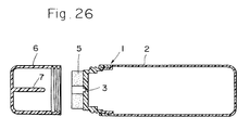
- container 1 formed of an resilient material is charged with liquid such as shoe polish.
- a forward member 4 having a liquid discharge vent 3 in the center thereof.
- Ring-shaped applicator member 5 of sponge is attached to the outside of said forward member 4.
- cap 6 is attached thereon while applicator is not in use such that the seal rod 7 of the cap 6 blocks the liquid discharge vent 3 with the result that the liquid will not be discharged out of the discharge vent 3.
- cap 6 is removed such that the inside liquid is squeezed out of the discharge vent 3 by pressing container 2 to soak into the applicator member 5 for application work.
- the technical problem is observed with the aforementioned prior art applicator 1; that is, it has the liquid discharge vent 3 which directly opens outwardly with the result that low viscosity liquid charged inside the container 2 can splash out when cap 6 is removed for use by jerking the container 2 or the liquid can shoot out to stain things therearound when the container 1 is pressed.
- cap 2 is first removed to press applicator member 1 onto an object to which the liquid is to be applied. Then, container 2 is pressed to force out the liquid therein such that the forced out liquid is prevented from leaking outside by being blocked by applicator member 5 of sponge or the like and the object to which the liquid is to be applied. It is also required that the liquid is carefully applied by allowing the liquid to soak into applicator member 5 while seeing to it that there is no leak or drip of the liquid. This procedure, however, makes the application work troublesome and there has been a problem in finding a liquid applicator easier to handle.
- Seal rod 7 of cap 6 is designed to block liquid discharge vent 3 in container 2 while in disuse, making it impossible to provide the applicator member 4 covering the liquid discharge member 5 with the result that low viscosity liquid is liable to splash outside.
- high viscosity liquid is used to prevent such liquid splash outside the applicator, even application of liquid is difficult in addition to the problem of increased liquid consumption.
- use of high viscosity liquid is impossible for some field of application.
- the applicator member S attached around the discharge vent 3 be made of sponge excellent in liquid absorbing capability such that there is no leak of liquid discharged out of the liquid discharge vent 3. This means that a brush which is poor in liquid absorbing capability is not suited for this purpose. Even if sponge is used for the applicator member 5, it ages with the passage of time to such an extent that fragments of damaged sponge caused by repeated use can stick to the object to which the liquid is to be applied, thereby marring the finishing surface thereof.
- applicators such as disclosed in Japanese Pat. Appln. Kokai Pub. No. 5-305529 and Japanese U.M. Appln. Kokai Pub. No. 5-31996 have tip end application members directly pressed to open the valve such that the liquid is discharged though the majority of the applicator members are formed of felt which is susceptible to aging with the passage of time with the result that repeated use thereof causes broken fragments of damaged applicator portion due to ageing can mar the finishing surface of the object which the liquid is to be applied or that the diameter or the width of the tip end of the applicator member may vary to allow unnecessary application of the liquid.
- Such applicator has the liquid discharged particularly from around the applicator member with the result that the liquid can stick to the object to which the liquid is to be applied before the applicator member absorbs the liquid, thus causing uneven application of the liquid.
- the present invention is made to solve the afore mentioned problems of the conventional applicators and has its objects that by removing the cap of the applicator to open the valve the liquid is directly supplied from the container to the object to which the liquid is to be applied that facility of the application work is accomplished while splashing out of the liquid is prevented and that the liquid applicator with assurance of constantly even liquid application is provided.
- the present invention essentially provides a liquid applicator which comprises a container body made of an resilient resin material, said container body being charged with a predetermined liquid therein; an intermediate shaft member hermetically attached to said container body at an open end thereof to close discharge vent formed therein, said intermediate shaft member further having a hollow shaft member in communication with said liquid discharge vent and integrally projecting outwardly therefrom; a forward shaft member press fitted to said intermediate shaft member and having a first communication passage into which said hollow shaft member is press fitted, said communication passage having a shouldered seal portion at a forward end thereof, said forward shaft member further having an applicator attachment hole which opens forwardly and a connecting passage to provide communication between said first communication passage and said applicator attachment hole; a valve body incorporated into said first communication passage to be normally urged against said shouldered seal portion to define a seal chamber separated from outside; and an applicator member fixedly inserted into said applicator attachment hole; whereby said valve body incorporated in said firs communication is urged against said shouldered seal portion
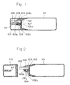
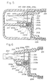
- container 101 made of an resilient material such as resin is charged with a predetermined fluid before intermediate shaft member 102 having liquid discharge vent 102a centrally formed is screwed or fused onto the longitudinal end opening of container 101. Further, forward shaft member 103 is press fit into or fused onto the tip end of said intermediate shaft member 102.
- hollow shaft member 102b communicating with the liquid discharge vent 102a is integrally formed to project therefrom.
- said forward shaft member 103 is engaged onto the intermediate shaft member 102, said hollow shaft 102b of the intermediate member 102 is press fit into communication passage 103a of the forward shaft member 103, thus defining seal chamber 104 between the tip end of hollow shaft 102b and communication passage 103a of forward shaft member 3.
- Valve body 105 such as a check ball is incorporated together with resilient body 106 such as a valve spring at the time of engaging said forward shaft member 103 onto intermediate shaft member 102. Said valve body 105 incorporated into seal chamber 104 is pressed against the shouldered small diameter seal portion 103b formed within said communication passage 103a to close said communication passage 103a such that the outside and inside of the container is separated.
- the face on the valve side of the shouldered small diameter seal portion 103b may be formed perpendicular, tapered or spherical to follow the contour of the valve body.
- applicator attachment hole 108 for applicator body into which applicator member 107 made of a material such as felt, sponge or brush is engaged.
- Counter-bored portion 108a is formed at the root portion of said applicator attachment hole 108 to engage flange portion 107a formed at the base of applicator member 107.
- communication passage 103c is defined which communicates from seal chamber 104 along hollow shaft 102b to counter-bored portion 108a of the attachment hole 108.
- valve body 105 incorporated into seal chamber 104 is pressed against shouldered seal portion 103b formed in communication passage 103a of forward shaft 103 to block, the liquid charged in container 101 flows through hollow shaft 102b to seal chamber 104 before it further flows from seal chamber 104 through connecting passage 103c formed along hollow shaft 102b to the counterbored portion 108a of the attachment hole 108.
- cap 110 to be attached to the forward portion of said container 101 is screwed onto the threaded portion 109 formed in the outside periphery of intermediate member 102.
- valve pushing rod 111 having a predetermined length to project into communication passage 103a in the forward shaft member 103. Therefore, when cap 110 is screwed onto the taped portion 109 of intermediate portion 102, valve pushing rod 111 of the cap 110 is inserted into communication passage 103a in the forward shaft member 103. Therefore, valve body 105 closing communication passage 103a is urged back against resilient member 6 to be pressed against tapered portion 102c formed in the tip of hollow shaft 102b with the result that the liquid flowing into seal chamber 104 through hollow shaft 102b is blocked.
- the valve side hem of the tapered portion 102c may be circular, rounded or shaped anyway to follow the shape of the valve body 105.
- cap 110 is kept attached to the tip end of container 110 while the applicator is not in use, in storage or during transit.
- valve 105 incorporated in seal chamber 104 is pressed against the tip end of hollow shaft 102b by valve pushing rod 111 such that fluid will not flow into seal chamber 104 blocked thereby. Therefore, even if container 101 is pressed or the inside pressure of container 101 increases due to the rise of ambient temperature, the fluid will not leak outside seal chamber 104.
- valve body 105 When cap 110 is removed from the tip end of container body 101 to use the applicator, the pressing of valve body 105 by valve pushing rod 111 is removed such that valve body 105 is pressed against shouldered seal portion 103b formed in communication passage 103a of forward shaft member 103 to separate the outside and the inside of said seal chamber 104.
- the liquid in seal chamber 104 is prevented from leaking outside while the fluid led from container 101 into seal chamber 104 flows through connecting passage 103c into counterbored portion 108a of applicator attachment hole 108. Therefore, the fluid having soaked into the applicator member 107 is applied to a desired surface of the object to be applied by holding container 101 to press the applicator member thereto and is continuously applied by keeping the container 101 pressed once in a while.
- valve body 105 incorporated into seal chamber 104 in this invention shall not be limited to a spherical ball but may be of configuration of a piston. It is preferred that said metal valve body is formed of metal. In this case, rust-resisting stainless steel is preferred.
- the valve body 105 may be of synthetic resin material including PP (polypropylene), HDPE (high density polyethylene), nylon, POM (polyathetal).
- Resilient member 106 such as the valve spring which presses the valve is in the form of a coil spring though the material thereof may be of rust-resisting stainless steel is preferred while synthetic resin is acceptable.
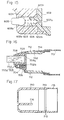
- Fig. 5 is a vertical sectional view of the principal portion of the second embodiment of the fluid applicator according to the present invention.
- Fig. 6 is a vertical sectional view of the state in which the cap is removed for use of the fluid applicator of Fig. 5.
- the similar numerals are allotted to the similar members to the first embodiment.
- recess 208c extending from said counter-bored portion 108a in forward shaft member 203 is formed to deepen the counter-bored portion 208a.
- block plug 212 having second connecting passage 212a which communicates communication passage 203c in forward shaft member 203.
- receiving hole 207b having a predetermined length is formed in the base portion of applicator member 207 to communicate with said second communication passage 212a in said block plug 212 to facilitate the introduction of the fluid into the applicator member 207.
- cap 210 of the applicator of the second embodiment is removed to use the applicator, the liquid discharged from container 201 into seal chamber 204 is led from connecting passage 203c of forward shaft member 203 through second communication passage 212a in the block plug 212 inserted into recessed portion 208c before the fluid is further admitted into the introduction hole 207b substantially centrally formed in application member 207 to soak into said application member 207.
- the fluid is easily absorbed into applicator member 207 without the concern of liquid dripping to assure good application performance.
- Fig. 7 is a vertical sectional view of the principal portion of the third embodiment of the fluid applicator of the present invention when not in use
- Fig. 8 is a vertical sectional view of the principal portion in use shown in Fig. 7 wherein similar numerals are used for similar members which are common to those in the first and second embodiments and explanation therefor is omitted.
- recess 308c extending from the counter-bored portion 308a is formed in forward shaft member 303 to deepen said counterbored portion in which flange 307a of applicator member 307 is inserted.
- Liquid absorbing member 313 is fitted in said recessed portion 308c such as a sponge which has excellent liquid retaining capability for the fluid.
- Fig. 9 is a vertical sectional view of the principal portion in disuse of the fourth embodiment of the fluid applicator according to the present invention.
- Fig. 10 shows a vertical sectional view of the principal portion thereof in use with the cap being removed.
- similar numbers are accorded to similar members which are common to the first and second embodiments while the explanation therefor will be omitted.
- the fourth embodiment according to the present invention is constructed such that recessed 408c is formed in forward shaft member 403 to extend from counter-bored portion 408a in a deepened form thereof for receiving flange portion 407a of applicator member 407 therein.
- block plug 412 which is formed with second connecting passage 412a to communicate with first connecting passage 403c in forward shaft member 403.
- Said applicator member 407 is formed with introduction hole 407b longitudinally over a predetermined distance from the base thereof to communicate with second communication passage 412a in block plug 412. Into said introduction hole 407b is engaged liquid absorbing member 414 of sponge having an excellent liquid retaining capability.
- the thus constructed applicator member 407 assures excellent liquid retaining capability for the fluid and provides a brush which well prevents the fluid from dripping.
- Fig. 11 is a vertical sectional view of the principal portion in disuse of the fifth embodiment of the fluid applicator according to the present invention and Fig. 12 is a vertical sectional view in use thereof with the cap shown in Fig. 11 being removed.
- similar numbers are accorded to similar members which are common to the first and second embodiments with explanation therefor being omitted.
- the fifth embodiment of the present invention is basically the same in construction as the second embodiment except for the fact that valve body 515 introduced in seal chamber 504 defined by the tip end of hollow shaft 502b of intermediate shaft member 502 and communication passage 503a in the forward shaft member 503 is in the form of a piston. Said valve body 515 is formed into a semi-spherical or conical configuration. When cap 510 is attached thereon, valve pushing rod 511 is inserted into communication passage 503a of forward shaft member 503 to push valve 515 such that said valve 515 resting within communication passage 503a is pressed against tapered portion 502c at the tip end of hollow shaft 502b to prevent the fluid from flowing into seal shaft 504 through hollow shaft 502b from container 501.
- valve body 515 When cap 510 is removed from the tip end of container 501 to use the applicator, the pressing of valve body 515 by valve pushing rod 511 is removed as shown in Fig. 12. As a result, valve body 515 is pressed by resilient member 506 against shouldered seal portion 503b formed in the communication chamber 503a of forward shaft member 503 to separate seal chamber 504 and the outside thereof, thereby preventing the fluid within seal chamber 504 from leaking outside while the fluid discharged from container 501 into seal chamber 504 is led through communication passage 503c to second communication passage 512a in block plug 512 engaged in recessed portion 508c where said fluid flows into introduction hole 507b substantially centrally formed in applicator member 507 to soak into the whole thereof.
- Fig. 13 is a vertical sectional view of the principal portion of the sixth embodiment of the liquid applicator according to the present invention while in disuse;
- Fig. 14 is an enlarged sectional view of the principal portion of Fig. 13;
- Fig. 15 is an enlarged view of the principal portion of Fig. 14 while not in use, when the cap is removed.
- container body 601 is made of an resilient material such as a synthetic resin or the like. After said container body 601 is charged with a predetermined liquid, intermediate shaft member 602 having a liquid discharge vent 602a formed off center or in a radially outward portion thereof is hermetically screwed, fused or engaged to the forward open end of container body 601 while the forward shaft member 603 is press fit or fused onto the forward end of said intermediate shaft member 602.
- hollow shaft member 602b integrally therewith.
- said hollow shaft member 602b of intermediate shaft member is press fit into communication passage 603a of said forward shaft member 603 to define seal chamber 604 between the tip end of said hollow shaft member 602b and communication passage 603a of forward shaft member 603.
- valve body 605 composed of spherical portion 605a and rod portion 605b is incorporated into sealed chamber 604 together with resilient member 606 in the form of a valve spring. Said valve body 605 incorporated into seal chamber is pressed against small diameter shouldered seal portion 603b formed in communication passage 603a to provide communication between said liquid discharge vent 602a and connecting passage 603c which is t be described later.
- valve side of said shouldered seal portion may be rectangular, tapered, or shaped to follow the contour of the valve body.
- Substantially centrally in said forward shaft member 603 is bored applicator attachment hole 608 to receive applicator 607 composed of felt, sponge or a brush.
- the base of said applicator 607 has a flange portion 607a which engages the counter-bore portion 608a formed at the rearward end of attachment hole 608.
- connecting passage 603c is defined to provide communication from sealed chamber 604 along the side of hollow shaft 602b projecting from intermediate shaft member 602 to counter-bored portion 608a in attachment hole 608.
- Valve body 605 incorporated in said communication passage 603a is pressed against shouldered seal portion to define seal chamber 604 in forward shaft member, thus opening said communication passage 603a (the state in which liquid discharge vent 602a and communication passage 603c are in communication with each other).
- the liquid charged in container 601 is discharged through hollow shaft 602b to seal chamber 604, where the fluid further continues to flow through connecting passage 603c defined along hollow shaft into counter-bored portion 608a of attachment hole 608.
- rod portion 605b is caused to project outside intermediate shaft member 602 as shown in Fig. 15.
- cap 610 to be attached to the for ward portion of said container body 601 is screwed onto threaded portion 609 formed on the outer periphery of intermediate shaft member 602 while valve operating portion 611 having a central recess therein to receive application member is fit inside said cap 610.
- valve operating portion 611 of cap 610 When cap 610 is screwed onto threaded portion 609 of intermediate shaft member 602, valve operating portion 611 of cap 610 receives applicator member 607 in said central recess 611a while rearward end 611b of valve operating portion 611 presses rod portion 5b of valve body 605 50 far having kept communication passage 604a open to push back said valve 605 against resilient body 606.
- valve operating portion 611 When cap 610 is screwed onto threaded portion 609 of intermediate shaft member 602, rearward end face 611b of valve operating portion 611 continues to contact and keep pressing rod portion 605b of valve body 605 since valve operating portion 611 is ring-shaped.
- Valve body 605 is eventually pressed against the tip end of hollow shaft 602b to block the flow of the fluid from hollow shaft 602b into seal chamber 604.
- cap 10 is attached onto the forward end of container 601 while in disuse, in custody or during transit, valve body 605 incorporated in communication passage 603a is pressed against the tip end of hollow shaft 602b to prevent the fluid from flowing thereinto.
- valve operating portion 611 When cap 610 is removed from the tip end of container 801 to use the applicator, the pressing on valve body 605 by valve operating portion 611 is removed such that valve 605 is now pressed against shouldered seal portion 603b of forward shaft member 603 by resilient member 606.
- the fluid which has soaked into applicator member 607 is subjected to application work by gripping container body 601 to press applicator 607 against a desired object surface and continued pressing of container body 601 allows application without intermission.
- applicator member 607 is centrally attached, thereby facilitating hand-writing work to user's purposes.
- valve body 604 incorporated within sealed chamber 604 shall not be limited to the configuration shown in the aforementioned embodiments and may be in the form of a piston.
- the material of valve body 605 may be of synthetic resin or metal, in which valve body 605 is preferred to be of rust-proof stainless steel.
- connecting passage 603c is made to provide a passage for the fluid charged in container body 605 which has been discharged therefrom to flow through hollow shaft 602b and sealed chamber 604 into counter-bored portion 608a of the applicator attachment hole 608, such connecting passage 603c may be formed to be led to a position close to the tip end of the applicator member 607 secured in applicator attachment hole 608 in forward shaft portion 603.
- the aforementioned embodiment assures that the liquid having soaked into the whole applicator 607 makes larger an area to be applied with the fluid in one application stroke while making the liquid retaining capacity larger to prevent the liquid from dripping outside even if a large quantity of liquid is discharged at one stroke. Therefore, extra liquid discharged toward applicator member 607 due to excessive pressure on container body 601 when the pressure on container body 601 is removed.
- cap is constructed to be attached onto the intermediate shaft member, said cap may attached to the tip end of the container body.
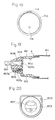
- Fig. 16 is a vertical sectional view of the principal portion of the applicator while in use of the seventh embodiment according to the present invention
- Fig. 17 is a vertical sectional view of the cap
- Fig. 18 is a side elevation of the cap.
- similar numerals are accorded to similar members which are common to the sixth embodiment.
- valve body 705 is made spherical while cap 710 is formed inside thereof with valve operating rod 716 to press valve body 705.
- cap 710 is formed with protuberance 713 which engages intermediate shaft member 702 by overriding protuberance 712 formed around the periphery of said intermediate shaft member 702.
- part of the outside periphery of container 701 is formed with axially elongated projection 714, which engages recess 715 formed in the inside wall of cap 710 in correspondence with said projection 714 so as to align the valve operating rod 716 with the position of valve body 705 or communication passage 703a) at the time of attaching cap 710 onto container 701.
- cap 710 is attached to container body 701 with said groove 715 and projection 714 in alignment with each other such that valve operating rod 716 presses rod portion 705b of valve body 705 to push back valve body 705 blocking communication passage 3a against resilient body 706.
- valve body 705 is pressed against the tip end of hollow shaft 702b with the result that the fluid flowing in from hollow shaft 702b to sealed chamber 704 is blocked.
- valve body 705 When cap 710 is removed from the tip end of container 701 to use the applicator, the pressing of valve body 705 by means of valve operating rod 716 is removed as shown in Fig. 16. In this situation, valve body 705 is pressed by resilient member 706 against shouldered seal portion 3b formed in communication passage 3a of the forward shaft member 3 to separate seal chamber 4 from outside thereof.
- Fig. 19 is a vertical sectional view of the principal portion of the third embodiment of the fluid applicator according to the present invention while in use;
- Fig. 20 is a side elevation of Fig. 19;
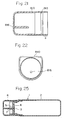
- Fig. 21 is a vertical sectional view of the cap;
- Fig. 22 is a side elevation of the cap.
- the eighth embodiment uses valve body 805 in spherical configuration as in the seventh embodiment and valve operating rod 816 attached to cap 810 to press said valve body 805.
- cap 810 is formed with protuberance 813 which engages intermediate shaft member 802 by overriding protuberance 812 formed around the periphery of said intermediate shaft member 802.
- part of the outside periphery of cap 710 is formed with axially elongated projection 714 which engages groove 715 in the inside wall of cap 810 in correspondence with said projection 714 so as to align valve operating rod 716 with the position of valve 705.
- portion A of intermediate shaft member 802 which engages cap 810 is shaped rectangular in the upper portion thereof and circular in the lower portion thereof.
- a of cap 810 corresponds to that of said portion A.
- valve operating rod 816 can be inserted into communication passage 803a with ease such that valve body 805 which closes communication passage 803a is pushed back against the force by resilient member 806.
- valve body 805 is eventually pressed against the tip end of hollow shaft 802b to block the liquid flowing through hollow shaft 802b into seal chamber 804.
- valve body 805 When cap 810 is removed from the tip end of container body 801 to use the applicator, the pressing on valve body 805 by means of valve operating portion 816 of valve body 805 is removed. As a result, valve body 805 is pressed against shouldered seal portion 803b formed in communication passage 803a of forward shaft member 803 by means of resilient body 806 thereby separating seal chamber 804 and outside thereof.
- the liquid in seal chamber 804 is prevented from leaking outside while the liquid which has flown into sealed chamber 804 from container body 801 is led through connecting passage 803c to counter-bored portion 808a of applicator attachment hole 808.
- the ninth embodiment is basically of the similar structure to that shown in Fig. 3.
- intermediate shaft member 902 and forward shaft member 903 are sequentially fitted onto container body 901.
- cap 910 is screwed onto the threaded portion 909 formed on the forward periphery of container body 901.
- said intermediate shaft member 902 is formed with hollow portion 902a extending into container body 901 at a position axially off center.
- forward shaft member 903 is formed with portion 903e which is fitted into said hollow portion 902a such that said portion 903e is formed with applicator member attachment hole 908.
- connecting passage 903c extends forwardly to form pocket 903d.
- the liquid applicator of the present invention is attached with a cap at the tip end thereof in disuse, in custody or during transit in which the valve body introduced in the sealed chamber is pressed by the pushing rod against the tip end of a hollow shaft such that the liquid is blocked to prevent from flowing into the sealed chamber with the result that accidental pressing of the container or any increase of inside pressure due to the rise of ambient temperature will not allow the fluid to leak outside.
- the cap While in use, the cap is removed from the tip end of the container to remove the pushing of the valve body by means of the valve pushing rod.
- This allows the valve body to be pressed by a resilient member against the shouldered seal portion formed in the communication passage in the forward shaft member. Then, the liquid in the sealed chamber is prevented from leaking outside while the liquid the liquid discharged from the container flows into the attachment hole through the communication passages. Therefore, the container is simply gripped and the applicator member is rubbed against the object surface such that the liquid which has soaked into the whole of the applicator member can be applied thereto while continuous application work is possible by pressing the container.
- the liquid applicator according to the present invention allows the liquid in the container to be supplied through the sealed chamber to be applied directly to the object as in use whereas the cap is attached thereto to block the passage of the liquid in disuse to assure the provision of a handy applicator regardless of the viscosity of the liquid.
- the liquid applicator according to the present invention is constructed such that said cap is screwed on the threaded portion of the intermediate shaft member with the liquid applicator being inserted into a recess in the valve operating portion of the cap while the valve operating portion constantly presses to block the communication of said liquid discharge vent; and said communication passage.
- said liquid discharge vent and said communication passage is placed into communication with each other.
- the liquid is allowed to be led through the communication passage along the hollow shaft member to the applicator attachment hole to which the applicator is attached. Therefore, it is possible to arrange applicator attachment hole and the applicator centrally in the intermediate shaft member. As a result, the applicator which is easy to write with and handy is provided.
- the liquid applicator according to the present invention is constructed such that the protuberance formed in the intermediate shaft member or in the container body is engaged with said groove in the cap to position said cap such that the valve operating rod is pressed against the valve body to separate said liquid discharge vent and said communication. Therefore, it is possible to arrange the applicator attachment hole and the applicator centrally in the intermediate shaft member like the applicator. As a result, the applicator which is easy to write with and handy is provided.
- the liquid applicator according to the present invention is constructed such that the inside surface of the cap and the periphery of the intermediate shaft member are asymmetrically shaped. Therefore, positioning is done in attaching the cap to the tip end of the container body or the intermediate shaft member and that the valve operating rod is caused to press the valve body to separate said liquid discharge vent and said communication passage. Therefore, it is possible to arrange the applicator arrangement hole and the applicator centrally in the intermediate shaft member explained in the foregoing. As a result, the applicator which is easy to write with and handy is provided.
- the invention according to the present invention is constructed such that the cap is attached to the tip end of the container when the applicator is not in use, in storage or during transit to cause the valve body to separate said liquid discharge vent and said communication passage, thereby preventing the liquid from leaking outside even if the container is pressed.
- the pressing of the valve body by means of valve operating rod is removed to press the valve body against the shouldered seal portion in the communication passage in the forward shaft member to bring the liquid discharge vent and the communication passage in communication with each other. Therefore, the liquid which has flown into sealed chamber is led through communication passage to the applicator attachment hole. Therefore, the liquid which has soaked into the applicator member is applied to a desired object surface by gripping the container body.
- the liquid applicator according to the present invention will not open its liquid discharge vent directly to the outside.
- the liquid in the container body is supplied directly to the applicator member after the sealed chamber.
- the cap is attached such that the passage for the liquid is blocked to assure that an excellent applicator is provided regardless of the liquid viscosity.
Landscapes
- Engineering & Computer Science (AREA)
- Mechanical Engineering (AREA)
- Coating Apparatus (AREA)
- Pens And Brushes (AREA)
Applications Claiming Priority (4)
| Application Number | Priority Date | Filing Date | Title |
|---|---|---|---|
| JP200233/94 | 1994-08-01 | ||
| JP20023394A JP3615571B2 (ja) | 1994-08-01 | 1994-08-01 | 流動体塗布具 |
| JP108301/95 | 1995-04-06 | ||
| JP10830195A JPH08275821A (ja) | 1995-04-06 | 1995-04-06 | 流動体塗布具 |
Publications (2)
| Publication Number | Publication Date |
|---|---|
| EP0695522A2 true EP0695522A2 (fr) | 1996-02-07 |
| EP0695522A3 EP0695522A3 (fr) | 1997-03-26 |
Family
ID=26448228
Family Applications (1)
| Application Number | Title | Priority Date | Filing Date |
|---|---|---|---|
| EP95305346A Withdrawn EP0695522A3 (fr) | 1994-08-01 | 1995-07-31 | Applicateur de liquide |
Country Status (2)
| Country | Link |
|---|---|
| US (1) | US5678941A (fr) |
| EP (1) | EP0695522A3 (fr) |
Cited By (5)
| Publication number | Priority date | Publication date | Assignee | Title |
|---|---|---|---|---|
| WO2008093372A1 (fr) * | 2007-01-31 | 2008-08-07 | Sixtem Life S.R.L. | Dispositif distributeur pour recipients pressurises pour l'application d'un refrigerant cryogenique |
| EP1704793A3 (fr) * | 2005-03-22 | 2009-05-20 | Young Kwang Byun | Boîtier pour produit cosmétique liquide |
| FR3047153A1 (fr) * | 2016-02-01 | 2017-08-04 | Jean Philippe Charlier | Perfectionnement au tube applicateur de liquide notamment de vernis a ongles |
| GB2562197A (en) * | 2017-01-30 | 2018-11-14 | Nerudia Ltd | Dispenser assembly |
| CN111825151A (zh) * | 2020-06-28 | 2020-10-27 | 中国科学院南京土壤研究所 | 层状金属氢氧化物的应用 |
Families Citing this family (6)
| Publication number | Priority date | Publication date | Assignee | Title |
|---|---|---|---|---|
| US6626600B1 (en) | 2000-09-13 | 2003-09-30 | Binney & Smith Inc. | Writing instrument |
| JP4842268B2 (ja) * | 2004-08-09 | 2011-12-21 | エイボン プロダクツ インコーポレーテッド | 化粧組成物を貯蔵かつ施与するための装置 |
| KR100529252B1 (ko) * | 2005-06-17 | 2005-11-17 | (주)지텍 | 액상분필 |
| KR100789290B1 (ko) * | 2006-09-28 | 2007-12-28 | 변영광 | 튜브형 액상 화장품용기 |
| US8215858B2 (en) * | 2008-03-20 | 2012-07-10 | Craig Carroll | Toggling cosmetic lacquer dispenser and delivery |
| KR100857177B1 (ko) * | 2008-05-23 | 2008-09-08 | (주)에스엔피월드 | 액상 화장용기 |
Citations (2)
| Publication number | Priority date | Publication date | Assignee | Title |
|---|---|---|---|---|
| JPH0531996U (ja) | 1991-10-07 | 1993-04-27 | 三菱鉛筆株式会社 | 流動体塗布具 |
| JPH05305529A (ja) | 1992-04-30 | 1993-11-19 | Pentel Kk | 弁付塗布具の金属製管状先体の製造方法 |
Family Cites Families (15)
| Publication number | Priority date | Publication date | Assignee | Title |
|---|---|---|---|---|
| US675699A (en) * | 1900-09-01 | 1901-06-04 | Paul E Wirt | Fountain-pen. |
| US978419A (en) * | 1908-10-31 | 1910-12-13 | Paul E Wirt | Fountain-pen. |
| US1079228A (en) * | 1913-03-13 | 1913-11-18 | Thomas De La Rue & Company Ltd | Fountain-pen. |
| US1812229A (en) * | 1929-12-23 | 1931-06-30 | Charles S Merrill | Non-leaking fountain pen |
| US2096708A (en) * | 1935-12-02 | 1937-10-26 | Sheaffer W A Pen Co | Fountain pen |
| DE691765C (de) * | 1936-12-18 | 1940-06-05 | A W Faber Castell Bleistift Fa | chreibfeder absperrenden Verschlussglied |
| CH245028A (de) * | 1944-03-10 | 1946-10-31 | Christen Ernst | Taschen-Füllflüssigkeitsgerät, insbesondere für Fleckenwasser, Parfums usw. |
| US3075229A (en) * | 1958-12-08 | 1963-01-29 | L S Kaufman & Sons Inc | Liquid shoe polish applier |
| US3129452A (en) * | 1962-12-03 | 1964-04-21 | Glide O Matic Corp | Dauber having an internal compressed body |
| US3331094A (en) * | 1964-12-07 | 1967-07-18 | Schwartzman Gilbert | Applicator having movable head |
| US3400997A (en) * | 1965-03-26 | 1968-09-10 | Schwartzman Gilbert | Squeeze container applicator |
| US4368746A (en) * | 1981-06-01 | 1983-01-18 | Spatz Steven D | Valved cosmetic applicator |
| DE8907135U1 (de) * | 1989-06-10 | 1990-10-11 | Rotring-Werke Riepe Kg, 2000 Hamburg | Auftragsvorrichtung für flüssiges oder pastöses Gut, insbesondere Nagellack |
| DE4101785A1 (de) * | 1991-01-18 | 1992-07-23 | Ahrens Hans Joachim Dipl Phys | Auftragsstift fuer fluessigkeiten |
| JPH0531996A (ja) * | 1991-07-31 | 1993-02-09 | Mitsubishi Heavy Ind Ltd | 印書制御方法 |
-
1995
- 1995-07-27 US US08/508,208 patent/US5678941A/en not_active Expired - Fee Related
- 1995-07-31 EP EP95305346A patent/EP0695522A3/fr not_active Withdrawn
Patent Citations (2)
| Publication number | Priority date | Publication date | Assignee | Title |
|---|---|---|---|---|
| JPH0531996U (ja) | 1991-10-07 | 1993-04-27 | 三菱鉛筆株式会社 | 流動体塗布具 |
| JPH05305529A (ja) | 1992-04-30 | 1993-11-19 | Pentel Kk | 弁付塗布具の金属製管状先体の製造方法 |
Cited By (5)
| Publication number | Priority date | Publication date | Assignee | Title |
|---|---|---|---|---|
| EP1704793A3 (fr) * | 2005-03-22 | 2009-05-20 | Young Kwang Byun | Boîtier pour produit cosmétique liquide |
| WO2008093372A1 (fr) * | 2007-01-31 | 2008-08-07 | Sixtem Life S.R.L. | Dispositif distributeur pour recipients pressurises pour l'application d'un refrigerant cryogenique |
| FR3047153A1 (fr) * | 2016-02-01 | 2017-08-04 | Jean Philippe Charlier | Perfectionnement au tube applicateur de liquide notamment de vernis a ongles |
| GB2562197A (en) * | 2017-01-30 | 2018-11-14 | Nerudia Ltd | Dispenser assembly |
| CN111825151A (zh) * | 2020-06-28 | 2020-10-27 | 中国科学院南京土壤研究所 | 层状金属氢氧化物的应用 |
Also Published As
| Publication number | Publication date |
|---|---|
| US5678941A (en) | 1997-10-21 |
| EP0695522A3 (fr) | 1997-03-26 |
Similar Documents
| Publication | Publication Date | Title |
|---|---|---|
| US6641320B1 (en) | Applicator tip for liquid applicator device | |
| US5803640A (en) | Applicator | |
| US6059474A (en) | Multi-purpose nail enamel applicator | |
| US5678941A (en) | Liquid applicator | |
| US5636931A (en) | Applicator device with a perforated piston | |
| KR100320764B1 (ko) | 도포기 | |
| US7021851B1 (en) | Toothbrush incorporating dentifrice dispenser | |
| EP0737155B1 (fr) | Fermeture thermoplastique d'un recipient de fluide et systeme de remplissage d'un reservoir de fluide | |
| US4040753A (en) | Applicator instrument | |
| EP0622035A1 (fr) | Ensemble applicateur d'un produit liquide, notamment cosmétiques | |
| US6328040B1 (en) | Nail polish pen having spare tips | |
| CA2798015C (fr) | Dispositif applicateur de liquide | |
| US7172360B2 (en) | Art instrument | |
| EP1023856A3 (fr) | Réceptacle pour recevoir des materiaux fluides, gélifiés ou pâteux | |
| US6428235B1 (en) | Liquid applicator having ink color identification | |
| US7086799B1 (en) | Marker | |
| US4469464A (en) | Ink pad applicator | |
| US3426888A (en) | Coloring set | |
| JP4269104B2 (ja) | 塗布具 | |
| JP3926008B2 (ja) | 塗布具 | |
| US5511592A (en) | Spare bottle for an ink refilling of piston-type fountain pens or of writing implements fitted with an ink reservoir and an ink conducting system | |
| CA2161433A1 (fr) | Cartouche de fluide et methode de remplissage connexe | |
| JPS6337100Y2 (fr) | ||
| JPH0838982A (ja) | 流動体塗布具 | |
| JP3926421B2 (ja) | 筆記具 |
Legal Events
| Date | Code | Title | Description |
|---|---|---|---|
| PUAI | Public reference made under article 153(3) epc to a published international application that has entered the european phase |
Free format text: ORIGINAL CODE: 0009012 |
|
| AK | Designated contracting states |
Kind code of ref document: A2 Designated state(s): DE FR GB IT |
|
| PUAL | Search report despatched |
Free format text: ORIGINAL CODE: 0009013 |
|
| AK | Designated contracting states |
Kind code of ref document: A3 Designated state(s): DE FR GB IT |
|
| 17P | Request for examination filed |
Effective date: 19970423 |
|
| 17Q | First examination report despatched |
Effective date: 19990507 |
|
| STAA | Information on the status of an ep patent application or granted ep patent |
Free format text: STATUS: THE APPLICATION IS DEEMED TO BE WITHDRAWN |
|
| 18D | Application deemed to be withdrawn |
Effective date: 19990918 |