EP0695554A2 - Seringue automatique - Google Patents
Seringue automatique Download PDFInfo
- Publication number
- EP0695554A2 EP0695554A2 EP95250185A EP95250185A EP0695554A2 EP 0695554 A2 EP0695554 A2 EP 0695554A2 EP 95250185 A EP95250185 A EP 95250185A EP 95250185 A EP95250185 A EP 95250185A EP 0695554 A2 EP0695554 A2 EP 0695554A2
- Authority
- EP
- European Patent Office
- Prior art keywords
- cartridge
- plunger
- medicament
- seal
- rearward
- Prior art date
- Legal status (The legal status is an assumption and is not a legal conclusion. Google has not performed a legal analysis and makes no representation as to the accuracy of the status listed.)
- Granted
Links
- 239000003814 drug Substances 0.000 claims abstract description 97
- 238000004891 communication Methods 0.000 claims abstract description 14
- 239000007788 liquid Substances 0.000 claims abstract description 14
- 239000012530 fluid Substances 0.000 claims abstract description 9
- 238000000034 method Methods 0.000 claims description 17
- 230000002093 peripheral effect Effects 0.000 claims description 16
- 230000004044 response Effects 0.000 claims description 13
- 238000002347 injection Methods 0.000 claims description 11
- 239000007924 injection Substances 0.000 claims description 11
- 210000002445 nipple Anatomy 0.000 description 16
- 210000003811 finger Anatomy 0.000 description 11
- 125000006850 spacer group Chemical group 0.000 description 6
- 238000004519 manufacturing process Methods 0.000 description 3
- 239000002184 metal Substances 0.000 description 3
- 239000004033 plastic Substances 0.000 description 3
- 238000007789 sealing Methods 0.000 description 3
- 230000008901 benefit Effects 0.000 description 2
- 239000013013 elastic material Substances 0.000 description 2
- 239000011521 glass Substances 0.000 description 2
- 230000007246 mechanism Effects 0.000 description 2
- 230000001681 protective effect Effects 0.000 description 2
- 230000000717 retained effect Effects 0.000 description 2
- 239000006096 absorbing agent Substances 0.000 description 1
- 230000009471 action Effects 0.000 description 1
- 230000003213 activating effect Effects 0.000 description 1
- 230000008859 change Effects 0.000 description 1
- 230000000694 effects Effects 0.000 description 1
- 210000003414 extremity Anatomy 0.000 description 1
- 239000000122 growth hormone Substances 0.000 description 1
- 230000036512 infertility Effects 0.000 description 1
- 239000000463 material Substances 0.000 description 1
- 230000004048 modification Effects 0.000 description 1
- 238000012986 modification Methods 0.000 description 1
- 230000000149 penetrating effect Effects 0.000 description 1
- 230000035939 shock Effects 0.000 description 1
- 239000000126 substance Substances 0.000 description 1
- 210000003813 thumb Anatomy 0.000 description 1
- 230000007704 transition Effects 0.000 description 1
Images


Classifications
-
- A—HUMAN NECESSITIES
- A61—MEDICAL OR VETERINARY SCIENCE; HYGIENE
- A61M—DEVICES FOR INTRODUCING MEDIA INTO, OR ONTO, THE BODY; DEVICES FOR TRANSDUCING BODY MEDIA OR FOR TAKING MEDIA FROM THE BODY; DEVICES FOR PRODUCING OR ENDING SLEEP OR STUPOR
- A61M5/00—Devices for bringing media into the body in a subcutaneous, intra-vascular or intramuscular way; Accessories therefor, e.g. filling or cleaning devices, arm-rests
- A61M5/178—Syringes
- A61M5/20—Automatic syringes, e.g. with automatically actuated piston rod, with automatic needle injection, filling automatically
- A61M5/2033—Spring-loaded one-shot injectors with or without automatic needle insertion
-
- A—HUMAN NECESSITIES
- A61—MEDICAL OR VETERINARY SCIENCE; HYGIENE
- A61M—DEVICES FOR INTRODUCING MEDIA INTO, OR ONTO, THE BODY; DEVICES FOR TRANSDUCING BODY MEDIA OR FOR TAKING MEDIA FROM THE BODY; DEVICES FOR PRODUCING OR ENDING SLEEP OR STUPOR
- A61M5/00—Devices for bringing media into the body in a subcutaneous, intra-vascular or intramuscular way; Accessories therefor, e.g. filling or cleaning devices, arm-rests
- A61M5/178—Syringes
- A61M5/31—Details
- A61M5/315—Pistons; Piston-rods; Guiding, blocking or restricting the movement of the rod or piston; Appliances on the rod for facilitating dosing ; Dosing mechanisms
- A61M5/31511—Piston or piston-rod constructions, e.g. connection of piston with piston-rod
-
- A—HUMAN NECESSITIES
- A61—MEDICAL OR VETERINARY SCIENCE; HYGIENE
- A61M—DEVICES FOR INTRODUCING MEDIA INTO, OR ONTO, THE BODY; DEVICES FOR TRANSDUCING BODY MEDIA OR FOR TAKING MEDIA FROM THE BODY; DEVICES FOR PRODUCING OR ENDING SLEEP OR STUPOR
- A61M5/00—Devices for bringing media into the body in a subcutaneous, intra-vascular or intramuscular way; Accessories therefor, e.g. filling or cleaning devices, arm-rests
- A61M5/178—Syringes
- A61M5/31—Details
- A61M5/3129—Syringe barrels
- A61M2005/3132—Syringe barrels having flow passages for injection agents at the distal end of the barrel to bypass a sealing stopper after its displacement to this end due to internal pressure increase
-
- A—HUMAN NECESSITIES
- A61—MEDICAL OR VETERINARY SCIENCE; HYGIENE
- A61M—DEVICES FOR INTRODUCING MEDIA INTO, OR ONTO, THE BODY; DEVICES FOR TRANSDUCING BODY MEDIA OR FOR TAKING MEDIA FROM THE BODY; DEVICES FOR PRODUCING OR ENDING SLEEP OR STUPOR
- A61M5/00—Devices for bringing media into the body in a subcutaneous, intra-vascular or intramuscular way; Accessories therefor, e.g. filling or cleaning devices, arm-rests
- A61M5/178—Syringes
- A61M5/31—Details
- A61M5/315—Pistons; Piston-rods; Guiding, blocking or restricting the movement of the rod or piston; Appliances on the rod for facilitating dosing ; Dosing mechanisms
- A61M5/31511—Piston or piston-rod constructions, e.g. connection of piston with piston-rod
- A61M2005/31516—Piston or piston-rod constructions, e.g. connection of piston with piston-rod reducing dead-space in the syringe barrel after delivery
-
- A—HUMAN NECESSITIES
- A61—MEDICAL OR VETERINARY SCIENCE; HYGIENE
- A61M—DEVICES FOR INTRODUCING MEDIA INTO, OR ONTO, THE BODY; DEVICES FOR TRANSDUCING BODY MEDIA OR FOR TAKING MEDIA FROM THE BODY; DEVICES FOR PRODUCING OR ENDING SLEEP OR STUPOR
- A61M5/00—Devices for bringing media into the body in a subcutaneous, intra-vascular or intramuscular way; Accessories therefor, e.g. filling or cleaning devices, arm-rests
- A61M5/178—Syringes
- A61M5/24—Ampoule syringes, i.e. syringes with needle for use in combination with replaceable ampoules or carpules, e.g. automatic
Definitions
- This invention relates to medicament injection devices, and in particular, injection devices which are especially adapted to dispense substantially all of the medicament contained therein.
- an automatic injector is a device for enabling an individual to self-administer a dosage of a liquid medicament.
- An advantage of automatic injectors is that they contain a measured dosage of a liquid medicament in a sealed sterile condition capable of storage in such condition for extensive periods of non-use, during which period immediate injection of the stored dosage may be accomplished at any time.
- an automatic injector includes a needle normally stored and concealed within a rigid outer housing. Also contained in the housing is a container or cartridge for containing the dose of medicament. A movable plunger rearwardly confines the medicament within the cartridge, and when a releasable spring assembly carried by the housing is released, the needle projects from a forward end of the housing, and the plunger is forced through the cartridge to displace the medicament therefrom through the needle and into the flesh of the user.
- the medicament cartridge is normally made from a glass, metal or plastic material.
- a "dental cartridge” which is a standard sleeve-like cartridge that is manufactured in bulk quantities for the medical industry.
- Dental cartridges are used in various applications as shown, for example, by U.S. Patent Nos. 3,413,974; 3,368,557; 3,678,931; 3,825,003; 4,445,895; 5,226,895 and 5,226,896.
- dental cartridges are mass produced, they are significantly less expensive than other types of cartridges, and it is thus desirable to incorporate them into automatic injectors.
- the use of dental cartridge shaped cartridges in automatic injectors is also advantageous since they can easily be filled with medicament by standard automatic filling machines.
- a problem associated with the use of such dental cartridges is that the forward portion thereof has a relatively reduced inner diameter relative to the rearward portion thereof.
- the plunger which travels forwardly through the cartridge is unable to fully dispense the portion of medicament which is disposed at the forwardmost portion in the cartridge.
- a small percentage of the medicament within the cartridge is effectively wasted.
- the expense associated with the wasted medicament is oftentimes very significant, especially when more costly medicaments such as human growth hormones are used.
- an automatic injector having a plunger with a forward portion thereof shaped to enter the narrowed diameter portion of the cartridge to thereby displace the liquid medicament therefrom through the needle.
- plungers have been ineffective in accomplishing their intended result. More particularly, plungers thus constructed have been unable to reach the forwardmost end of the cartridge, as liquid trapped between the plunger and an inwardly extending shoulder of the cartridge, which connects the forward and rearward portions of the cartridge, serves to hydraulically lock the piston in place a predetermined distance before reaching the forwardmost end of the cartridge, the limited biasing force of the spring assembly being insufficient to overcome such hydraulic lock.
- the present invention provides an automatic injector comprising a housing having a tubular cartridge disposed therein.
- the cartridge has a rearward portion thereof with a predetermined inner diameter and an inwardly extending shoulder connecting the rearward portion of the cartridge to a forward portion of the cartridge.
- the forward portion of the cartridge has a relatively smaller inner diameter than the predetermined diameter of the rearward portion of the cartridge.
- a liquid medicament is normally disposed in the cartridge, and a needle disposed within the housing is adapted to communicate with the medicament through a forward end of the cartridge to dispense the medicament in response to a predetermined actuating procedure.
- a plunger disposed within the cartridge rearwardly confines the medicament therein.
- the plunger has a rearward portion with a diameter at least as great as the predetermined inner diameter of the rearward portion of the cartridge and is movable forwardly through the cartridge in slidingly sealed relation with respect thereto to displace the medicament through the needle.
- the plunger has a forward portion thereof which has a relatively reduced diameter as compared to the rearward portion of the plunger.
- the forward portion of the plunger is shaped (1) to enter the forward portion of the cartridge to displace medicament therefrom through the needle, and (2) to maintain fluid communication between the forward end of the cartridge through which the needle communicates with the medicament, and a space within the cartridge between the plunger and the inwardly extending shoulder of the cartridge so as to dispense medicament from the cartridge until the plunger engages either the shoulder or the forward end of the cartridge.
- a releasable energy source is constructed and arranged to move the plunger forwardly through the cartridge to dispense medicament through the needle in response to the predetermined actuating procedure.
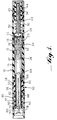
- Figure 1 is a longitudinal view, partly in section, of a first embodiment showing an automatic injector embodying the principles of the present invention.
- Figure 2 is an enlarged longitudinal sectional view of a portion of the injector of Figure 1, including a sectional view of the plunger of the present invention in an operative position.
- Figure 3 is a perspective side view of the plunger of the present invention according to the first embodiment.
- Figure 4 is a perspective front view of the plunger of the present invention according to the first embodiment.
- Figure 5 is a sectional view similar to Figure 2, but showing a second embodiment of the present invention.
- Figure 6 is a sectional view similar to Figure 2, but showing yet another embodiment of the present invention.
- Figure 1 is a longitudinal view, partly in section, showing an embodiment of an automatic injector according to the present invention.
- the injector about to be described is merely illustrative in that the plunger of the present invention can be used in virtually any injection device which utilizes a medicament container having a necked down forward portion, often referred to in the art as a "dental cartridge.”
- the actuating procedure described herein with respect to the disclosed injector is also illustrative, and would differ according to the particular injection device used.
- the injector of the present invention comprises a cylindrical outer housing or body 10. Disposed within the body 10 is a generally cylindrical medicament container in the form of a dental cartridge 12 which is open at its rearward end, and necked down at its forward end.
- the cartridge 12 is preferably made of glass, but can also be made of plastic or metal.
- the main portion 14 of the container or cartridge 12 extends rearwardly of the forward necked down forward portion 16 and has a predetermined inner diameter which is larger than the inner diameter of the necked down forward portion. These portions can be more clearly discerned in FIG. 2.
- the cartridge has an inwardly extending peripheral shoulder 18 which connects the main rearward portion of the cartridge with the smaller diameter forward portion of the cartridge.
- the forwardmost end (generally indicated at 24) of the cartridge has a radially outwardly extending flange 20 which receives a seal member 22 to close off the forward end.
- the seal member 22 is peripherally secured to the flange 20 at the forward end of the dental cartridge by means of an annular metallic clamping ring 26.
- a plunger 28 which is constructed in accordance with the principles of the present invention and described in greater detail later in the specification, closes the open rearward end of the cartridge 12 and is mounted therein for forward sliding movement in sealing relation with the interior surface thereof.
- the plunger is made of an elastic material such as rubber, but can also be made of a metal or plastic structure having an annular groove in which a resilient sealing "O" ring can be provided for sealing against the interior surface of the cartridge.
- This type of configuration is desirable, for example, in typical needle-less type injectors which require a substantial force to impact the rearward surface of the plunger to dispense medicament beneath the skin without a needle by virtue of the shear force of medicament
- a slidable needle hub assembly 30 receives the forward end of the cartridge 12, including clamp ring 26, in sliding telescopic relation.
- the needle hub assembly 30 has a substantially narrowed diameter forward portion 32 thereof disposed in surrounding relation to a needle 34.
- the needle 34 is secured at a central peripheral portion thereof to the hub assembly 30. Forward movement of the cartridge 12 causes the rearward end of the needle to pierce the seal member 22 through the center of the annular clamp ring 26 to establish communication with a charge of medicament 36 contained in the cartridge through the forward end 24 of the cartridge during an injection operation.
- a cover member 40 is disposed in surrounding relation to the forward portion of the needle and is spring biased by coil spring 42 to move forwardly in protective relation over the needle after an injection operation wherein the needle projects from the forward end of the device.
- a similar cover member and spring assembly is disclosed in U.S. Patent No. 5,295,965, hereby incorporated by reference. Additionally, it can be appreciated that the forward portion of the needle may be covered by a protective sheath 44 to maintain the sterility of the needle and to act as a shock absorber for the cartridge as the cartridge is moved forwardly towards the front end of the body during an injection procedure.
- a similar sheath is disclosed in U.S. Patent No. 3,882,863, hereby incorporated by reference.
- a releasable spring assembly 50 includes a main rearward tubular housing member 52 having a forward annular ridge 54 formed on the exterior periphery thereof in rearwardly spaced relation to the forward end thereof and a rearward ridge 56 of slightly greater exterior diameter disposed in rearwardly spaced relation with respect to the forward ridge 54.
- the body 10 has the rearward interior periphery formed with an annular groove 58 so as to enable the rearward end portion of body 10 to be moved rearwardly over the forward end portion of the tubular housing member 52 of spring assembly 50 so as to be retained therein in a position in which the rearward extremity of the body 10 engages the forward surface of rearward annular ridge 56.
- the tubular housing member 52 of spring assembly 50 is formed with an interior annular flange 60 spaced slightly inwardly from the rearward end thereof.
- the forward surface of the annular flange 60 is adapted to be engaged by a rearward volute of a coil spring 62 forming a part of the stressed spring assembly 50.
- Coil spring 62 operates as a releasable energy source for the injector of the present invention. It is understood that the present invention is not limited to the use of a coil spring and that any releasable energy source, such as an air spring, or chemical expansion reaction, may be used.
- the forward volute of the coil spring 62 engages a rearwardly facing surface of a forward flange 64 of a collet member, generally indicated at 66 (not shown in section).
- a spacer member 67 is optionally provided between the forward flange 64 of the collet and the plunger 28 .
- the spacer member permits the position of the plunger 28 within the cartridge to be controlled to determine the volume of the medicament chamber and thus the quantity of medicament carried in the chamber as disclosed in U.S. Patent No. 4,031,893, hereby incorporated by reference. If the spacer is not provided, the collet may be extended so that the forward end thereof makes direct contact with the plunger.
- the collet member 66 extends rearwardly from the forward flange 64 thereof within the coil spring 62.
- the rearward end portion of the collet member 66 is split so as to form a plurality (two) of rearwardly extending spring fingers 68.
- the rearward peripheral portion of the fingers 68 are formed with radially outwardly extending arcuate flanges presenting forwarding facing locking surfaces 74 which are adapted to engage along a generally radially extending plane with the rearwardly facing surface of the interior annular flange 60 of the housing member 52.
- a safety actuating pin member is disposed in cooperating relation with the resilient fingers 68 in a storage position and includes a forward portion 78 which extends inwardly between the resilient fingers 68.
- the safety actuating member 76 also includes an intermediate portion 80 of a reduced diameter with respect to the forward portion 78, there being a frustoconical transition between the two portions.
- the larger forward portion 78 extending between fingers 68 prevents the fingers from moving radially inwardly toward one another, thereby maintaining the locking surfaces 74 of the spring fingers 68 in engagement with the rearwardly facing locking surfaces of flange 60.
- coil spring 62 is retained in a stressed condition between the forward flange 64 of the collet member 66 and the forwardly facing surface of the interior flange 60 of housing member 52.
- cap structure 88 when in its storage position, covers actuating member 76.
- the cap structure 88 is removed, and the user grasps body 10 in one hand and places the forward end of the injector against the portion of flesh to be injected.
- the safety actuating pin member 76 is moved forwardly by a thumb or other finger so that the forward larger portion 78 of the actuating member 76 is moved into a position at which the interior portion of the fingers are shaped to more easily accommodate it.
- the narrowed diameter intermediate portion is also moved into the fingers and permits the fingers to flex to an extent sufficient such that the locking surfaces 74 are moved off of the flange 60, allowing the collet member 66 to move forwardly under the action of the spring 62.
- the collet 66 (and spacer 67 if provided) continues to move forwardly while the safety actuating pin member 76 is left behind in captured relation by the tubular housing member 52.
- the collet member 66 or spacer 67 during its forward movement is forced against the rearward surface of plunger 28.
- This in turn causes the entire cartridge 12 to move forwardly within the body 10 so that the forward end of the needle 34 projects from the forward end of the injector (while compressing sheath 44 and spring 42) and the rearward end of the needle pierces the seal member 22 to establish communication with the medicament through the forward end of the cartridge.
- the continued force of the collet member 66 and spacer 67 act to move the plunger 28 forwardly through the container 12. This movement of the plunger 28 pressurizes the liquid medicament 36 and begins to force it through the needle 34.
- the plunger 28 is made from an elastic material and has a rearward portion 100 with an outer diameter as defined by radial ridges 108 sized to form a seal with the inner surface 102 of the rearward portion 14 of the cartridge.
- the rearward portion 100 of plunger 28 has a diameter which is slightly greater than the predetermined inner diameter of the rearward portion of the cartridge when the plunger is not peripherally compressed by the inner surface 102. This permits the plunger to move in slidingly sealed relation with respect to the inner surface of the rearward portion of the cartridge to displace the medicament through the needle 34.
- the plunger has a forward portion 104 thereof being of a relatively reduced diameter than the rearward portion 100.
- the forward portion 104 is shaped to enter the forward narrowed diameter portion 16 of the cartridge to displace medicament contained therein though the needle. It is preferable for the forward portion 104 to have a length substantially equal to the necked down forward portion 16 so that when it enters the forward portion 16, it comes into close proximity or, most preferably, into abutment with seal member 22 to substantially displace all of the medicament from the cartridge.
- the forward portion 104 (or “nipple”) is particularly shaped to maintain fluid communication between the space at the forward end (see, generally, numeral 24) of the cartridge where the rearward end of the needle communicates with the medicament and a space (see, generally, numeral 106) formed within the cartridge between the plunger 28 and the inwardly extending shoulder 18 of the cartridge. More specifically, the plunger 28 continues its forward movement within the cartridge until it is in close proximity with the forward narrowed diameter portion 16 of the cartridge.
- the forward portion 104 of the plunger is shaped so that when it enters the narrowed diameter forward portion 16 of the cartridge, it does not form a seal with respect thereto which cuts off fluid communication between the space at the forward end 24 of the cartridge through which the needle communicates (e.g., between plunger 28 and seal 22) and the space 106 between the shoulder 18 of the cartridge and the plunger 28.
- the plungers which have been provided are problematic in that they are not particularly shaped to rid the medicament disposed in the narrowed diameter portion 16 of the cartridge.
- the nipple does not contact the forward seal to expel as much medicament as possible.
- the plungers which do provide an extended nipple heretofore such plungers have been problematic in that the nipples thereof seal the space shown at the forward end 24 of the injector from the space 106 before the nipple is permitted to fully enter the forward portion of the cartridge and displace the medicament therefrom.
- the seal formed in such fashion causes the medicament contained in the space 106 to become trapped therein and act to hydraulically lock the plunger in place and prevent it from moving forwardly through the cartridge to the greatest extent possible, which extent would be such that the forwardmost surface 110 of the nipple engages the seal member 22, or such that an arcuate annular shoulder 112 forming a transitional portion of the plunger between the rearward portion 100 and nipple portion 104 engages the shoulder 18 of the cartridge.
- the forward portion 104 of the plunger accomplishes the intended function of allowing the plunger to move forwardly to the greatest extent possible by being provided with at least one axially extending groove 116 which permits the space at forward end 24 of the cartridge and the space 106 to communicate therethrough to prevent hydraulic lock. It is preferred that the at least one axially extending groove be disposed in an outer peripheral surface of the plunger.
- the axially extending grooves can be provided as bores through more central portions of the forward reduced diameter portion of the plunger.
- the bores could extend from forward surface 110 (see, FIG. 2) axially rearwardly through the nipple and then extend radially to exit at a more rearward portion of the plunger, e.g. at arcuate annular shoulder 112, so that the space at the forward end 24 and the space 106 can communicate.
- the nipple portion of the plunger could simply have a sufficiently reduced outer diameter as compared to those known in the prior art to permit continuous communication between the two spaces until annular shoulder 112 of the plunger engages annular shoulder 18 of the cartridge, or until the forwardmost surface 110 of the plunger engages the seal 22 or rearward end of the needle 34. It such embodiment, it is preferred for the outer diameter of the nipple to be sufficiently reduced in size so that it does not make contact with the inner surface of the forward portion 16 of the cartridge.
- peripheral grooves 116 extend substantially along the entire length of the nipple portion of the plunger. It may also be desirable to extend such peripheral grooves onto the annular shoulder portion 112 of the plunger 22, as shown in Figure 4. Such grooves provided on the shoulder portion would extend substantially radially rather than axially. The grooves may also be provided in the forwardmost surface 110, as also shown in Figure 4.
- the nipple portion of the plunger be provided with a central bore 120 extending at least slightly into the forwardmost surface 110 so that the nipple can receive the rearward end of the needle when the nipple reaches its forwardmost point of travel (i.e., when it engages seal 22 or shoulder 18).
- the flow of medicament into the rearward end of the needle is maintained at all times.
- the plunger 128 provided is shaped more like a conventional plunger in that the nipple portion thereof does not extend substantially into the necked down region of the cartridge.
- the seal 122 provided at the forward end of the cartridge has a "top-hat” configuration and extends substantially into the necked down region to prevent medicament from entering said region. As can be appreciated from Figure 6, this configuration also prevents medicament from being wasted.
Landscapes
- Health & Medical Sciences (AREA)
- Vascular Medicine (AREA)
- Engineering & Computer Science (AREA)
- Anesthesiology (AREA)
- Biomedical Technology (AREA)
- Heart & Thoracic Surgery (AREA)
- Hematology (AREA)
- Life Sciences & Earth Sciences (AREA)
- Animal Behavior & Ethology (AREA)
- General Health & Medical Sciences (AREA)
- Public Health (AREA)
- Veterinary Medicine (AREA)
- Infusion, Injection, And Reservoir Apparatuses (AREA)
Applications Claiming Priority (2)
| Application Number | Priority Date | Filing Date | Title |
|---|---|---|---|
| US28088494A | 1994-07-27 | 1994-07-27 | |
| US280884 | 1994-07-27 |
Publications (3)
| Publication Number | Publication Date |
|---|---|
| EP0695554A2 true EP0695554A2 (fr) | 1996-02-07 |
| EP0695554A3 EP0695554A3 (fr) | 1996-05-08 |
| EP0695554B1 EP0695554B1 (fr) | 1999-01-07 |
Family
ID=23075007
Family Applications (1)
| Application Number | Title | Priority Date | Filing Date |
|---|---|---|---|
| EP95250185A Expired - Lifetime EP0695554B1 (fr) | 1994-07-27 | 1995-07-27 | Seringue automatique |
Country Status (5)
| Country | Link |
|---|---|
| US (1) | US5713866A (fr) |
| EP (1) | EP0695554B1 (fr) |
| CA (1) | CA2154853C (fr) |
| DE (1) | DE69507088T2 (fr) |
| IL (1) | IL114767A (fr) |
Cited By (6)
| Publication number | Priority date | Publication date | Assignee | Title |
|---|---|---|---|---|
| WO1999030759A3 (fr) * | 1997-12-16 | 1999-11-25 | Meridian Medical Technologies | Injecteur automatique |
| EP0956058A4 (fr) * | 1995-10-19 | 2000-06-28 | Meridian Medical Technologies | Auto-injecteur a ensemble formant cartouche et a gaine protectrice pour l'aiguille |
| WO2001007104A1 (fr) * | 1999-07-27 | 2001-02-01 | Pharma Consult Ges.M.B.H. | Dispositif d'injection automatique de liquides a injecter |
| WO2003051440A1 (fr) * | 2001-12-18 | 2003-06-26 | Becton, Dickinson And Company | Dispositif de pulverisation et procede associe |
| US7374558B2 (en) | 2002-01-30 | 2008-05-20 | Techpharma Licensing Ag | Injection device comprising a sterilely attached injection needle and a needle support and ampoule for such an injection device |
| GB2487178A (en) * | 2010-11-09 | 2012-07-18 | Medical House Ltd | Device for attaching a needle to an autoinjector syringe |
Families Citing this family (42)
| Publication number | Priority date | Publication date | Assignee | Title |
|---|---|---|---|---|
| GB9808408D0 (en) * | 1998-04-18 | 1998-06-17 | Owen Mumford Ltd | Improvements relating to injection devices |
| US20030036725A1 (en) * | 2000-09-21 | 2003-02-20 | Gilad Lavi | Reconstitution and injection system |
| US7621887B2 (en) | 2000-10-10 | 2009-11-24 | Meridian Medical Technologies, Inc. | Wet/dry automatic injector assembly |
| US20060264926A1 (en) * | 2002-11-08 | 2006-11-23 | Kochamba Gary S | Cutaneous stabilization by vacuum for delivery of micro-needle array |
| US6896666B2 (en) * | 2002-11-08 | 2005-05-24 | Kochamba Family Trust | Cutaneous injection delivery under suction |
| IL157981A (en) | 2003-09-17 | 2014-01-30 | Elcam Medical Agricultural Cooperative Ass Ltd | Auto injector |
| IL160891A0 (en) | 2004-03-16 | 2004-08-31 | Auto-mix needle | |
| US20050222539A1 (en) * | 2004-03-30 | 2005-10-06 | Pediamed Pharmaceuticals, Inc. | Automatic injection device |
| GB2414402B (en) * | 2004-05-28 | 2009-04-22 | Cilag Ag Int | Injection device |
| GB2414775B (en) | 2004-05-28 | 2008-05-21 | Cilag Ag Int | Releasable coupling and injection device |
| GB2414400B (en) | 2004-05-28 | 2009-01-14 | Cilag Ag Int | Injection device |
| US20050273054A1 (en) * | 2004-06-03 | 2005-12-08 | Florida Atlantic University | Epinephrine auto-injector |
| US8048035B2 (en) | 2004-08-06 | 2011-11-01 | Meridian Medical Technologies, Inc. | Automatic injector with needle cover |
| US7449012B2 (en) * | 2004-08-06 | 2008-11-11 | Meridian Medical Technologies, Inc. | Automatic injector |
| GB2425062B (en) | 2005-04-06 | 2010-07-21 | Cilag Ag Int | Injection device |
| GB2427826B (en) | 2005-04-06 | 2010-08-25 | Cilag Ag Int | Injection device comprising a locking mechanism associated with integrally formed biasing means |
| GB2424836B (en) * | 2005-04-06 | 2010-09-22 | Cilag Ag Int | Injection device (bayonet cap removal) |
| DE602005018480D1 (de) | 2005-08-30 | 2010-02-04 | Cilag Gmbh Int | Nadelvorrichtung für eine vorgefüllte Spritze |
| US20110098656A1 (en) | 2005-09-27 | 2011-04-28 | Burnell Rosie L | Auto-injection device with needle protecting cap having outer and inner sleeves |
| US20070191780A1 (en) * | 2006-02-16 | 2007-08-16 | Pankaj Modi | Drug delivery device |
| GB2438593B (en) | 2006-06-01 | 2011-03-30 | Cilag Gmbh Int | Injection device (cap removal feature) |
| GB2438591B (en) | 2006-06-01 | 2011-07-13 | Cilag Gmbh Int | Injection device |
| GB2438590B (en) * | 2006-06-01 | 2011-02-09 | Cilag Gmbh Int | Injection device |
| GB2461086B (en) * | 2008-06-19 | 2012-12-05 | Cilag Gmbh Int | Injection device |
| GB2461085B (en) * | 2008-06-19 | 2012-08-29 | Cilag Gmbh Int | Injection device |
| GB2461087B (en) * | 2008-06-19 | 2012-09-26 | Cilag Gmbh Int | Injection device |
| GB2461089B (en) * | 2008-06-19 | 2012-09-19 | Cilag Gmbh Int | Injection device |
| GB2461084B (en) | 2008-06-19 | 2012-09-26 | Cilag Gmbh Int | Fluid transfer assembly |
| LT3045187T (lt) | 2011-10-14 | 2019-07-10 | Amgen Inc. | Injekcijų įrenginys ir surinkimo būdas |
| SG11201507878SA (en) | 2013-03-22 | 2015-10-29 | Amgen Inc | Injector and method of assembly |
| GB2515032A (en) | 2013-06-11 | 2014-12-17 | Cilag Gmbh Int | Guide for an injection device |
| GB2515039B (en) | 2013-06-11 | 2015-05-27 | Cilag Gmbh Int | Injection Device |
| GB2515038A (en) | 2013-06-11 | 2014-12-17 | Cilag Gmbh Int | Injection device |
| GB2517896B (en) | 2013-06-11 | 2015-07-08 | Cilag Gmbh Int | Injection device |
| EP3421066B1 (fr) | 2013-10-24 | 2021-03-03 | Amgen Inc. | Injecteur et procédé d'assemblage |
| CN114028655A (zh) * | 2015-08-24 | 2022-02-11 | 阿达米制药公司 | 注射器装置 |
| US20180056009A1 (en) * | 2016-09-01 | 2018-03-01 | Medimop Medical Projects Ltd. | Injector with variable dosage |
| AU2019208338B2 (en) | 2018-01-19 | 2024-11-07 | Birya Biotech, Inc. | Tool for servicing an auto-injector |
| US10357619B1 (en) | 2018-02-08 | 2019-07-23 | Chalbourne Brasington | Auto-injection device |
| JP7399887B2 (ja) | 2018-05-25 | 2023-12-18 | アダミス ファーマシューティカルズ コーポレーション | 緊急デバイス |
| US11027072B2 (en) | 2018-05-25 | 2021-06-08 | Adamis Pharmaceuticals Corporation | Emergency devices |
| PT3801694T (pt) | 2018-06-08 | 2025-10-30 | Antares Pharma Inc | Injetor de auto-inserção |
Citations (13)
| Publication number | Priority date | Publication date | Assignee | Title |
|---|---|---|---|---|
| US3368557A (en) | 1964-05-28 | 1968-02-13 | Novo Terapeutisk Labor As | Ampoule with actuatable cover automatically readying ampoule for injection |
| US3413974A (en) | 1963-06-26 | 1968-12-03 | Milton J. Cohen | Hypodermic syringes |
| US3678931A (en) | 1970-06-09 | 1972-07-25 | Milton J Cohen | Syringe |
| US3825003A (en) | 1972-12-26 | 1974-07-23 | Vca Metal Fab Inc | Sealed-hypodermic syringe |
| US3882863A (en) | 1973-08-01 | 1975-05-13 | Survival Technology | Hypodermic injection device having cannula covered with resilient sheath |
| US4031893A (en) | 1976-05-14 | 1977-06-28 | Survival Technology, Inc. | Hypodermic injection device having means for varying the medicament capacity thereof |
| US4445895A (en) | 1981-07-16 | 1984-05-01 | Sterling Drug Inc. | Prepackaged, disposable hypodermic syringes |
| US5085641A (en) | 1989-07-17 | 1992-02-04 | Survival Technology, Inc. | Conveniently carried frequent use auto-injector with improved cap structure |
| US5102393A (en) | 1989-07-17 | 1992-04-07 | Survival Technology, Inc. | Autoinjector converted from intramuscular to subcutaneous mode of injection |
| US5226896A (en) | 1990-04-04 | 1993-07-13 | Eli Lilly And Company | Dose indicating injection pen |
| US5226895A (en) | 1989-06-05 | 1993-07-13 | Eli Lilly And Company | Multiple dose injection pen |
| US5295965A (en) | 1992-01-07 | 1994-03-22 | Survival Technology, Inc. | Automatic injectors |
| US8796893B2 (en) | 2006-08-10 | 2014-08-05 | Aerolas Gmbh Aerostatische Lager-Lasertechnik | Apparatus with a directly driven rotating body and aerostatic bearings |
Family Cites Families (22)
| Publication number | Priority date | Publication date | Assignee | Title |
|---|---|---|---|---|
| US2186711A (en) * | 1934-06-05 | 1940-01-09 | Schleicher Lawrence | Applicator |
| US2887108A (en) * | 1953-11-18 | 1959-05-19 | Becton Dickinson Co | Syringe assembly |
| US3331538A (en) * | 1963-07-17 | 1967-07-18 | Roehr Products Company Inc | Syringe |
| DE1491696A1 (de) * | 1964-08-07 | 1969-05-22 | Werner Ehrhardt | Injektionsgeraet mit Ampulle |
| US3672369A (en) * | 1969-12-18 | 1972-06-27 | Sherwood Medical Ind Inc | Hypodermic syringe |
| US3738539A (en) * | 1970-05-08 | 1973-06-12 | American Hospital Supply Corp | Syringe with self-returnable plunger |
| US4472141A (en) * | 1981-10-26 | 1984-09-18 | Dragan William B | All purpose dental syringe |
| JPH034282Y2 (fr) * | 1986-09-16 | 1991-02-04 | ||
| DE3715340C2 (de) * | 1987-05-08 | 1995-10-19 | Haselmeier Wilhelm Fa | Injektionsgerät |
| US5143211A (en) * | 1988-04-22 | 1992-09-01 | Rathor Ag | Multi-chambered container |
| US5114033A (en) * | 1989-07-21 | 1992-05-19 | Helena Laboratories Corporation | Apparatus for discharging contents of a sealed container |
| US4935014A (en) * | 1988-06-24 | 1990-06-19 | Habley Medical Technology Corporation | Combination retractable needle cannual and cannual lock for a medication carpule |
| US5007904A (en) * | 1989-01-19 | 1991-04-16 | Coeur Laboratories, Inc. | Plunger for power injector angiographic syringe, and syringe comprising same |
| DE3914818A1 (de) * | 1989-05-05 | 1990-11-08 | Adamaszek Franz Heinz | Automatisches insulin injektionsgeraet |
| US5084017A (en) * | 1989-10-10 | 1992-01-28 | John Maffetone | Self disabling, single use, hypodermic syringe |
| GB8926825D0 (en) * | 1989-11-28 | 1990-01-17 | Glaxo Group Ltd | Device |
| DK17890A (da) * | 1990-01-22 | 1991-07-23 | Novo Nordisk As | Fremgangsmaade og apparat til opblanding og injicering af et laegemiddel |
| DK285990A (da) * | 1990-11-30 | 1992-05-31 | Nujenko Pty Ltd | Sproejteenhed |
| JPH0614756Y2 (ja) * | 1991-06-26 | 1994-04-20 | 株式会社アルテ | 組み立て式の2室式容器兼用注射器 |
| US5358489A (en) * | 1993-05-27 | 1994-10-25 | Washington Biotech Corporation | Reloadable automatic or manual emergency injection system |
| DE4339528C2 (de) * | 1993-11-19 | 1995-09-07 | Freudenberg Carl Fa | Einwegspritze |
| US5514097A (en) * | 1994-02-14 | 1996-05-07 | Genentech, Inc. | Self administered injection pen apparatus and method |
-
1995
- 1995-07-27 CA CA002154853A patent/CA2154853C/fr not_active Expired - Fee Related
- 1995-07-27 EP EP95250185A patent/EP0695554B1/fr not_active Expired - Lifetime
- 1995-07-27 IL IL11476795A patent/IL114767A/en not_active IP Right Cessation
- 1995-07-27 DE DE69507088T patent/DE69507088T2/de not_active Expired - Lifetime
- 1995-10-26 US US08/548,762 patent/US5713866A/en not_active Expired - Lifetime
Patent Citations (13)
| Publication number | Priority date | Publication date | Assignee | Title |
|---|---|---|---|---|
| US3413974A (en) | 1963-06-26 | 1968-12-03 | Milton J. Cohen | Hypodermic syringes |
| US3368557A (en) | 1964-05-28 | 1968-02-13 | Novo Terapeutisk Labor As | Ampoule with actuatable cover automatically readying ampoule for injection |
| US3678931A (en) | 1970-06-09 | 1972-07-25 | Milton J Cohen | Syringe |
| US3825003A (en) | 1972-12-26 | 1974-07-23 | Vca Metal Fab Inc | Sealed-hypodermic syringe |
| US3882863A (en) | 1973-08-01 | 1975-05-13 | Survival Technology | Hypodermic injection device having cannula covered with resilient sheath |
| US4031893A (en) | 1976-05-14 | 1977-06-28 | Survival Technology, Inc. | Hypodermic injection device having means for varying the medicament capacity thereof |
| US4445895A (en) | 1981-07-16 | 1984-05-01 | Sterling Drug Inc. | Prepackaged, disposable hypodermic syringes |
| US5226895A (en) | 1989-06-05 | 1993-07-13 | Eli Lilly And Company | Multiple dose injection pen |
| US5085641A (en) | 1989-07-17 | 1992-02-04 | Survival Technology, Inc. | Conveniently carried frequent use auto-injector with improved cap structure |
| US5102393A (en) | 1989-07-17 | 1992-04-07 | Survival Technology, Inc. | Autoinjector converted from intramuscular to subcutaneous mode of injection |
| US5226896A (en) | 1990-04-04 | 1993-07-13 | Eli Lilly And Company | Dose indicating injection pen |
| US5295965A (en) | 1992-01-07 | 1994-03-22 | Survival Technology, Inc. | Automatic injectors |
| US8796893B2 (en) | 2006-08-10 | 2014-08-05 | Aerolas Gmbh Aerostatische Lager-Lasertechnik | Apparatus with a directly driven rotating body and aerostatic bearings |
Cited By (8)
| Publication number | Priority date | Publication date | Assignee | Title |
|---|---|---|---|---|
| EP0956058A4 (fr) * | 1995-10-19 | 2000-06-28 | Meridian Medical Technologies | Auto-injecteur a ensemble formant cartouche et a gaine protectrice pour l'aiguille |
| WO1999030759A3 (fr) * | 1997-12-16 | 1999-11-25 | Meridian Medical Technologies | Injecteur automatique |
| WO2001007104A1 (fr) * | 1999-07-27 | 2001-02-01 | Pharma Consult Ges.M.B.H. | Dispositif d'injection automatique de liquides a injecter |
| US6743203B1 (en) | 1999-07-27 | 2004-06-01 | Pharma Consult Ges.M.B.H. | Device for automatically injecting injection liquids |
| CZ302178B6 (cs) * | 1999-07-27 | 2010-12-01 | Pharma Consult Ges. M. B. H. | Zarízení k automatickému injekcnímu vstrikování tekutin |
| WO2003051440A1 (fr) * | 2001-12-18 | 2003-06-26 | Becton, Dickinson And Company | Dispositif de pulverisation et procede associe |
| US7374558B2 (en) | 2002-01-30 | 2008-05-20 | Techpharma Licensing Ag | Injection device comprising a sterilely attached injection needle and a needle support and ampoule for such an injection device |
| GB2487178A (en) * | 2010-11-09 | 2012-07-18 | Medical House Ltd | Device for attaching a needle to an autoinjector syringe |
Also Published As
| Publication number | Publication date |
|---|---|
| IL114767A0 (en) | 1995-11-27 |
| DE69507088T2 (de) | 1999-05-27 |
| EP0695554B1 (fr) | 1999-01-07 |
| US5713866A (en) | 1998-02-03 |
| DE69507088D1 (de) | 1999-02-18 |
| EP0695554A3 (fr) | 1996-05-08 |
| IL114767A (en) | 1998-12-06 |
| CA2154853C (fr) | 2007-01-16 |
| CA2154853A1 (fr) | 1996-01-28 |
Similar Documents
| Publication | Publication Date | Title |
|---|---|---|
| US5713866A (en) | Nipple plunger | |
| EP0956058B1 (fr) | Auto-injecteur a ensemble formant cartouche et a gaine protectrice pour l'aiguille | |
| US5425715A (en) | Reloadable injector | |
| US4553962A (en) | Medical syringe | |
| US6746420B1 (en) | Parenteral apparatus | |
| US4723937A (en) | Plural dosage automatic injector with a by-pass fitment | |
| US5085642A (en) | Conveniently carried frequent use autoinjector | |
| JP4299466B2 (ja) | ニードル支援式ジェット注入器 | |
| EP2608825B1 (fr) | Dispositif pour injection médicale | |
| US5167641A (en) | Auto-retracting needle injector system | |
| US5391151A (en) | Subcutaneous injector | |
| CA2021256C (fr) | Dispositif pour injecter des liquides, utilise frequemment, facile a transporter et comprenant un bouchon | |
| AU2004325202B2 (en) | Devices, systems, and methods for medicament delivery | |
| US5634909A (en) | Auto-retracting needle injector system | |
| MXPA01006743A (es) | Jeringa hipodermica con aguja selectivamente retractil. | |
| EP0633033A2 (fr) | Dispositif pour l'administration rectale | |
| CA2234996C (fr) | Auto-injecteur a ensemble formant cartouche et a gaine protectrice pour l'aiguille | |
| CA2168670C (fr) | Injecteur rechargeable | |
| AU755381B2 (en) | A parenteral apparatus | |
| HK1156556B (en) | Injection device | |
| HK1212267B (en) | Injection device | |
| HK1155406B (en) | Injection device | |
| HK1156556A1 (en) | Injection device |
Legal Events
| Date | Code | Title | Description |
|---|---|---|---|
| PUAI | Public reference made under article 153(3) epc to a published international application that has entered the european phase |
Free format text: ORIGINAL CODE: 0009012 |
|
| AK | Designated contracting states |
Kind code of ref document: A2 Designated state(s): CH DE FR GB IT LI |
|
| PUAL | Search report despatched |
Free format text: ORIGINAL CODE: 0009013 |
|
| AK | Designated contracting states |
Kind code of ref document: A3 Designated state(s): CH DE FR GB IT LI |
|
| 17P | Request for examination filed |
Effective date: 19961010 |
|
| 17Q | First examination report despatched |
Effective date: 19970805 |
|
| GRAG | Despatch of communication of intention to grant |
Free format text: ORIGINAL CODE: EPIDOS AGRA |
|
| GRAG | Despatch of communication of intention to grant |
Free format text: ORIGINAL CODE: EPIDOS AGRA |
|
| GRAH | Despatch of communication of intention to grant a patent |
Free format text: ORIGINAL CODE: EPIDOS IGRA |
|
| GRAH | Despatch of communication of intention to grant a patent |
Free format text: ORIGINAL CODE: EPIDOS IGRA |
|
| GRAA | (expected) grant |
Free format text: ORIGINAL CODE: 0009210 |
|
| RAP1 | Party data changed (applicant data changed or rights of an application transferred) |
Owner name: MERIDIAN MEDICAL TECHNOLOGIES, INC. |
|
| AK | Designated contracting states |
Kind code of ref document: B1 Designated state(s): CH DE FR GB IT LI |
|
| RIN1 | Information on inventor provided before grant (corrected) |
Inventor name: WILMOT, JOHN GLYNDWR |
|
| REG | Reference to a national code |
Ref country code: CH Ref legal event code: NV Representative=s name: R. A. EGLI & CO. PATENTANWAELTE Ref country code: CH Ref legal event code: EP |
|
| ET | Fr: translation filed | ||
| REF | Corresponds to: |
Ref document number: 69507088 Country of ref document: DE Date of ref document: 19990218 |
|
| PLBE | No opposition filed within time limit |
Free format text: ORIGINAL CODE: 0009261 |
|
| STAA | Information on the status of an ep patent application or granted ep patent |
Free format text: STATUS: NO OPPOSITION FILED WITHIN TIME LIMIT |
|
| 26N | No opposition filed | ||
| REG | Reference to a national code |
Ref country code: GB Ref legal event code: IF02 |
|
| PGFP | Annual fee paid to national office [announced via postgrant information from national office to epo] |
Ref country code: GB Payment date: 20110622 Year of fee payment: 17 |
|
| PGFP | Annual fee paid to national office [announced via postgrant information from national office to epo] |
Ref country code: CH Payment date: 20110712 Year of fee payment: 17 Ref country code: FR Payment date: 20110727 Year of fee payment: 17 |
|
| PGFP | Annual fee paid to national office [announced via postgrant information from national office to epo] |
Ref country code: DE Payment date: 20110630 Year of fee payment: 17 |
|
| PGFP | Annual fee paid to national office [announced via postgrant information from national office to epo] |
Ref country code: IT Payment date: 20110628 Year of fee payment: 17 |
|
| REG | Reference to a national code |
Ref country code: CH Ref legal event code: PL |
|
| GBPC | Gb: european patent ceased through non-payment of renewal fee |
Effective date: 20120727 |
|
| REG | Reference to a national code |
Ref country code: FR Ref legal event code: ST Effective date: 20130329 |
|
| PG25 | Lapsed in a contracting state [announced via postgrant information from national office to epo] |
Ref country code: LI Free format text: LAPSE BECAUSE OF NON-PAYMENT OF DUE FEES Effective date: 20120731 Ref country code: GB Free format text: LAPSE BECAUSE OF NON-PAYMENT OF DUE FEES Effective date: 20120727 Ref country code: FR Free format text: LAPSE BECAUSE OF NON-PAYMENT OF DUE FEES Effective date: 20120731 Ref country code: DE Free format text: LAPSE BECAUSE OF NON-PAYMENT OF DUE FEES Effective date: 20130201 Ref country code: CH Free format text: LAPSE BECAUSE OF NON-PAYMENT OF DUE FEES Effective date: 20120731 |
|
| PG25 | Lapsed in a contracting state [announced via postgrant information from national office to epo] |
Ref country code: IT Free format text: LAPSE BECAUSE OF NON-PAYMENT OF DUE FEES Effective date: 20120727 |
|
| REG | Reference to a national code |
Ref country code: DE Ref legal event code: R119 Ref document number: 69507088 Country of ref document: DE Effective date: 20130201 |