EP0695571B1 - Verfahren und Anordnung zum kontinuierlichen Entfernen von abfilterbaren Stoffen aus einer Flüssigkeit - Google Patents
Verfahren und Anordnung zum kontinuierlichen Entfernen von abfilterbaren Stoffen aus einer Flüssigkeit Download PDFInfo
- Publication number
- EP0695571B1 EP0695571B1 EP95112180A EP95112180A EP0695571B1 EP 0695571 B1 EP0695571 B1 EP 0695571B1 EP 95112180 A EP95112180 A EP 95112180A EP 95112180 A EP95112180 A EP 95112180A EP 0695571 B1 EP0695571 B1 EP 0695571B1
- Authority
- EP
- European Patent Office
- Prior art keywords
- sieve
- filtered
- drain
- liquid
- substances
- Prior art date
- Legal status (The legal status is an assumption and is not a legal conclusion. Google has not performed a legal analysis and makes no representation as to the accuracy of the status listed.)
- Expired - Lifetime
Links
- 238000000034 method Methods 0.000 title claims abstract description 19
- 239000007788 liquid Substances 0.000 title claims description 34
- 239000000126 substance Substances 0.000 title claims description 19
- 239000010865 sewage Substances 0.000 claims description 3
- 238000007664 blowing Methods 0.000 claims 2
- 239000000463 material Substances 0.000 abstract description 20
- 238000001914 filtration Methods 0.000 abstract description 5
- 239000004744 fabric Substances 0.000 description 19
- XLYOFNOQVPJJNP-UHFFFAOYSA-N water Substances O XLYOFNOQVPJJNP-UHFFFAOYSA-N 0.000 description 19
- 238000007789 sealing Methods 0.000 description 12
- 238000005189 flocculation Methods 0.000 description 10
- 230000016615 flocculation Effects 0.000 description 10
- 238000004140 cleaning Methods 0.000 description 8
- 238000010276 construction Methods 0.000 description 6
- 239000007921 spray Substances 0.000 description 6
- 238000004062 sedimentation Methods 0.000 description 5
- 239000002351 wastewater Substances 0.000 description 5
- 238000005352 clarification Methods 0.000 description 4
- 206010015535 Euphoric mood Diseases 0.000 description 2
- 238000004519 manufacturing process Methods 0.000 description 2
- 230000000717 retained effect Effects 0.000 description 2
- 239000007787 solid Substances 0.000 description 2
- 239000000725 suspension Substances 0.000 description 2
- 238000012549 training Methods 0.000 description 2
- 238000004065 wastewater treatment Methods 0.000 description 2
- 208000036829 Device dislocation Diseases 0.000 description 1
- 229920001875 Ebonite Polymers 0.000 description 1
- 230000002411 adverse Effects 0.000 description 1
- 238000009795 derivation Methods 0.000 description 1
- 238000013461 design Methods 0.000 description 1
- 238000011010 flushing procedure Methods 0.000 description 1
- 239000010842 industrial wastewater Substances 0.000 description 1
- 238000009434 installation Methods 0.000 description 1
- 238000012423 maintenance Methods 0.000 description 1
- 239000002184 metal Substances 0.000 description 1
- 238000012986 modification Methods 0.000 description 1
- 230000004048 modification Effects 0.000 description 1
- 239000010841 municipal wastewater Substances 0.000 description 1
- 210000002346 musculoskeletal system Anatomy 0.000 description 1
- 239000002245 particle Substances 0.000 description 1
- 210000004197 pelvis Anatomy 0.000 description 1
- 230000000284 resting effect Effects 0.000 description 1
- 239000004576 sand Substances 0.000 description 1
- 239000013049 sediment Substances 0.000 description 1
- 238000000926 separation method Methods 0.000 description 1
- 230000003068 static effect Effects 0.000 description 1
- 238000003860 storage Methods 0.000 description 1
- 238000011144 upstream manufacturing Methods 0.000 description 1
- 238000003466 welding Methods 0.000 description 1
Images


Classifications
-
- B—PERFORMING OPERATIONS; TRANSPORTING
- B01—PHYSICAL OR CHEMICAL PROCESSES OR APPARATUS IN GENERAL
- B01D—SEPARATION
- B01D21/00—Separation of suspended solid particles from liquids by sedimentation
- B01D21/01—Separation of suspended solid particles from liquids by sedimentation using flocculating agents
-
- B—PERFORMING OPERATIONS; TRANSPORTING
- B01—PHYSICAL OR CHEMICAL PROCESSES OR APPARATUS IN GENERAL
- B01D—SEPARATION
- B01D21/00—Separation of suspended solid particles from liquids by sedimentation
- B01D21/02—Settling tanks with single outlets for the separated liquid
-
- B—PERFORMING OPERATIONS; TRANSPORTING
- B01—PHYSICAL OR CHEMICAL PROCESSES OR APPARATUS IN GENERAL
- B01D—SEPARATION
- B01D21/00—Separation of suspended solid particles from liquids by sedimentation
- B01D21/24—Feed or discharge mechanisms for settling tanks
- B01D21/2433—Discharge mechanisms for floating particles
-
- B—PERFORMING OPERATIONS; TRANSPORTING
- B01—PHYSICAL OR CHEMICAL PROCESSES OR APPARATUS IN GENERAL
- B01D—SEPARATION
- B01D29/00—Filters with filtering elements stationary during filtration, e.g. pressure or suction filters, not covered by groups B01D24/00 - B01D27/00; Filtering elements therefor
- B01D29/01—Filters with filtering elements stationary during filtration, e.g. pressure or suction filters, not covered by groups B01D24/00 - B01D27/00; Filtering elements therefor with flat filtering elements
-
- B—PERFORMING OPERATIONS; TRANSPORTING
- B01—PHYSICAL OR CHEMICAL PROCESSES OR APPARATUS IN GENERAL
- B01D—SEPARATION
- B01D29/00—Filters with filtering elements stationary during filtration, e.g. pressure or suction filters, not covered by groups B01D24/00 - B01D27/00; Filtering elements therefor
- B01D29/11—Filters with filtering elements stationary during filtration, e.g. pressure or suction filters, not covered by groups B01D24/00 - B01D27/00; Filtering elements therefor with bag, cage, hose, tube, sleeve or like filtering elements
- B01D29/117—Filters with filtering elements stationary during filtration, e.g. pressure or suction filters, not covered by groups B01D24/00 - B01D27/00; Filtering elements therefor with bag, cage, hose, tube, sleeve or like filtering elements arranged for outward flow filtration
-
- B—PERFORMING OPERATIONS; TRANSPORTING
- B01—PHYSICAL OR CHEMICAL PROCESSES OR APPARATUS IN GENERAL
- B01D—SEPARATION
- B01D29/00—Filters with filtering elements stationary during filtration, e.g. pressure or suction filters, not covered by groups B01D24/00 - B01D27/00; Filtering elements therefor
- B01D29/62—Regenerating the filter material in the filter
- B01D29/66—Regenerating the filter material in the filter by flushing, e.g. counter-current air-bumps
- B01D29/68—Regenerating the filter material in the filter by flushing, e.g. counter-current air-bumps with backwash arms, shoes or nozzles
-
- B—PERFORMING OPERATIONS; TRANSPORTING
- B01—PHYSICAL OR CHEMICAL PROCESSES OR APPARATUS IN GENERAL
- B01D—SEPARATION
- B01D29/00—Filters with filtering elements stationary during filtration, e.g. pressure or suction filters, not covered by groups B01D24/00 - B01D27/00; Filtering elements therefor
- B01D29/62—Regenerating the filter material in the filter
- B01D29/66—Regenerating the filter material in the filter by flushing, e.g. counter-current air-bumps
- B01D29/68—Regenerating the filter material in the filter by flushing, e.g. counter-current air-bumps with backwash arms, shoes or nozzles
- B01D29/688—Regenerating the filter material in the filter by flushing, e.g. counter-current air-bumps with backwash arms, shoes or nozzles with backwash arms or shoes acting on the cake side
-
- B—PERFORMING OPERATIONS; TRANSPORTING
- B01—PHYSICAL OR CHEMICAL PROCESSES OR APPARATUS IN GENERAL
- B01D—SEPARATION
- B01D29/00—Filters with filtering elements stationary during filtration, e.g. pressure or suction filters, not covered by groups B01D24/00 - B01D27/00; Filtering elements therefor
- B01D29/62—Regenerating the filter material in the filter
- B01D29/70—Regenerating the filter material in the filter by forces created by movement of the filter element
Definitions
- the invention relates to a method and an arrangement for continuous Removal of filterable substances from a liquid.
- the invention preferably takes place Application in the field of wastewater treatment, especially clarification after adding a flocculant.
- Overflow arranged a frame covered with filter fabric, which extends over the Water level of the overflow extends.
- the clarified that has been removed from the sedimentation tank Water must pass through the filter fabric so that fine and very fine substances are retained and only filtered clear water emerges from the filter fabric.
- the filter fabric can be arranged on a scraper bridge of the sedimentation basin spray water nozzles be that act on the filter fabric against the flow direction of the wastewater to be cleaned.
- a baffle can be arranged, which from the spray water nozzles emitted water as well as the solids detached from the filter cloth and into the Pool leads back.
- the object of the invention is therefore to remove filterable substances from a liquid clarified in a container, in particular from wastewater, not only easier and less expensive in terms of construction and maintenance costs, but also to be carried out that the clarification process in the container is affected as little as possible.
- the method and the arrangement according to the invention are preferably used in all round or longitudinal pools, which are otherwise formed in a conventional manner could be.
- the invention called the Kirr-Sieb (R-S) can with and without an upstream flocculation space operate.
- the invention can be planned or existing anyway Media container (basin) of a corresponding clarification level can be installed and thus saves your own media container.
- the drainage channels usually required the pool gets the additional through the invention Function as a fuselage housing to carry the scraper screen. Consequently are already existing and already required structures and their installations optimized if possible.
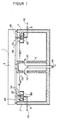
- FIG. 1 shows as part of a wastewater treatment plant a round basin 1 in vertical section as a media container, through which a liquid to be filtered flows.
- the direction of flow of the liquid is shown by Flow arrows 111 indicated.
- the circular pool 1 be formed in a conventional manner.
- the circular pool 1 has an outer wall 2 on the inside the two sides to the right and left of a flocculation room 80 surrounding filter drainage channel 20 is attached. Because of a system flowed through in free water levels 110 result in basin 1 including flocculation spaces 80 and the filter drainage channel 20 different water levels 110.
- Circle continuously rotating scraper bridge 3 which in can be manufactured in a conventional manner.
- a trained according to the invention that is attached to his cleaning and musculoskeletal system.
- the clearing wagon can also have its own, from the clearing bridge have independent drive.
- a filter screen is located in the filter drainage channel 20 (not shown in FIG. 1), through which the in Filter channel 20 overflowing liquid to be filtered flows.
- the filtered liquid flows from the bottom of the gutter 20 discharged via a derivative 5.
- the inlet side of the Filtered particles can be filtered through pipelines over the central structure 4 or on the outer wall 2 of the Basin 1 installed cradles (not shown in FIG. 1 shown) and are thus used for their own purposes become.
- FIG. 2 is an advantageous embodiment for construction and Operation of a filter drainage channel designed according to the invention 20 with a flocculation chamber arranged on one side 80 (felling area) shows in box gutter shape.
- Drainage channel 20 and the flute of the flocculation space 80 can be made of various Materials made and shaped. With the shown Embodiment they are from a console 21st worn, which is anchored to the outer wall 2 of the basin 1 is.
- the flocculation space 80 is directly on the inner walls 22 the filter drainage channel 20 with its own channel walls and floor attached or firmly connected to it, e.g. by welding.
- the flocculation space 80 can be entered by means of an input device 83 a flocculant can be entered.
- the flocculant is distributed in the direction of flow 111 by a mixing device 84, e.g. Baffles or agitators, evenly into the medium to be flocculated. That through the flocculant Enriched medium leaves 111 in the flow direction Flocculation space 80 and strikes in the direction of flow the top of the filter screen (60 in FIG. 5) in the Filter drainage channel 20.
- the liquid to be filtered flows through the strainer and collects from the filterable Fabrics separated at the bottom 25 of the gutter 20 and can forwarded to its determination via the derivative 5 become.
- FIG. 2 another device 50 for removal or picking up that accumulating on the top of the sieve Filter material that has a discharge line 51 a filter bulk container or trough 52 can be supplied.
- the cradle 50 and the derivative 51 move together with the scraper bridge 3 and the scraper carriage 40, and there are related in FIG. 2 fasteners shown provided with the suspension or the scraper bridge 3.
- the trough 52 can be on the inside of the outer wall 2 the pelvis 1 be attached.
- FIG. 3 shows a preferred embodiment of the scraper 40 and its support 23 and the sieve 60 in the vertical Cut and across (horizontal) to gutter 20.
- each on one right and left horizontal supports 23 and run through a guide rod 41 are connected to each other also serves as a hanger on the scraper bridge 3.
- the Supports 23 are fastened to the walls 22 of the gutter 20, welded on, for example, and with the screen mesh 61 supporting webs connected to each other.
- the clearing wagon 40 as already mentioned, by the sequence of movements the scraper bridge 3 with respect to the screen 60 and the drainage channel 20 moves.
- the clearing carriage 40 has its own drive (not shown).
- One on the guide rod 41 attached roller system consists of an upper roller bearing 44 and a lower roller bearing 45.
- the lower roller bearing 45 lies on the support edge 23 and carries at the same time the upper roller bearing 44 over which the filter screen 60 is raised and lowered.
- the roller bearings themselves are connected with cross and longitudinal struts.
- the filter screen 60 consists of a screen fabric 61 and two holding pads on which the screen mesh 61 in the shown Way is attached.
- the mesh material of the screen mesh 61 depends on the desired degree of filtering permeable.
- the filter screen spans across the Drainage channel 20 from one support edge 23 to the other support edge 23, on which the holding pads 62 in the filter position (FIG. 5).
- FIG. 3 shows the filter fabric 61 and the holding pads 62 lying in the raised state on the upper roller bearing 44.
- On the bottom of each holding pad 62 is advantageously a groove 63 is provided, which is in the Lowering the filter screen 60 into one on each support edge 23 upright spring 24 inserted.
- the holding pads 62 are preferably made of hard rubber and can for better Flexibility have a plastic mesh core.
- the holding pads can be shaped differently and differently be connected.
- the holding pads can also together with the sieve fabric form an endless belt, which in the drainage channel of round pools runs.
- a device for flushing can also be installed on the scraper and / or blow out for those on top of the Siebes filtered substances are provided.
- To this Purpose can advantageously be the guide linkage 41st train as a supply line, in the air and / or water Rinse the screen mesh 61 from below via outlet nozzles 46 and / or blow free.
- Filter material receiving device 50 also on the guide rod 41 forms the entire clearing device a unit rigidly connected to itself that only via the guide rod 41 with your own or someone else's Drive unit is connected and by this in relation to the stationary sieve can be moved in the trough.
- sealing washer 70 is between installed the roller bearings in the manner shown that the space between the holding pads 63 and the support edge 23 against lateral inflow of unfiltered Liquid in the gutter 20 below the Siebes 60 prevented.
- the sealing disk 70 is preferably designed so that it has a spring 71 runs in the groove 63 of the holding pad 62 and thereby the sealing properties of the spring 24 of the support 23 during of the sieve lifting process.
- FIG. 4 shows the scraper carriage 40 with the filter receiving device 50 and the filter screen 60 in longitudinal section to the filter drainage channel 20.
- the filter material receiving device 50 preferably has a collecting housing 53 in a spiral shape. Which is shown in the Favored inward tapering spiral shape the flow path of the rinsed from the screen fabric 61 and / or blown filter material into a gutter 54 at the end the spiral. This can be done in the gutter 54 Filter material via the discharge line 51 into the filter material collecting container or trough 52 (FIG. 1) transported or sucked or be pumped. On the filter material receiving device 50 can support accessories such as brushes, sliders, etc. of the clearing process. Like it out FIG. 4 can be seen, the Filter sieve 60 connected to the holding pads 62 Sieve mesh 61 from its filter layer on supports 23, of the moving scraper 40 in succession and continuously raised above the inflow water level 112.
- the sieve becomes 60 supported by the upper roller bearings 44.
- the screen mesh 61 hangs freely and can therefore advantageously from those arranged under the screen mesh 61 Nozzles 46 are blown free of the filter material and / or be washed free.
- the space between the Underside of the holding pads 62 and the support edge 23 arises and wedge-shaped at the beginning and end of the clearing carriage 40 is added by the between the roller supports arranged sealing washer 70 against lateral inflow sealed by unfiltered liquid.
- FIG. 5 shows the filter screen 60 in cross section Screen fabric 61 and holding pad 62 in the filter position lying on the support edge 23.
- the entire filter screen 60 through the from above over the upper edge of the filter drain channel wall liquid flowing down to a certain water level 112 overflowed.
- This water level presses the liquid to be filtered through the mesh 61, and the liquid flows on the underside of the mesh 61 separated from the sieve and filterable substances as pure water via the drain channel bottom 25 and Lead 5 from.
- the spring 24 standing upright on the support edge 23 is advantageously horizontally adjustable to the Sieve mesh 61 from one to the other support edge if necessary to be able to tension.
- the tension on the mesh 61 is on the groove 63, which is on the spring 24 on the Support 23 slips into the holding pad 62 on which the Sieve mesh 61 is attached, transferred.
- the interlocking of the groove 63 and the tongue 24 with appropriate training acts as a seal between the support edge 23 and the bottom 25 of the gutter, so that only filtered liquid reaches the bottom 25.
- connection between the screen mesh 61 and the Holding pad 62 is advantageously in the form of a Clamp connection with a formed in the holding pad 62 Clamping gap 64, into which the screen mesh 61 is inserted and the is firmly pressed together by means of a screw 65. On in this way, the screen mesh 61 becomes firm in position held between the holding pads 62.
- FIG. 6 shows a vertically arranged clearing device according to the invention during the cleaning process.
- FIG. 6 are some parts with the same reference numerals as in FIG. 1 to 5 provided. These parts have the same or one similar structure or an identical or similar function as in the previous figures, so that on the previous related description can be referenced.
- the following explanation and description deals with hence essentially with the differences between the especially in FIG. 2 and 3 illustrated horizontal version and the one shown in FIG. 6 shown vertical version the invention.
- the vertical arrangement of the supports or support edges 23 in the way shown vertically one above the other on the drainage channel 20 attached.
- the upper and lower support edge 23 by stiffening webs (not shown) with each other be connected, which also support the screen fabric.
- the screen mesh 61 of the vertical in the gutter 20 Filter screen 60 is clamped in the holding pad 62, the however, in contrast to the horizontal version in the here considered vertical version with the support edges 23 are firmly connected.
- the liquid to be filtered flows through the filter screen 60 in the direction of flow 111 from above (inlet side) down (drain side) and runs on the channel floor 25 into the derivation 5.
- the clearing wagon 40 is on the two vertical Support edges 23 hung, preferably on the holding pads 62, which are preferably in the longitudinal direction of the screen 60 extend over its entire length.
- the Clearing carriage 40 covers seen in the longitudinal direction of the sieve 60, just a short, straight section to be cleaned from and can from theticianr Hampshire 3 (FIG. 2) or your own Drive along the holding pads 62 or the support edges 23 are moved.
- the filter material receiving device 50 for removal and Picking up the filter material is fixed with the scraper 40 connected and runs on the top or inlet side of the Filter sieve 60 or the mesh 61 along and takes the filter material retained by the filter screen 60.
- the Filter material is through a preferably box-shaped collecting housing 53 caught in a gutter 54 am Bottom of the collecting housing 53 collected and via the derivative 51 transported in a collecting container.
- the cleaning the filter screen 60 is supported by the spray nozzles 46, the air and / or water through the mesh 61 Blow or spray from the bottom or drain side, in a manner similar to that in connection with FIG. 3rd has been described.
- the spray nozzles 46 are alike like the scraper 40 attached to the guide rod 41 and therefore move together with the collecting case 53 and the receiving device 50 in the longitudinal direction of the fixed Filter screen 60.
- the vertical arrangement described here to cleaning sieve section during the cleaning process not lifted out of the liquid.
- the construction of the researchersrwagens 40 and the receiving device 50 is rather so that the 60 migrating interior of the housing 62 possible from the liquid to be filtered is blocked.
- This shut off can by means of a sealing device 75 from groove and Spring for the area of the holding pads 62 and not shown sealing rollers in the area of the screen 61 reached become.
- the sealing device 75 and the sealing rollers can on the receiving device 50 or the collecting housing 53 be attached.
- the invention is preferably used in the Drainage channel of a sewage treatment plant, especially in the drainage channel a secondary clarifier.
- the gutter together with an adjacent flocculation room a unit form.
- Another area of application of the invention is, for example the separation of sediments and material in different Production, for example in food production and in the chemical industry.
Landscapes
- Chemical & Material Sciences (AREA)
- Chemical Kinetics & Catalysis (AREA)
- Filtration Of Liquid (AREA)
- Separation Using Semi-Permeable Membranes (AREA)
Description
In einem am 23. Februar 1995 eingetragenen deutschen Gebrauchsmuster U-93 16 495 ist ein Absetzbecken für eine Abwasseranlage beschrieben. Der Rand des Beckens dient als Überlauf zum Abziehen von geklärtem Wasser aus dem Becken. Auf dem Beckenrand ist entlang des
Claims (11)
- Verfahren zum kontinuierlichen Entfernen von abfilterbaren Stoffen aus einer in einem Behälter geklärten Flüssigkeit, bei dem manmittels einer Ablaufrinne (20) geklärte Flüssigkeit aus dem Behälter (2) durch Überlauf in die Ablaufrinne (20) abzieht,die abgezogene Flüssigkeit von der Oberseite bzw. Zulaufseite her durch ein ausschließlich innerhalb der Ablaufrinne (20) angeordnetes, langgestrecktes Sieb (60) fließen läßt,die durch das Sieb (60) geflossene gefilterte Flüssigkeit auf der Unterseite bzw. Ablaufseite des Siebes aus der Ablaufrinne (20) abführt, unddie abgefilterten Stoffe von der Oberseite bzw. Zulaufseite in Längsrichtung des Siebes (60) aufeinanderfolgender Siebabschnitte entfernt.
- Verfahren nach Anspruch 1, bei dem man einen in Längsrichtung des im übrigen ruhenden Siebes (60) wandernden Siebabschnitt über den Flüssigkeitsspiegel (112) in der Ablaufrinne (20) anhebt, die abgefilterten Stoffe von der Oberseite des jeweils über den Flüssigkeitsspiegel (112) angehobenen Siebabschnitts entfernt, und nach Möglichkeit die beim Anheben des Siebabschnitts gegebenenfalls auftretende Siebumgehung in einem abgedeckten Zustand hält, so daß im wesentlichen keine ungefilterte Flüssigkeit von der Oberseite bzw. Zulaufseite des Siebes (60) zu dessen Unterseite bzw. Ablaufseite gelangen kann.
- Verfahren nach Anspruch 1, bei dem man die aufeinanderfolgend zu reinigenden Siebabschnitte auf der Oberseite bzw. Zulaufseite des Siebes (60) derart abschirmt, daß möglichst wenig ungefilterte Flüssigkeit in einen in Längsrichtung des Siebes (60) wandernden Raum gelangt, der zum Auffangen der vom Sieb abgefilterten Stoffe dient.
- Verfahren nach einem der vorangegangenen Ansprüche, bei dem das Entfernen der abgefilterten Stoffe von der Oberseite bzw. Zulaufseite des Siebabschnitts durch Freispülen und/oder Freiblasen von der Unterseite bzw. Ablaufseite des Siebabschnitts her unterstützt wird.
- Verfahren nach einem der vorangegangenen Ansprüche, bei dem das Entfernen der abgefilterten Stoffe durch Absaugen auf der Oberseite bzw. Zulaufseite des Siebabschnitts vorgenommen wird.
- Anordnung zum kontinuierlichen Entfernen von abfilterbaren Stoffen aus einer in einem Behälter geklärten Flüssigkeit, enthaltend:eine Ablaufrinne (20) zum Abziehen geklärter Flüssigkeit aus dem Behälter (2)durch Überlauf in die Ablaufrinne (20) ,ein ausschließlich innerhalb der Ablaufrinne (20) angeordnetes Sieb (60), das sich in Längsrichtung der Ablaufrinne (20) erstreckt und die Ablaufrinne in einen auf der Oberseite bzw. Zulaufseite des Siebes gelegenen Aufnahmeraum für die zu filternde Flüssigkeit und einen auf der Unterseite bzw. Ablaufseite des Siebes gelegenen Ablaufraum für die gefilterte Flüssigkeit unterteilt, undeine in Längsrichtung der Ablaufrinne und des Siebes bewegbare Vorrichtung (50) zum Entfernen der abgefilterten Stoffe von der Oberseite bzw. Zulaufseite des innerhalb der Ablaufrinne (20) angeordneten Siebes (60).
- Anordnung nach Anspruch 6, enthaltend eine zusammen mit der Entfernungsvorrichtung (50) längs der Ablaufrinne (20) und des Siebes (60) bewegbare Vorrichtung (40) zum Anheben eines Abschnitts des Siebes (60) zwecks Entfernung der auf der Oberseite des jeweils angehobenen Siebabschnitts abgefilterten Stoffe mittels der Entfernungsvorrichtung (50), und eine von der Anhebevorrichtung (40) mitgeführte Abdeckung (70), die die beim Anheben des jeweiligen Siebabschnitts entstehende Umgehung abdeckt, so daß im wesentlichen keine gefilterte Flüssigkeit vom Aufnahmeraum in den Ablaufraum der Ablaufrinne (20) gelangen kann.
- Anordnung nach Anspruch 6, bei der das Sieb (60) im wesentlichen vertikal stehend in der Ablaufrinne (20) angeordnet ist.
- Anordnung nach einem der Ansprüche 6 bis 8, enthaltend eine mit der Entfernungsvorrichtung (50) in der Längsrichtung der Ablaufrinne (20) und des Siebes (60) bewegbare, auf der Unterseite bzw. Ablaufseite des jeweils zu reinigenden Siebabschnitts vorgesehene Freispül- und /oder Freiblasvorrichtung (46) zum Ablösen der auf der Oberseite bzw. Zulaufseite des Siebes (60) abgefilterten Stoffe.
- Anordnung nach einem der Ansprüche 6 bis 9, bei der die Entfernungsvorrichtung (50) eine Absaugvorrichtung enthält.
- Anordnung nach einem der Ansprüche 6 bis 10, bei der die bewegbare Vorrichtung (50) mit dem sich hin- und herbewegenden oder umlaufenden Räumer (3) einer Kläranlage verbunden ist.
Applications Claiming Priority (2)
| Application Number | Priority Date | Filing Date | Title |
|---|---|---|---|
| DE4427432 | 1994-08-03 | ||
| DE4427432A DE4427432A1 (de) | 1994-08-03 | 1994-08-03 | Verfahren und Anordnung zum kontinuierlichen Entfernen von abfilterbaren Stoffen aus einer Flüssigkeit |
Publications (2)
| Publication Number | Publication Date |
|---|---|
| EP0695571A1 EP0695571A1 (de) | 1996-02-07 |
| EP0695571B1 true EP0695571B1 (de) | 2001-11-14 |
Family
ID=6524806
Family Applications (1)
| Application Number | Title | Priority Date | Filing Date |
|---|---|---|---|
| EP95112180A Expired - Lifetime EP0695571B1 (de) | 1994-08-03 | 1995-08-03 | Verfahren und Anordnung zum kontinuierlichen Entfernen von abfilterbaren Stoffen aus einer Flüssigkeit |
Country Status (3)
| Country | Link |
|---|---|
| EP (1) | EP0695571B1 (de) |
| AT (1) | ATE208651T1 (de) |
| DE (2) | DE4427432A1 (de) |
Family Cites Families (19)
| Publication number | Priority date | Publication date | Assignee | Title |
|---|---|---|---|---|
| US2391697A (en) * | 1943-05-26 | 1945-12-25 | Infilco Inc | Liquid treating apparatus and process |
| US2814388A (en) * | 1957-03-18 | 1957-11-26 | Stamicarbon | Screening device |
| CA1022857A (en) * | 1972-06-22 | 1977-12-20 | Hydrocyclonics Corporation | Rotary screen filter with continuous cleaning |
| SE367849B (de) * | 1972-10-25 | 1974-06-10 | Celleco Ab | |
| DE2513972C3 (de) * | 1975-03-29 | 1979-10-04 | Erhard Rompf Apparatebau, 6349 Roth | Vorrichtung zur Entnahme von Schwimmstoffen aus einem Behälter zur Reinigung von Abwasser |
| US4203836A (en) * | 1977-06-25 | 1980-05-20 | Carter Tommie B | Method and apparatus for removing precipitated suspended solids from an effluent |
| HU184673B (en) * | 1979-03-21 | 1984-09-28 | Richter Gedeon Vegyeszet | Method and apparatus for yielding the solid material from fluids e.g. colloidlike solutions, sludges and suspensions containing protein and grease the solid content of which may be granulated by heat effect and/or the moisture content of solid content of which may be decreased by heat effect |
| DE8024225U1 (de) * | 1980-09-11 | 1980-12-18 | Haiges, Helmut, 7124 Boennigheim | Feststoff-abscheider fuer entwaesserungsanlagen |
| DE3124738A1 (de) * | 1981-06-24 | 1983-01-13 | Ralf F. Piepho, Abwassertechnik GmbH, 3015 Wennigsen | Transportable vorrichtung zum aufbereiten von verbrauchten emulsionen, loesungen und industrieabwaessern oder dergleichen |
| US4377485A (en) * | 1981-09-15 | 1983-03-22 | Lenox Institute For Research, Inc. | Apparatus and method for clarification of water using combined flotation and filtration processes |
| EP0191194A1 (de) * | 1985-02-15 | 1986-08-20 | Gist-Brocades N.V. | Vorrichtung und Verfahren zum Abscheiden von Feststoffteilchen aus einer Suspension und zum Reinigen oder Auslaugen dieser Teilchen |
| GB8524495D0 (en) * | 1985-10-04 | 1985-11-06 | Ontario Research Foundation | Buoyant media filter |
| DE8601129U1 (de) * | 1986-01-18 | 1986-04-03 | Hydropress Wallander & Co. AB, Mölndal | Vorrichtung zur Trennung von Feststoffen aus Flüssigkeiten |
| DE3635178A1 (de) * | 1986-10-16 | 1988-04-21 | Hans J Altmeyer | Vorrichtung zum entwaessern einer suspension, insbesondere eines klaerschlammes |
| DE4001921A1 (de) * | 1990-01-24 | 1991-07-25 | Buderus Bau & Abwassertechnik | Leichtfluessigkeitsabscheider |
| CH681063A5 (en) * | 1990-05-17 | 1993-01-15 | Heinz Wartenweiler | Cleaner for sewage from multi-chamber cesspit - comprises container including dwell zone and filter and out-flow zones to give clean water without using chemicals |
| DE9104763U1 (de) * | 1990-06-05 | 1991-06-27 | Mannesmann AG, 4000 Düsseldorf | Vorrichtung zum Reinigen von Kreislaufflüssigkeiten |
| US5221469A (en) * | 1991-12-09 | 1993-06-22 | Hydroflow, Inc. | Filtration system |
| DE9316495U1 (de) | 1993-10-28 | 1995-02-23 | Altmann, Peter, 47929 Grefrath | Absetzbecken für eine Abwasseranlage |
-
1994
- 1994-08-03 DE DE4427432A patent/DE4427432A1/de not_active Withdrawn
-
1995
- 1995-08-03 AT AT95112180T patent/ATE208651T1/de not_active IP Right Cessation
- 1995-08-03 EP EP95112180A patent/EP0695571B1/de not_active Expired - Lifetime
- 1995-08-03 DE DE59509822T patent/DE59509822D1/de not_active Expired - Fee Related
Also Published As
| Publication number | Publication date |
|---|---|
| DE59509822D1 (de) | 2001-12-20 |
| ATE208651T1 (de) | 2001-11-15 |
| DE4427432A1 (de) | 1996-02-08 |
| EP0695571A1 (de) | 1996-02-07 |
Similar Documents
| Publication | Publication Date | Title |
|---|---|---|
| DE69104605T2 (de) | Gerät zum filtrieren von flüssigkeiten. | |
| DE69205198T2 (de) | Vorrichtung zur Behandlung von Belebtschlamm. | |
| EP0074966A1 (de) | Filtervorrichtung zur trennung von flüssigkeiten und feststoffen. | |
| DE2743963A1 (de) | Vorrichtung zum reinigen von verschmutztem wasser | |
| EP0530672B1 (de) | Auswaschbarer Filter | |
| DE3902829A1 (de) | Rueckspuelbarer filter | |
| DE2146838B2 (de) | Verfahren und Vorrichtung zum Filtrieren von Flüssigkeiten | |
| DE2644877C3 (de) | Verfahren und Vorrichtung zur Trennung von Feststoffen aus Flüssigkeitssuspensionen | |
| EP0695571B1 (de) | Verfahren und Anordnung zum kontinuierlichen Entfernen von abfilterbaren Stoffen aus einer Flüssigkeit | |
| EP0265385B1 (de) | Vorrichtung zur Reinigung eines Siebes oder Rechens in einer Abwasseranlage | |
| EP0622099B1 (de) | Trenn- und Filtriervorrichtung zur Fest/Flüssigtrennung, insbesondere mit Trockenhilfe | |
| DE2005052B2 (de) | Vorrichtung zum Abfuhren von Abwasser aus einem Belüftungsbecken | |
| DE1812478C3 (de) | Vorrichtung zur Schwimmschlamm raumung in einem Klarbecken | |
| DE1536826B2 (de) | Filtervorrichtung | |
| EP1760046B1 (de) | Kompaktes Wasserreinigungsgerät für Teiche | |
| DE69112418T2 (de) | Abwasserfiltration. | |
| EP0305606B1 (de) | Rückspülbare Filteranlage | |
| DE3004961A1 (de) | Siebkorb mit innenliegendem siebgewebe zum einsatz in siebbaendern, siebtrommeln oder gleichartigen konstruktionen | |
| DE1813635C3 (de) | Vorrichtung zur biologischen Reinigung von Abwasser nach dem Be lebung s verfahren | |
| EP0495403A1 (de) | Vorrichtung zum Reinigen von Abwasser | |
| EP1441829B1 (de) | Vorrichtung und verfahren zur reinigung von abwasser | |
| DE102005042457B4 (de) | Wasserreinigungsgerät für Teiche oder dergleichen Gewässer | |
| DE3905832C2 (de) | ||
| DE9300954U1 (de) | Filtervorrichtung für Flüssigkeiten | |
| DE2242613A1 (de) | Vorrichtung zum reinigen von verschmutztem wasser |
Legal Events
| Date | Code | Title | Description |
|---|---|---|---|
| PUAI | Public reference made under article 153(3) epc to a published international application that has entered the european phase |
Free format text: ORIGINAL CODE: 0009012 |
|
| AK | Designated contracting states |
Kind code of ref document: A1 Designated state(s): AT CH DE ES FR GB GR IT LI NL |
|
| 17P | Request for examination filed |
Effective date: 19960306 |
|
| 17Q | First examination report despatched |
Effective date: 19990430 |
|
| GRAG | Despatch of communication of intention to grant |
Free format text: ORIGINAL CODE: EPIDOS AGRA |
|
| GRAG | Despatch of communication of intention to grant |
Free format text: ORIGINAL CODE: EPIDOS AGRA |
|
| GRAH | Despatch of communication of intention to grant a patent |
Free format text: ORIGINAL CODE: EPIDOS IGRA |
|
| GRAG | Despatch of communication of intention to grant |
Free format text: ORIGINAL CODE: EPIDOS AGRA |
|
| GRAH | Despatch of communication of intention to grant a patent |
Free format text: ORIGINAL CODE: EPIDOS IGRA |
|
| GRAH | Despatch of communication of intention to grant a patent |
Free format text: ORIGINAL CODE: EPIDOS IGRA |
|
| GRAA | (expected) grant |
Free format text: ORIGINAL CODE: 0009210 |
|
| AK | Designated contracting states |
Kind code of ref document: B1 Designated state(s): AT CH DE ES FR GB GR IT LI NL |
|
| PG25 | Lapsed in a contracting state [announced via postgrant information from national office to epo] |
Ref country code: NL Free format text: LAPSE BECAUSE OF FAILURE TO SUBMIT A TRANSLATION OF THE DESCRIPTION OR TO PAY THE FEE WITHIN THE PRESCRIBED TIME-LIMIT Effective date: 20011114 Ref country code: IT Free format text: LAPSE BECAUSE OF FAILURE TO SUBMIT A TRANSLATION OF THE DESCRIPTION OR TO PAY THE FEE WITHIN THE PRE;WARNING: LAPSES OF ITALIAN PATENTS WITH EFFECTIVE DATE BEFORE 2007 MAY HAVE OCCURRED AT ANY TIME BEFORE 2007. THE CORRECT EFFECTIVE DATE MAY BE DIFFERENT FROM THE ONE RECORDED.SCRIBED TIME-LIMIT Effective date: 20011114 Ref country code: GR Free format text: LAPSE BECAUSE OF FAILURE TO SUBMIT A TRANSLATION OF THE DESCRIPTION OR TO PAY THE FEE WITHIN THE PRESCRIBED TIME-LIMIT Effective date: 20011114 Ref country code: GB Free format text: LAPSE BECAUSE OF FAILURE TO SUBMIT A TRANSLATION OF THE DESCRIPTION OR TO PAY THE FEE WITHIN THE PRESCRIBED TIME-LIMIT Effective date: 20011114 Ref country code: FR Free format text: LAPSE BECAUSE OF FAILURE TO SUBMIT A TRANSLATION OF THE DESCRIPTION OR TO PAY THE FEE WITHIN THE PRESCRIBED TIME-LIMIT Effective date: 20011114 |
|
| REF | Corresponds to: |
Ref document number: 208651 Country of ref document: AT Date of ref document: 20011115 Kind code of ref document: T |
|
| REG | Reference to a national code |
Ref country code: CH Ref legal event code: EP |
|
| REF | Corresponds to: |
Ref document number: 59509822 Country of ref document: DE Date of ref document: 20011220 |
|
| REG | Reference to a national code |
Ref country code: GB Ref legal event code: IF02 |
|
| NLV1 | Nl: lapsed or annulled due to failure to fulfill the requirements of art. 29p and 29m of the patents act | ||
| GBV | Gb: ep patent (uk) treated as always having been void in accordance with gb section 77(7)/1977 [no translation filed] |
Effective date: 20011114 |
|
| PG25 | Lapsed in a contracting state [announced via postgrant information from national office to epo] |
Ref country code: ES Free format text: LAPSE BECAUSE OF FAILURE TO SUBMIT A TRANSLATION OF THE DESCRIPTION OR TO PAY THE FEE WITHIN THE PRESCRIBED TIME-LIMIT Effective date: 20020530 |
|
| PG25 | Lapsed in a contracting state [announced via postgrant information from national office to epo] |
Ref country code: AT Free format text: LAPSE BECAUSE OF NON-PAYMENT OF DUE FEES Effective date: 20020803 |
|
| PG25 | Lapsed in a contracting state [announced via postgrant information from national office to epo] |
Ref country code: LI Free format text: LAPSE BECAUSE OF NON-PAYMENT OF DUE FEES Effective date: 20020831 Ref country code: CH Free format text: LAPSE BECAUSE OF NON-PAYMENT OF DUE FEES Effective date: 20020831 |
|
| PLBE | No opposition filed within time limit |
Free format text: ORIGINAL CODE: 0009261 |
|
| STAA | Information on the status of an ep patent application or granted ep patent |
Free format text: STATUS: NO OPPOSITION FILED WITHIN TIME LIMIT |
|
| EN | Fr: translation not filed | ||
| 26N | No opposition filed | ||
| REG | Reference to a national code |
Ref country code: CH Ref legal event code: PL |
|
| PGFP | Annual fee paid to national office [announced via postgrant information from national office to epo] |
Ref country code: DE Payment date: 20090226 Year of fee payment: 14 |
|
| PG25 | Lapsed in a contracting state [announced via postgrant information from national office to epo] |
Ref country code: DE Free format text: LAPSE BECAUSE OF NON-PAYMENT OF DUE FEES Effective date: 20100302 |