EP0695603A1 - Dispositif de serrage à genouillère - Google Patents
Dispositif de serrage à genouillère Download PDFInfo
- Publication number
- EP0695603A1 EP0695603A1 EP95112131A EP95112131A EP0695603A1 EP 0695603 A1 EP0695603 A1 EP 0695603A1 EP 95112131 A EP95112131 A EP 95112131A EP 95112131 A EP95112131 A EP 95112131A EP 0695603 A1 EP0695603 A1 EP 0695603A1
- Authority
- EP
- European Patent Office
- Prior art keywords
- shells
- head piece
- toggle lever
- rollers
- guideways
- Prior art date
- Legal status (The legal status is an assumption and is not a legal conclusion. Google has not performed a legal analysis and makes no representation as to the accuracy of the status listed.)
- Granted
Links
Images


Classifications
-
- B—PERFORMING OPERATIONS; TRANSPORTING
- B25—HAND TOOLS; PORTABLE POWER-DRIVEN TOOLS; MANIPULATORS
- B25B—TOOLS OR BENCH DEVICES NOT OTHERWISE PROVIDED FOR, FOR FASTENING, CONNECTING, DISENGAGING, OR HOLDING
- B25B5/00—Clamps
- B25B5/16—Details, e.g. jaws, jaw attachments
-
- B—PERFORMING OPERATIONS; TRANSPORTING
- B25—HAND TOOLS; PORTABLE POWER-DRIVEN TOOLS; MANIPULATORS
- B25B—TOOLS OR BENCH DEVICES NOT OTHERWISE PROVIDED FOR, FOR FASTENING, CONNECTING, DISENGAGING, OR HOLDING
- B25B5/00—Clamps
- B25B5/06—Arrangements for positively actuating jaws
- B25B5/12—Arrangements for positively actuating jaws using toggle links
- B25B5/122—Arrangements for positively actuating jaws using toggle links with fluid drive
Definitions
- the invention relates to a toggle lever clamping device for clamping workpieces, consisting of a drive member with an actuating rod whose end provided with a roller pin engages with rollers in guide slots of a headpiece placed on the drive member and is articulated via an intermediate member to a tensioning lever mounted on the headpiece.
- toggle lever clamping devices are known, for example, from US-A-521 295 and GB-A-12 81 598.
- the guide slots worked into the side flanks of the head piece are highly stressed parts that have to be hardened accordingly. In the event of wear, either the entire head piece must be replaced or, if this should be made in two parts, the side parts must be replaced.
- the guide slots must be covered with sealing plates on the side to prevent the guide rollers and the guideways from becoming dirty.
- the invention has for its object to improve a toggle lever tensioning device of the generic type in such a way that with a simplified overall construction and with wear of the guideways, the head piece is not directly affected and the hardening measures themselves are not to be carried out on it, and in the event of guideway wear this occurs
- Guideways are accessible for easy interchangeability and this is combined with the requirement that at the same time create an area that is easily accessible from the outside and is suitable for accommodating end position sensors, should such sensors be desired and required.
- the previous guide slots thus lose their guiding and supporting function, i.e., in the end, they are only pass-through slots for the roller support pin, which is connected to the end of the piston rod. Accordingly, no hardening of the headpiece material is to be carried out on the headpiece itself in the production of these penetration slots.
- the shells to be fitted on the headpiece flanks are also used to hold the roller support pin in its central position with respect to the end of the piston rod.
- the roller trunnion and ultimately also the rollers therefore no longer need to be fixed, i.e.
- roller support spigot is fixed against transverse displacement to the piston rod axis by the fitted shells, and the rollers also no longer need to be fixed on the roller support spigot, which was previously relatively complex with snap rings, since this was between the flank surfaces of the head piece on the one hand and the inner walls of the two outer shells on the other hand. In this respect, any role exchange that may become necessary is also considerably simplified.
- these side-by-side shells have the following advantages: No hardening measures are to be taken on the head piece itself, and the guide slots that are otherwise to be made to the exact size on the head piece are merely to be designed as penetration slots.
- the shells are separate parts and can be prefabricated independently of the head piece.
- the shells have a triple function, namely guiding the rollers, locking the roller support pin against transverse misalignment and accommodating end position sensors if these have to be provided. Since all of these functions, which otherwise have to be taken into account on the head piece, are relocated to the shells, assembly, disassembly and thus interchangeability of the parts subject to wear are considerably simplified.
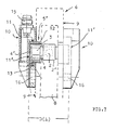
- the toggle lever tensioning device consists of a drive member 1 (for example pneumatic cylinder) with an actuating rod 2, whose end 4 ′ provided with a roller support pin 4 engages with rollers 3 in guide slots 5 of a head piece 6 placed on the drive member 1 and via an intermediate member 7 is pivotally connected to a tension lever 8 mounted on the head piece 6.
- a drive member 1 for example pneumatic cylinder
- actuating rod 2 whose end 4 ′ provided with a roller support pin 4 engages with rollers 3 in guide slots 5 of a head piece 6 placed on the drive member 1 and via an intermediate member 7 is pivotally connected to a tension lever 8 mounted on the head piece 6.
- FIGS. 5, 7, For this purpose, reference is made in particular to FIGS. 5, 7, from which the assignment of the roller support pin 4 with the rollers 3 to the hardened guideway and to the shells 10 arranged on the outer flanks 9 of the head piece 6 can be seen.
- the inner walls 11 'of the shells 10, which are adjacent to the ends 4' of the roller support pin 4, have a distance D from one another, which essentially corresponds to the length L of the roller support pin 4.
- the rollers 3 are seated on slightly reduced-diameter ends 4 'of the roller support pin. As a result, no additional elements are required to keep the roller support pin 4 central to the rod head piece 2 ', which also applies to the rollers 3 themselves. Assembly and disassembly are, as is easily conceivable, easy to carry out, i.e. the shells 10 are only screwed on or off.
- the hardened guideways 12 of the shells 10 are advantageously partially engaging with respect to their width B in the guiding slots 5 of the head piece 6 arranged, that is, the precise positioning of the shells 10 is ensured, and the mounting holes 16 may well have some play.
- the shells 10 are expediently formed from a suitable plastic, and in these the guideways 12 and metallic plates 13 forming the inner walls 11 'of the shells 10 are suitably firmly connected to the plastic.
- this tensioning device is comparatively simplified insofar as the shells 10, as can be seen in particular in FIG. 5, are also used to accommodate end position sensors 14, for which special designs on the head piece 6 are otherwise also required in order to if desired, to be able to install.
- One of the shells 10, in which the sensors are arranged with corresponding current conductors, serves at the same time as a carrier for a connector plug 15.
- both shells are designed identically for series production, with on the not used shell the relevant vacancies for receiving the sensors and the connector 15 simply remain vacant and open, which is particularly true for the sensor positions, since these are closed by attaching the relevant shell by the relevant flank wall 9 of the head piece 6. For the rest, of course, nothing stands in the way of closing the connection opening for the connector plug 15 with a plug.
- the penetration slots 5 are to be worked into the headpiece flanks so precisely that their flank surfaces serve as support surfaces for the engaging, hardened guideways 12.
Landscapes
- Engineering & Computer Science (AREA)
- Mechanical Engineering (AREA)
- Silver Salt Photography Or Processing Solution Therefor (AREA)
- Gripping Jigs, Holding Jigs, And Positioning Jigs (AREA)
- Press Drives And Press Lines (AREA)
- Jigs For Machine Tools (AREA)
- Moulds For Moulding Plastics Or The Like (AREA)
Applications Claiming Priority (2)
| Application Number | Priority Date | Filing Date | Title |
|---|---|---|---|
| DE9412722U DE9412722U1 (de) | 1994-08-06 | 1994-08-06 | Kniehebelspannvorrichtung |
| DE9412722U | 1994-08-06 |
Publications (2)
| Publication Number | Publication Date |
|---|---|
| EP0695603A1 true EP0695603A1 (fr) | 1996-02-07 |
| EP0695603B1 EP0695603B1 (fr) | 1997-10-29 |
Family
ID=6912103
Family Applications (1)
| Application Number | Title | Priority Date | Filing Date |
|---|---|---|---|
| EP95112131A Expired - Lifetime EP0695603B1 (fr) | 1994-08-06 | 1995-08-02 | Dispositif de serrage à genouillère |
Country Status (3)
| Country | Link |
|---|---|
| EP (1) | EP0695603B1 (fr) |
| DE (2) | DE9412722U1 (fr) |
| ES (1) | ES2109041T3 (fr) |
Cited By (4)
| Publication number | Priority date | Publication date | Assignee | Title |
|---|---|---|---|---|
| EP0803331A1 (fr) * | 1996-04-25 | 1997-10-29 | TÜNKERS MASCHINENBAU GmbH | Dispositif de serrage à genouillère pour la construction en carrosserie |
| FR2780324A1 (fr) * | 1998-06-26 | 1999-12-31 | Genus Technologies | Dispositif de positionnement, de maintien ou de serrage |
| US6189877B1 (en) | 1998-06-26 | 2001-02-20 | Genus Technologies | Device for positioning, holding or gripping |
| CN105313040A (zh) * | 2014-08-01 | 2016-02-10 | 佩佩尔+富克斯有限公司 | 用于肘形杆张紧装置的查问单元 |
Families Citing this family (2)
| Publication number | Priority date | Publication date | Assignee | Title |
|---|---|---|---|---|
| DE19757947A1 (de) * | 1997-12-27 | 1999-07-01 | Sta Co Mettallerzeugnisse Gmbh | Spannvorrichtung |
| CN111604838A (zh) * | 2020-06-08 | 2020-09-01 | 陈芳芳 | 一种仪器仪表辅助夹紧装置及其应用 |
Citations (6)
| Publication number | Priority date | Publication date | Assignee | Title |
|---|---|---|---|---|
| US521295A (en) | 1894-06-12 | And george sniffin | ||
| GB1281598A (en) | 1968-10-08 | 1972-07-12 | Dover Corp | Power operated work clamping device |
| FR2340798A1 (fr) * | 1976-02-13 | 1977-09-09 | Polymatic Sa | Tete de bridage irreversible a attelage flottant et demontage rapide |
| FR2540021A1 (fr) * | 1983-01-27 | 1984-08-03 | Franche Comte Alsace Etudes Te | Dispositif de serrage pneumatique a genouillere |
| DE4111430A1 (de) * | 1990-04-12 | 1991-10-17 | Volker Schlueter | Druckmittelbetaetigte spannvorrichtung |
| EP0530527A1 (fr) * | 1991-09-03 | 1993-03-10 | DE-STA-CO METALLERZEUGNISSE GmbH | Moyens de serrage |
Family Cites Families (11)
| Publication number | Priority date | Publication date | Assignee | Title |
|---|---|---|---|---|
| US894963A (en) | 1907-07-31 | 1908-08-04 | Nathaniel W Martin | Wrench. |
| US3618931A (en) * | 1970-01-19 | 1971-11-09 | Leland F Blatt | Cam wedge power clamp |
| US3938208A (en) * | 1974-08-15 | 1976-02-17 | Yuan Ho Lee | Knockout mechanism for a high-speed automatic cold heading machine |
| DE3022376C2 (de) * | 1980-06-14 | 1985-08-01 | De-Sta-Co Metallerzeugnisse Gmbh, 6000 Frankfurt | Kniehebelspannvorrichtung zum Festspannen von Werkstücken |
| DE3602738C1 (de) * | 1986-01-30 | 1987-07-09 | Sta Co Mettallerzeugnisse Gmbh | Spannvorrichtung |
| US4723767A (en) * | 1986-08-08 | 1988-02-09 | De-Sta-Co Division, Dover Resources, Inc. | Rotary powered linear actuated clamp |
| DE3638526C1 (de) * | 1986-11-11 | 1987-07-30 | Sta Co Mettallerzeugnisse Gmbh | Elektromotorisch antreibbare Werkstueckspannvorrichtung |
| FR2639569B1 (fr) * | 1988-11-25 | 1991-01-18 | Polymatic Sa | Tete de bridage a rattrapage de jeux |
| DE3938208C1 (fr) | 1989-11-17 | 1990-11-22 | Josef Gerhard 4030 Ratingen De Tuenkers | |
| DE4025530A1 (de) * | 1990-01-09 | 1991-07-11 | Sta Co Mettallerzeugnisse Gmbh | Spannvorrichtung |
| US5215295A (en) * | 1992-06-29 | 1993-06-01 | Delaware Capital Formation | Enclosed rotatable head power clamp |
-
1994
- 1994-08-06 DE DE9412722U patent/DE9412722U1/de not_active Expired - Lifetime
-
1995
- 1995-08-02 DE DE59500902T patent/DE59500902D1/de not_active Expired - Fee Related
- 1995-08-02 EP EP95112131A patent/EP0695603B1/fr not_active Expired - Lifetime
- 1995-08-02 ES ES95112131T patent/ES2109041T3/es not_active Expired - Lifetime
Patent Citations (6)
| Publication number | Priority date | Publication date | Assignee | Title |
|---|---|---|---|---|
| US521295A (en) | 1894-06-12 | And george sniffin | ||
| GB1281598A (en) | 1968-10-08 | 1972-07-12 | Dover Corp | Power operated work clamping device |
| FR2340798A1 (fr) * | 1976-02-13 | 1977-09-09 | Polymatic Sa | Tete de bridage irreversible a attelage flottant et demontage rapide |
| FR2540021A1 (fr) * | 1983-01-27 | 1984-08-03 | Franche Comte Alsace Etudes Te | Dispositif de serrage pneumatique a genouillere |
| DE4111430A1 (de) * | 1990-04-12 | 1991-10-17 | Volker Schlueter | Druckmittelbetaetigte spannvorrichtung |
| EP0530527A1 (fr) * | 1991-09-03 | 1993-03-10 | DE-STA-CO METALLERZEUGNISSE GmbH | Moyens de serrage |
Cited By (7)
| Publication number | Priority date | Publication date | Assignee | Title |
|---|---|---|---|---|
| EP0803331A1 (fr) * | 1996-04-25 | 1997-10-29 | TÜNKERS MASCHINENBAU GmbH | Dispositif de serrage à genouillère pour la construction en carrosserie |
| FR2780324A1 (fr) * | 1998-06-26 | 1999-12-31 | Genus Technologies | Dispositif de positionnement, de maintien ou de serrage |
| US6189877B1 (en) | 1998-06-26 | 2001-02-20 | Genus Technologies | Device for positioning, holding or gripping |
| EP0967050A3 (fr) * | 1998-06-26 | 2001-05-30 | Genus Technologies | Dispositif de positionnement, de maintien ou de serrage |
| CN105313040A (zh) * | 2014-08-01 | 2016-02-10 | 佩佩尔+富克斯有限公司 | 用于肘形杆张紧装置的查问单元 |
| CN105313040B (zh) * | 2014-08-01 | 2017-10-27 | 佩佩尔+富克斯有限公司 | 用于肘形杆张紧装置的查问单元 |
| US10710205B2 (en) | 2014-08-01 | 2020-07-14 | Pepperl+Fuchs Gmbh | Query unit for toggle lever clamp |
Also Published As
| Publication number | Publication date |
|---|---|
| DE59500902D1 (de) | 1997-12-04 |
| EP0695603B1 (fr) | 1997-10-29 |
| ES2109041T3 (es) | 1998-01-01 |
| DE9412722U1 (de) | 1994-09-29 |
Similar Documents
| Publication | Publication Date | Title |
|---|---|---|
| DE1632808C3 (de) | Gehäuse für Scheibenmäher | |
| DE69934751T2 (de) | Elektrische Betätigungsvorrichtung | |
| DE3235224C2 (fr) | ||
| EP0060498B1 (fr) | Appareil pour l'assemblage bout à bout de deux tiges de renforcement au moyen d'un manchon d'accouplement | |
| DE29517590U1 (de) | Kettenförderer mit verbesserten Gleiteigenschaften | |
| EP1075945A1 (fr) | Machine d'impression | |
| DE102007017485A1 (de) | Vorrichtung zum Trennen eines Stranges aus plastischem Material mit einem eine Kerbvorrichtung und eine Schneidevorrichtung tragenden Träger | |
| EP0643233B1 (fr) | Dispositif de guidage linéaire | |
| DE4334611C2 (de) | Linear-Gleitführung | |
| DE3408912C1 (de) | Energieführungskette | |
| EP0695603B1 (fr) | Dispositif de serrage à genouillère | |
| DE29604692U1 (de) | Vorrichtung zum Auslenken einer drehbeweglich angeordneten Baueinheit, insbesondere eines Fensters | |
| DE4111430A1 (de) | Druckmittelbetaetigte spannvorrichtung | |
| DE2605734C3 (de) | Spritzgießform mit Formbacken | |
| DE69913040T2 (de) | Antriebsvorrichtung für die Glieder einer Schubkette | |
| EP0436883B1 (fr) | Dispositif de serrage | |
| DE102010014044A1 (de) | Segment einer Sägekette für hochtourige Motorsägen zum Sägen von Gestein, Beton, Ziegel und Metall | |
| DE4409420A1 (de) | Betätigungsvorrichtung für Handhaben von Türen und Fenstern | |
| DE3706236C2 (de) | Verbindungselement für zwei Tragteile | |
| EP0232294A1 (fr) | Element d'articulation des deux extremites de la chenille d'un vehicule chenille. | |
| DE20005900U1 (de) | Anlage zum Herstellen und Kaschieren von Profilen | |
| DE2531976B2 (de) | Loesbare schwenkverbindung von nadelstaeben an beidseitig mit dem antrieb dienenden ketten fuer die nadelstaebe versehenen nadelstabstrecken | |
| DE19925559C1 (de) | Kette für Spannrahmentrockner | |
| DE2615238C2 (de) | Elektrische Grenztastschaltvorrichtung | |
| DE102017221109A1 (de) | Gießdüse |
Legal Events
| Date | Code | Title | Description |
|---|---|---|---|
| PUAI | Public reference made under article 153(3) epc to a published international application that has entered the european phase |
Free format text: ORIGINAL CODE: 0009012 |
|
| AK | Designated contracting states |
Kind code of ref document: A1 Designated state(s): DE ES FR GB IT SE |
|
| 17P | Request for examination filed |
Effective date: 19960726 |
|
| GRAG | Despatch of communication of intention to grant |
Free format text: ORIGINAL CODE: EPIDOS AGRA |
|
| GRAH | Despatch of communication of intention to grant a patent |
Free format text: ORIGINAL CODE: EPIDOS IGRA |
|
| 17Q | First examination report despatched |
Effective date: 19970317 |
|
| GRAH | Despatch of communication of intention to grant a patent |
Free format text: ORIGINAL CODE: EPIDOS IGRA |
|
| GRAA | (expected) grant |
Free format text: ORIGINAL CODE: 0009210 |
|
| AK | Designated contracting states |
Kind code of ref document: B1 Designated state(s): DE ES FR GB IT SE |
|
| ET | Fr: translation filed | ||
| REF | Corresponds to: |
Ref document number: 59500902 Country of ref document: DE Date of ref document: 19971204 |
|
| REG | Reference to a national code |
Ref country code: ES Ref legal event code: FG2A Ref document number: 2109041 Country of ref document: ES Kind code of ref document: T3 |
|
| ITF | It: translation for a ep patent filed | ||
| GBT | Gb: translation of ep patent filed (gb section 77(6)(a)/1977) |
Effective date: 19980202 |
|
| PLBE | No opposition filed within time limit |
Free format text: ORIGINAL CODE: 0009261 |
|
| STAA | Information on the status of an ep patent application or granted ep patent |
Free format text: STATUS: NO OPPOSITION FILED WITHIN TIME LIMIT |
|
| 26N | No opposition filed | ||
| PGFP | Annual fee paid to national office [announced via postgrant information from national office to epo] |
Ref country code: GB Payment date: 20000727 Year of fee payment: 6 |
|
| PGFP | Annual fee paid to national office [announced via postgrant information from national office to epo] |
Ref country code: SE Payment date: 20000808 Year of fee payment: 6 |
|
| PGFP | Annual fee paid to national office [announced via postgrant information from national office to epo] |
Ref country code: ES Payment date: 20000824 Year of fee payment: 6 |
|
| PGFP | Annual fee paid to national office [announced via postgrant information from national office to epo] |
Ref country code: FR Payment date: 20000829 Year of fee payment: 6 |
|
| PGFP | Annual fee paid to national office [announced via postgrant information from national office to epo] |
Ref country code: DE Payment date: 20000927 Year of fee payment: 6 |
|
| PG25 | Lapsed in a contracting state [announced via postgrant information from national office to epo] |
Ref country code: GB Free format text: LAPSE BECAUSE OF NON-PAYMENT OF DUE FEES Effective date: 20010802 |
|
| PG25 | Lapsed in a contracting state [announced via postgrant information from national office to epo] |
Ref country code: SE Free format text: LAPSE BECAUSE OF NON-PAYMENT OF DUE FEES Effective date: 20010803 Ref country code: ES Free format text: LAPSE BECAUSE OF NON-PAYMENT OF DUE FEES Effective date: 20010803 |
|
| GBPC | Gb: european patent ceased through non-payment of renewal fee |
Effective date: 20010802 |
|
| EUG | Se: european patent has lapsed |
Ref document number: 95112131.8 |
|
| PG25 | Lapsed in a contracting state [announced via postgrant information from national office to epo] |
Ref country code: FR Free format text: LAPSE BECAUSE OF NON-PAYMENT OF DUE FEES Effective date: 20020430 |
|
| PG25 | Lapsed in a contracting state [announced via postgrant information from national office to epo] |
Ref country code: DE Free format text: LAPSE BECAUSE OF NON-PAYMENT OF DUE FEES Effective date: 20020501 |
|
| REG | Reference to a national code |
Ref country code: FR Ref legal event code: ST |
|
| REG | Reference to a national code |
Ref country code: ES Ref legal event code: FD2A Effective date: 20020911 |
|
| PG25 | Lapsed in a contracting state [announced via postgrant information from national office to epo] |
Ref country code: IT Free format text: LAPSE BECAUSE OF NON-PAYMENT OF DUE FEES;WARNING: LAPSES OF ITALIAN PATENTS WITH EFFECTIVE DATE BEFORE 2007 MAY HAVE OCCURRED AT ANY TIME BEFORE 2007. THE CORRECT EFFECTIVE DATE MAY BE DIFFERENT FROM THE ONE RECORDED. Effective date: 20050802 |