EP0696252B1 - Satellit mit aerodynamischer steuereinrichtung - Google Patents
Satellit mit aerodynamischer steuereinrichtung Download PDFInfo
- Publication number
- EP0696252B1 EP0696252B1 EP94915182A EP94915182A EP0696252B1 EP 0696252 B1 EP0696252 B1 EP 0696252B1 EP 94915182 A EP94915182 A EP 94915182A EP 94915182 A EP94915182 A EP 94915182A EP 0696252 B1 EP0696252 B1 EP 0696252B1
- Authority
- EP
- European Patent Office
- Prior art keywords
- control surfaces
- artificial satellite
- satellite according
- satellite
- roll
- Prior art date
- Legal status (The legal status is an assumption and is not a legal conclusion. Google has not performed a legal analysis and makes no representation as to the accuracy of the status listed.)
- Expired - Lifetime
Links
Images




Classifications
-
- B—PERFORMING OPERATIONS; TRANSPORTING
- B64—AIRCRAFT; AVIATION; COSMONAUTICS
- B64G—COSMONAUTICS; VEHICLES OR EQUIPMENT THEREFOR
- B64G1/00—Cosmonautic vehicles
- B64G1/22—Parts of, or equipment specially adapted for fitting in or to, cosmonautic vehicles
- B64G1/24—Guiding or controlling apparatus, e.g. for attitude control
- B64G1/244—Spacecraft control systems
Definitions
- the subject of the invention is an artificial satellite provided with aerodynamic control surfaces for controlling the orientation of this satellite.
- the traditional means for orienting the satellites consist of wheels using the gyroscopic effect or the reaction and rotating at a speed regulated by magnetic torque generators and by fuel thrusters, but all these devices have the disadvantage of being heavy. , to consume relatively large amounts of energy when they are operating and not to be extremely precise, since vibrations or jolts are transmitted to the satellite.
- flaps with variable orientation which are subjected to air resistance to orient the satellite: their orientation is adjusted. at will to obtain an aerodynamic torque enabling the orientation of the satellite to be controlled; they can also be put in a rest position where they have little influence if it is not possibly a beneficial protective effect.
- the document FR-A-2 530 046 describes a satellite orientation control system using solar pressure, where two wings pointing on lateral sides of the satellite are pivoted, perpendicular to the plane of the orbit to produce a movement around an axis; these wings are provided with fins arranged in another plane to produce a movement about another axis.
- the invention is characterized in its most general form in that the satellite comprises the front and rear of a main body including the center of the masses of the satellite of the pitch control surfaces, mobile in rotation around transverse axes and located symmetrically with respect to a median longitudinal plane, passing through the center of the masses , from the satellite.
- the pitch control surfaces can be constructed so as to avoid creating dead zones behind them, which would have the effect of making the control of the control surfaces ineffective at small angles of deviation from the rest position; for this they may include front flaps with free ends, distant from the main body, or be formed from panels thickening towards the transverse axes of rotation.
- the satellite can also be provided, on the left and on the right, with roll control surfaces and yaw that are mobile in rotation around transverse axes. It can then be oriented along all its axes, especially if the control surfaces are formed in pairs symmetrically with respect to the median longitudinal plane and especially still if there are two of these pairs, because then the yaw and the roll can be controlled independently.
- a third aspect of the invention which can be used in combination with the previous ones relates to certain rotating objects such as aiming mirrors or the control surfaces themselves if necessary, since their control is accompanied by inertia couples which destabilize the satellite. It is expected that each system constituted by one of these objects, the motor which drives it and the transmission which connects the object to the engine has a total angular momentum when the engine moves the object. Such an arrangement can of course be applied to the control surfaces themselves.
- a satellite comprises (FIGS. 1 and 2) a center of the masses O and the geometric axes Xs longitudinal, Ys transverse and Zs vertical which are concurrent at this point are defined in accordance with FIG. 2 and linked to the satellite; the axes have been shown apart from the satellite in other figures for reasons of clarity.
- the satellite is materially composed of a main body 1 in which the center of the masses O is located and which includes a certain number of not shown but usual equipment such as flywheels, motors, sensors, various electronics, etc., and panels 3 solar energy generators.
- the satellite (symbolized by the center of the masses 0) traverses an orbit R whose trace on Earth T, obtained by a vertical projection, is designated by the letter P.
- the speed of the satellite on the trace P is referenced by V SOL and equal to the hozirontal projection of the vector sum of the inertial speed of the satellite VINE and of the opposite of the rotation speed V ROT of the Earth T.
- V SAT corresponds to the aerodynamic speed of the satellite if the atmosphere is driven at the same speed as Earth T, which is not always true, but the differences between V SAT and the aerodynamic speed are normally not more than two degrees of angle.
- the speed V SAT identical and parallel to the speed V SOL if the satellite is at a constant altitude, is therefore confused with the aerodynamic speed and serves as the basis for the axis X A ; Y A is horizontal and oriented to the left of the X A axis and the Z A axis is descending (it is only vertical if the X A axis is horizontal).
- the normal orientation of the satellite is defined when the axes X A and X S , Y A and Y S and Z A and Z S are merged; the pitch is a rotation of the satellite around Y A , the roll a rotation around X A and the yaw a rotation around Z A.
- the command will consist in imposing angles of rotation of the axes X S , Y S and Z S linked to the satellite with respect to the axes X A , Y A and Z A linked to the defined trajectory with respect to the Earth to cause depointing of the axes X S , Y S and Z S with respect to the axes X A , Y A and Z A or on the contrary bring them back on them.
- the solar panels 3 are stacked on each other (under the launcher cap) or unfolded in a transverse direction, symmetrically on both sides of the main body 1.
- the panel fastening system solar generator is classic;
- the panels are assumed here fixed each at four points so that the assembly is kept sufficiently rigid.
- the satellite also comprises roll and yaw control surfaces 4 in the form of other panels, extending the two lateral rows of solar panels 3, and finally pitch control surfaces 5 at the front and at the rear of the main body 1, in the direction of the axis Xs.
- All control surfaces are preferably covered with a chromium or other coating having the property of not absorbing the atomic oxygen which essentially composes the atmosphere beyond 150 km in altitude but of reflecting it and therefore not being not attacked easily.
- the solar panels 3 extend in the deployed state in the plane defined by the longitudinal and transverse axes Xs and Ys, or parallel to this plane, as well as the control surfaces 4 and 5 at rest.
- the pitch control surfaces 5 extend each more symmetrically with respect to the median and vertical longitudinal plane defined by the axes Xs and Zs.
- the roll and yaw control surfaces 4 are distributed in symmetrical pairs with respect to this same plane in the embodiments envisaged here and in particular that of FIG. 5 which is the most complete.
- the pitch control surfaces 5 can consist, according to the embodiment of FIG. 3, in thin panels 10 of constant thickness, rotating at one end around a transverse axis 11 located on the main body 1 and provided with a front flap 13 at the other end, or, according to FIG. 4 where they are referenced by 5 ', in panels 14 in the form of wedges tapering towards the free end and connected by their thickened end to the transverse axis 11 by spacer bars 15 which separate them from the envelope of the main body 1 and allow them to be rotated without interference.
- For the control surfaces 5 and 5 ′ are rotated about the transverse axes 11, thanks to motors 12 connected to these axes by transmissions not shown in detail but which are ordinary and can consist of gear reduction gear trains.
- the satellite generally traverses its orbit in the direction of the longitudinal axis Xs which is then merged with the vector X A defined above, and the solar panels 3 are pointed along the axis Z S.
- the rotation of the control surfaces 5 and 5 ′ and more precisely that which is situated at the front of the satellite, produces an asymmetrical obstacle to the flow of the rarefied air which surrounds the satellite and therefore a torque around the axis transverse Ys, the intensity of which is sufficient at altitudes of a few hundred kilometers to quickly achieve the desired pitch corrections.
- the jolts are much less than with the thrusters and even the flywheels, so that more gradual and better controlled modifications are made.
- the value of the torque and the tilting acceleration depends on the inclination of the pitch control surfaces 5 and 5 'that we decided to give; the rotation speed of the control surfaces can be a few degrees per second.
- the energy used is less than that which is required for known devices, even if we add the energy to be supplied to overcome the additional resistance of the air produced by the tilting of the control surfaces and to maintain the satellite at the desired speed.
- the surface of the control surfaces can be a few square meters.
- the pitch control surfaces could consist simply of the panels 10 in the form of plates, since it is clear that the rotation of such plates around the axis 11 would produce the desired aerodynamic obstacle and the tilting torque around the transverse axis Ys .
- the angle ⁇ of deviation from the rest position, where the panels 10 belong to the plane XsYs or are parallel to it, is small, it is observed experimentally that a dead zone or of weak control exists, that is to say - say that little measurable torque effect is produced.
- the front flaps 13, oriented in a plane parallel to the planes Ys, Zs at rest have the function of eliminating this zone and of producing a torque even if the angle of rotation ⁇ is very small.
- the wedge shape of the pitch control surfaces 5 ' is opposed to the appearance of a dead zone on the control surface 5' responsible for the tilting.
- control surfaces 5 and 5 ′ shelter it.
- the control surfaces 5 ′ provide an aerodynamic effect which can make it possible to reduce the consumption of propellant for the control of orbit in a ratio of two to four compared to the other solution.
- FIGS. 10A and 10B show a third possible embodiment for the pitch control surfaces 5 ", which then consist of a strip of fabric 50 stretched like a tent between two rollers 51 adjacent to the central body 1, arranged parallel to the transverse axis Ys. They rotate around axes 52 close to the upper and lower edges of the front or rear face of the central body 1, but torsion springs, not shown, are arranged between the rollers 51 and the axes 52 to promote the winding of the strip of canvas 50 around the rollers 51, which a telescopic arm 53 allows when it is folded in.
- the telescopic arm 53 is composed of two lines of connecting rods hinged together and at their centers to draw diamonds.
- a system which can be consisting of an endless screw rotating toothed sectors integral with the end connecting rods of the two lines - as for car jacks - ensures the straightening or retraction of the telescopic arm 53, which carries at its end opposite to the central body 1 a yard 54 parallel to the rollers 51 and which pulls and unrolls the strip of fabric 50 when it is away from them.
- the telescopic arm 53 is joined to the central body by a transverse shaft 55 in which its control mechanism is housed. Just rotate the transverse shaft 55 by another motor 56 to tilt the telescopic arm 53 up or down and thus control the operation of the 5 "pitch control, thanks to a different winding of the strip of fabric 50 around the rollers 52 (FIG. 10b)
- the fabric strip 50 is covered on its outside face with a coating resistant to atomic oxygen as defined above.
- the roll and yaw control surfaces 4 can comprise, in their simplest form, illustrated in FIG. 4, two panels 20 placed symmetrically with respect to the median longitudinal plane XsZs and movable in rotation about transverse axes 21 by means of motors 22 (A speed reduction transmission is also interposed between the panels 21 and the motors 22). If, as shown in the figure, the two panels are turned by equal and opposite angles + ⁇ and - ⁇ , a resulting torque is produced around the axis Xs, i.e. a roll .
- control surfaces 4 of control surfaces 4 ′ composed of at least two panels (FIG. 5), for example of a median panel 23 surrounded by two end panels 24 and integral with each other.
- the middle panel 23 is moved around an axis by a motor 27, and the end panels 24 are driven by the same motor 27.
- FIG. 5 In fact (FIG.
- the motor 27 is at the head of two transmissions 28 and 29 which have a common part and are only distinct towards two hollow and coaxial shafts 30 and 31 which they control respectively: the internal hollow shaft 30 is linked to the central panel 23, and the external hollow shaft 31 is linked to the end panels 24 This external hollow shaft 31 is divided into two parts on both sides of the central panel 23, but spacers 25 secure the end panels 24 by joining their outer edges; they extend a little beyond the outer edges of the central panel 23 so as not to hinder the rotations of the panels 23 and 24.
- the transmissions 28 and 29 consist of reduction gear trains similar with the exception of a wheel for reversing the direction of rotation: the end panels 24 are subjected to rotations identical to those of the central panel 23 but in opposite directions . If the total surface of the end panels 24 is similar to the surface of the central panel 23, the resulting aerodynamic action is purely longitudinal (along the axis Xs) and generates a pure lace.
- An internal shaft 32 around which the internal hollow shaft 30 pivots, connects the solar panel 3 adjacent to the control surface 4 ′ and which carries the motor 27 and the transmissions 28 and 29 to the motor 21 of the embodiment of FIG. 4. It is in fact chosen to combine, in the embodiment of FIGS. 5 and 6, the control surfaces 4 ′ and the control surfaces 4 already encountered, which are intended to control pure rolls by being oriented at opposite angles.
- the shafts 30, 31 and 32 are mutually supported by bearings or bearings and the shaft 30 is fixed to the solar panel 3.
- the shaft 22 is supported on the solar panel 3 by a bearing.
- the lace can be produced with only one of the composite control surfaces 4 ′, the panels of the one located on the other side of the main body 1 remaining at rest.
- the roll is then controlled either exclusively by the simple composite control surfaces 4, or by additional rotations of the panels of the control surfaces 4 ', which is possible in several ways and makes it possible to omit the simple control surfaces 4, at the cost of greater complexity of the controls (different motors are then necessary for the central panel 23 and the end panels 24) and possibly difficulties in keeping the roll and yaw movements decoupled.
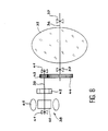
- a motor 38 performs the rotational movement, thanks to a transmission which comprises a motor shaft 39 attached to the rotor 40 of the motor 38 and the position of which is defined by bearings 41, a dynamic balancing ring 42 if necessary established on the motor shaft 39, a pinion 43, and a toothed wheel 44 meshing in the pinion 43 is linked to the axis 36.
- R is called the reduction ratio between the pinion 43 and the toothed wheel 44
- R Imi / Imo
- Imi is the sum of the inertias of the aiming mirror 35 , of the axis 36 and of the toothed wheel 44
- Imo the sum of the inertias of the rotor 40, of the motor shaft 39, of the dynamic balancing ring 42 and of the pinion 43. If this relation is respected, the kinetic moments of the rotating parts cancel out regardless of the amplitude of the movement of the rotor 40 and the m aiming iror 35. No angular momentum is therefore transmitted to the rest of the satellite by the stator 45 of the motor 38. The balance of the satellite is not disturbed.
Landscapes
- Engineering & Computer Science (AREA)
- Remote Sensing (AREA)
- Automation & Control Theory (AREA)
- Chemical & Material Sciences (AREA)
- Combustion & Propulsion (AREA)
- Radar, Positioning & Navigation (AREA)
- Aviation & Aerospace Engineering (AREA)
- Control Of Position, Course, Altitude, Or Attitude Of Moving Bodies (AREA)
- Toys (AREA)
Claims (12)
- Künstlicher Satellit, dadurch gekennzeichnet, daß an der Vorderseite und an der Rückseite des Hauptkörpers (1), in dem sich der Massemittelpunkt (0) des Satelliten befindet, entlang der Längsachse (Xs) mobile aerodynamische Nicksteuereinrichtungen (5, 5', 5") angeordnet sind, die sich um die Querachsen (11) drehen, senkrecht zur Längsachse stehen und symmetrisch zur mittleren Längsebene (XsZs) angeordnet sind, wobei die Längsachse in der senkrecht zur Querachse (11) stehenden Längsebene verläuft und den Massemittelpunkt des Satelliten schneidet.
- Künstlicher Satellit gemäß Anspruch 1, dadurch gekennzeichnet, daß die Nicksteuereinrichtungen so gebaut sind, daß hinter ihnen keine Funkschatten entstehen.
- Künstlicher Satellit gemäß Anspruch 2, dadurch gekennzeichnet, daß die vom Hauptkörper (1) abgewandten Steuereinrichtungen an den Enden Frontklappen (13) aufweisen.
- Künstlicher Satellit gemäß Anspruch 2, dadurch gekennzeichnet, daß die Nicksteuereinrichtungen aus Platten (14) zusammengesetzt sind, die sich in Richtung der Querachsen verstärken.
- Künstlicher Satellit, gemäß Anspruch 2, dadurch gekennzeichnet, daß die Nicksteuereinrichtungen aus einem Leinenband (50) bestehen, das über Rollen (51) nahe dem Hauptkörper (1) gewickelt und zwischen den Rollen durch einen Teleskoparm (53) gehalten wird.
- Künstlicher Satellit gemäß einem der Ansprüche 1 bis 5, dadurch gekennzeichnet, daß er auf zwei in Bezug auf den Hauptkörper gegenüberliegenden Seiten entlang der mittleren Längsebene (XsZs) aus aerodynamischen Roll- und Giersteuereinrichtungen (4, 4') besteht. die sich um die Querachsen (21, 31, 32) drehen.
- Künstlicher Satellit gemäß Anspruch 6, dadurch gekennzeichnet, daß die Roll- und Giersteuereinrichtungen paarweise symmetrisch zur mittleren Längsebene des Satelliten angeordnet sind.
- Künstlicher Satellit gemäß Anspruch 7, dadurch gekennzeichnet, daß er mindestens zwei Paar Roll- und Giersteuereinrichtungen umfaßt.
- Künstlicher Satellit gemäß einem der Ansprüche 6 bis 8, dadurch gekennzeichnet, daß die Roll- und Giersteuereinrichtungen (4') so konzipiert sind, daß sie reine Gierbewegungen erzeugen und aus zwei Platteneinheiten (23, 24) bestehen. die durch einen Motor (27) im Gegensinn gedreht werden, wobei der Motor zwei Getriebe (28, 29) antreibt, die zu den entsprechenden Platteneinheiten führen.
- Künstlicher Satellit gemäß einem der Ansprüche 8 und 9, dadurch gekennzeichnet, daß er aus einem Paar Steuereinrichtungen (4) besteht, die zum Erzeugen reiner Rollbewegungen im Gegensinn bewegt werden.
- Künstlicher Satellit gemäß einem der Ansprüche 1 bis 10, dadurch gekennzeichnet, daß die drehenden Objekte (35) durch Motoren (38) und Getriebe (36, 39) angetrieben werden, und daß jedes System, das aus einem dieser Objekte besteht, sowie jeder Motor, der das genannte Objekt bewegt und jeder Antrieb, der den genannten Motor mit dem genannten Objekt verbindet, einen Drehimpuls von Null besitzt, wenn der Motor das Objekt bewegt.
- Künstlicher Satellit gemäß Anspruch 11, dadurch gekennzeichnet, daß die drehenden Objekte mindestens einige Steuereinrichtungen enthalten.
Applications Claiming Priority (3)
| Application Number | Priority Date | Filing Date | Title |
|---|---|---|---|
| FR9304953A FR2704515B1 (fr) | 1993-04-27 | 1993-04-27 | Satellite artificiel muni de gouvernes aerodynamiques d'orientation. |
| FR9304953 | 1993-04-27 | ||
| PCT/FR1994/000480 WO1994025344A1 (fr) | 1993-04-27 | 1994-04-27 | Satellite artificiel muni de gouvernes aerodynamiques d'orientation |
Publications (2)
| Publication Number | Publication Date |
|---|---|
| EP0696252A1 EP0696252A1 (de) | 1996-02-14 |
| EP0696252B1 true EP0696252B1 (de) | 1996-11-13 |
Family
ID=9446484
Family Applications (1)
| Application Number | Title | Priority Date | Filing Date |
|---|---|---|---|
| EP94915182A Expired - Lifetime EP0696252B1 (de) | 1993-04-27 | 1994-04-27 | Satellit mit aerodynamischer steuereinrichtung |
Country Status (8)
| Country | Link |
|---|---|
| US (1) | US5716031A (de) |
| EP (1) | EP0696252B1 (de) |
| JP (1) | JPH08509443A (de) |
| AU (1) | AU6652994A (de) |
| CA (1) | CA2161549A1 (de) |
| DE (1) | DE69400921T2 (de) |
| FR (1) | FR2704515B1 (de) |
| WO (1) | WO1994025344A1 (de) |
Families Citing this family (15)
| Publication number | Priority date | Publication date | Assignee | Title |
|---|---|---|---|---|
| FR2718105B1 (fr) | 1994-03-30 | 1996-06-14 | Centre Nat Etd Spatiales | Satellite artificiel muni de générateurs de moments magnétiques et aérodynamiques et procédé de commande d'un tel satellite. |
| USD401209S (en) | 1997-01-28 | 1998-11-17 | Gaiter Kenneth M | Vehicle for use in outer space as a space probe, planetary rover or spaceship |
| RU2134219C1 (ru) * | 1998-04-02 | 1999-08-10 | Волков Ефим Ефимович | Космическая термомеханическая система ориентации на солнце |
| AU5572499A (en) * | 1998-08-19 | 2000-03-14 | Mobile Communications Holdings, Inc. | Adaptively positioned solar array |
| FR2836450B1 (fr) * | 2002-02-25 | 2004-12-03 | Centre Nat Etd Spatiales | Vehicule spatial et procede de pilotage d'un tel vehicule |
| US7097127B2 (en) * | 2003-06-24 | 2006-08-29 | The Boeing Company | Mass trim mechanism |
| US7104506B1 (en) * | 2003-08-06 | 2006-09-12 | Lockheed Martin Corporation | Spacecraft disturbance trimming system |
| FR2897843B1 (fr) * | 2006-02-27 | 2009-03-06 | Eads Space Transp Sas Soc Par | Voilure d'aerofreinage de satellite |
| US9889950B2 (en) * | 2015-02-20 | 2018-02-13 | Space Systems/Loral, Llc | Spacecraft with aerodynamic control |
| US10647450B2 (en) * | 2016-03-18 | 2020-05-12 | The Boeing Company | Satellite control system using electrically controllable variable reflection glass panels |
| US20210284361A1 (en) * | 2019-07-17 | 2021-09-16 | Skeyeon, Inc. | Systems and methods for attitude control for a satellite |
| FR3105180B1 (fr) | 2019-12-18 | 2021-12-24 | Airbus Defence & Space Sas | Dispositif d’orientation d’une charge selon deux axes de rotation orthogonaux |
| WO2020254984A2 (en) * | 2020-06-17 | 2020-12-24 | Alhubail Jasem | An apparatus for controlling a spacecraft's atmospheric reentry |
| CN112591150B (zh) * | 2021-01-05 | 2022-09-13 | 成都天巡微小卫星科技有限责任公司 | 一种控制超低轨道卫星姿态的大气阻力矩补偿方法及系统 |
| CN117755522A (zh) * | 2023-09-20 | 2024-03-26 | 湖南赛德雷特空间科技有限公司 | 一种用于维纳卫星三维姿态指向伸缩机构的操作方法 |
Family Cites Families (8)
| Publication number | Priority date | Publication date | Assignee | Title |
|---|---|---|---|---|
| US3258224A (en) * | 1962-07-30 | 1966-06-28 | Thompson Ramo Wooldridge Inc | Attitude stabilization of spacecraft |
| US3184187A (en) * | 1963-05-10 | 1965-05-18 | Isaac Peter | Retractable airfoils and hydrofoils |
| US3304028A (en) * | 1964-08-11 | 1967-02-14 | Hugh L Dryden | Attitude control for spacecraft |
| FR2513589A1 (fr) * | 1981-09-28 | 1983-04-01 | Aerospatiale | Procede et dispositif pour aligner l'axe de roulis d'un satellite avec une direction desiree |
| FR2530046A1 (fr) * | 1982-07-06 | 1984-01-13 | Matra | Procede et dispositif de commande d'attitude pour satellite geosynchrone |
| FR2679515B1 (fr) * | 1991-07-26 | 1996-01-26 | Onera (Off Nat Aerospatiale) | Voilure solaire. |
| US5350138A (en) * | 1993-03-15 | 1994-09-27 | University Corporation For Atmospheric Research | Low-cost shuttle-derived space station |
| US5487791A (en) * | 1994-05-25 | 1996-01-30 | Aec Able Engineering Co., Inc. | Stowable and self-deployable parallelogram-type panel array |
-
1993
- 1993-04-27 FR FR9304953A patent/FR2704515B1/fr not_active Expired - Fee Related
-
1994
- 1994-04-27 US US08/535,214 patent/US5716031A/en not_active Expired - Fee Related
- 1994-04-27 DE DE69400921T patent/DE69400921T2/de not_active Expired - Fee Related
- 1994-04-27 WO PCT/FR1994/000480 patent/WO1994025344A1/fr not_active Ceased
- 1994-04-27 JP JP6523959A patent/JPH08509443A/ja active Pending
- 1994-04-27 AU AU66529/94A patent/AU6652994A/en not_active Abandoned
- 1994-04-27 EP EP94915182A patent/EP0696252B1/de not_active Expired - Lifetime
- 1994-04-27 CA CA002161549A patent/CA2161549A1/fr not_active Abandoned
Also Published As
| Publication number | Publication date |
|---|---|
| JPH08509443A (ja) | 1996-10-08 |
| AU6652994A (en) | 1994-11-21 |
| FR2704515B1 (fr) | 1995-07-13 |
| EP0696252A1 (de) | 1996-02-14 |
| FR2704515A1 (fr) | 1994-11-04 |
| WO1994025344A1 (fr) | 1994-11-10 |
| DE69400921D1 (de) | 1996-12-19 |
| DE69400921T2 (de) | 1997-05-15 |
| US5716031A (en) | 1998-02-10 |
| CA2161549A1 (fr) | 1994-11-10 |
Similar Documents
| Publication | Publication Date | Title |
|---|---|---|
| EP0696252B1 (de) | Satellit mit aerodynamischer steuereinrichtung | |
| EP1484247B1 (de) | Gyroskopischer Stellantrieb, insbesondere für die Lageregelung eines Satelliten | |
| CA2834593C (fr) | Dispositif de deploiement et de reploiement d'une structure flexible, structure deployable flexible et satellite munis d'un tel dispositif | |
| EP0436425B1 (de) | System zur Steuerung der Lage eines stabilisierten Satelliten durch Solarzellen | |
| EP0754143B1 (de) | Künstlicher satellit mit aerodynamischen und magnetischen drehmomentgebern und steuerungsverfahren für einen derartigen satelliten | |
| EP3083269B1 (de) | Kugelförmiges rad zum bewegen eines fahrzeuges und fahrzeug mit dem rad | |
| FR2513589A1 (fr) | Procede et dispositif pour aligner l'axe de roulis d'un satellite avec une direction desiree | |
| FR2529166A1 (fr) | Procede de maintien en position d'un satellite par la navigation a l'aide de voiles solaires et vehicule spatial mettant en oeuvre le procede | |
| EP3956219B1 (de) | Antriebsvorrichtung für einen drehflügler mit senkrechtstart und -landung und ein drehflügler mit mindestens einer solchen antriebsvorrichtung | |
| FR2789653A1 (fr) | Satellite a generateur solaire sur bras depliable et procede de mise a poste d'un tel satellite | |
| US20100307290A1 (en) | Apparatus, system and method for gyroscopic propulsion and/or steering | |
| US20070012124A1 (en) | Centrifugal propulsion engine | |
| EP1165369B1 (de) | Pendelgesteuerter hubschrauber mit hoher stabilität und grosser manövrierbarkeit | |
| FR2679515A1 (fr) | Voilure solaire. | |
| EP1452830B1 (de) | Gyroskopisches stellglied | |
| BE552058A (de) | ||
| FR2577198A1 (fr) | Avion convertible | |
| EP0047212B1 (de) | Eine Translations- und Rotationsbewegung kombinierende Spreizvorrichtung, insbesondere für die Ausrüstung eines Raumflugkörpers | |
| FR2911655A1 (fr) | Dispositif mecanique generateur de mouvement | |
| FR2651017A1 (fr) | Dispositif d'orientation des pales d'un rotor dans un flux transversal de fluide et application de celui-ci | |
| FR2711111A1 (fr) | Engin spatial à voile solaire et procédé de pilotage d'un tel engin. | |
| BE825667A (fr) | Dispositif de poussee | |
| JPH06297977A (ja) | 差動装置のトルク分配機構 | |
| FR2738930A1 (fr) | Procede et dispositif passif de pointage d'un engin spatial vers le soleil | |
| US20230013388A1 (en) | Impulse mover |
Legal Events
| Date | Code | Title | Description |
|---|---|---|---|
| PUAI | Public reference made under article 153(3) epc to a published international application that has entered the european phase |
Free format text: ORIGINAL CODE: 0009012 |
|
| 17P | Request for examination filed |
Effective date: 19951026 |
|
| AK | Designated contracting states |
Kind code of ref document: A1 Designated state(s): CH DE ES FR GB IT LI NL SE |
|
| GRAG | Despatch of communication of intention to grant |
Free format text: ORIGINAL CODE: EPIDOS AGRA |
|
| 17Q | First examination report despatched |
Effective date: 19960313 |
|
| GRAH | Despatch of communication of intention to grant a patent |
Free format text: ORIGINAL CODE: EPIDOS IGRA |
|
| GRAH | Despatch of communication of intention to grant a patent |
Free format text: ORIGINAL CODE: EPIDOS IGRA |
|
| GRAA | (expected) grant |
Free format text: ORIGINAL CODE: 0009210 |
|
| AK | Designated contracting states |
Kind code of ref document: B1 Designated state(s): CH DE ES FR GB IT LI NL SE |
|
| PG25 | Lapsed in a contracting state [announced via postgrant information from national office to epo] |
Ref country code: ES Free format text: THE PATENT HAS BEEN ANNULLED BY A DECISION OF A NATIONAL AUTHORITY Effective date: 19961113 |
|
| REF | Corresponds to: |
Ref document number: 69400921 Country of ref document: DE Date of ref document: 19961219 |
|
| ITF | It: translation for a ep patent filed | ||
| PG25 | Lapsed in a contracting state [announced via postgrant information from national office to epo] |
Ref country code: SE Effective date: 19970213 |
|
| GBT | Gb: translation of ep patent filed (gb section 77(6)(a)/1977) |
Effective date: 19970123 |
|
| PLBE | No opposition filed within time limit |
Free format text: ORIGINAL CODE: 0009261 |
|
| STAA | Information on the status of an ep patent application or granted ep patent |
Free format text: STATUS: NO OPPOSITION FILED WITHIN TIME LIMIT |
|
| 26N | No opposition filed | ||
| REG | Reference to a national code |
Ref country code: GB Ref legal event code: IF02 |
|
| PGFP | Annual fee paid to national office [announced via postgrant information from national office to epo] |
Ref country code: DE Payment date: 20030419 Year of fee payment: 10 |
|
| PGFP | Annual fee paid to national office [announced via postgrant information from national office to epo] |
Ref country code: GB Payment date: 20030423 Year of fee payment: 10 |
|
| PGFP | Annual fee paid to national office [announced via postgrant information from national office to epo] |
Ref country code: FR Payment date: 20030428 Year of fee payment: 10 |
|
| PGFP | Annual fee paid to national office [announced via postgrant information from national office to epo] |
Ref country code: NL Payment date: 20030429 Year of fee payment: 10 Ref country code: CH Payment date: 20030429 Year of fee payment: 10 |
|
| PG25 | Lapsed in a contracting state [announced via postgrant information from national office to epo] |
Ref country code: GB Free format text: LAPSE BECAUSE OF NON-PAYMENT OF DUE FEES Effective date: 20040427 |
|
| PG25 | Lapsed in a contracting state [announced via postgrant information from national office to epo] |
Ref country code: LI Free format text: LAPSE BECAUSE OF NON-PAYMENT OF DUE FEES Effective date: 20040430 Ref country code: CH Free format text: LAPSE BECAUSE OF NON-PAYMENT OF DUE FEES Effective date: 20040430 |
|
| PG25 | Lapsed in a contracting state [announced via postgrant information from national office to epo] |
Ref country code: NL Free format text: LAPSE BECAUSE OF NON-PAYMENT OF DUE FEES Effective date: 20041101 |
|
| PG25 | Lapsed in a contracting state [announced via postgrant information from national office to epo] |
Ref country code: DE Free format text: LAPSE BECAUSE OF NON-PAYMENT OF DUE FEES Effective date: 20041103 |
|
| GBPC | Gb: european patent ceased through non-payment of renewal fee |
Effective date: 20040427 |
|
| REG | Reference to a national code |
Ref country code: CH Ref legal event code: PL |
|
| PG25 | Lapsed in a contracting state [announced via postgrant information from national office to epo] |
Ref country code: FR Free format text: LAPSE BECAUSE OF NON-PAYMENT OF DUE FEES Effective date: 20041231 |
|
| NLV4 | Nl: lapsed or anulled due to non-payment of the annual fee |
Effective date: 20041101 |
|
| REG | Reference to a national code |
Ref country code: FR Ref legal event code: ST |
|
| PG25 | Lapsed in a contracting state [announced via postgrant information from national office to epo] |
Ref country code: IT Free format text: LAPSE BECAUSE OF NON-PAYMENT OF DUE FEES;WARNING: LAPSES OF ITALIAN PATENTS WITH EFFECTIVE DATE BEFORE 2007 MAY HAVE OCCURRED AT ANY TIME BEFORE 2007. THE CORRECT EFFECTIVE DATE MAY BE DIFFERENT FROM THE ONE RECORDED. Effective date: 20050427 |