EP0696406B1 - Endoskop mit einem an seiner spitze angeordneten ccd-farbsensor - Google Patents
Endoskop mit einem an seiner spitze angeordneten ccd-farbsensor Download PDFInfo
- Publication number
- EP0696406B1 EP0696406B1 EP94913976A EP94913976A EP0696406B1 EP 0696406 B1 EP0696406 B1 EP 0696406B1 EP 94913976 A EP94913976 A EP 94913976A EP 94913976 A EP94913976 A EP 94913976A EP 0696406 B1 EP0696406 B1 EP 0696406B1
- Authority
- EP
- European Patent Office
- Prior art keywords
- endoscope
- tube
- lens
- charge
- distal end
- Prior art date
- Legal status (The legal status is an assumption and is not a legal conclusion. Google has not performed a legal analysis and makes no representation as to the accuracy of the status listed.)
- Expired - Lifetime
Links
Images


Classifications
-
- H—ELECTRICITY
- H04—ELECTRIC COMMUNICATION TECHNIQUE
- H04N—PICTORIAL COMMUNICATION, e.g. TELEVISION
- H04N23/00—Cameras or camera modules comprising electronic image sensors; Control thereof
- H04N23/56—Cameras or camera modules comprising electronic image sensors; Control thereof provided with illuminating means
-
- A—HUMAN NECESSITIES
- A61—MEDICAL OR VETERINARY SCIENCE; HYGIENE
- A61B—DIAGNOSIS; SURGERY; IDENTIFICATION
- A61B1/00—Instruments for performing medical examinations of the interior of cavities or tubes of the body by visual or photographical inspection, e.g. endoscopes; Illuminating arrangements therefor
- A61B1/04—Instruments for performing medical examinations of the interior of cavities or tubes of the body by visual or photographical inspection, e.g. endoscopes; Illuminating arrangements therefor combined with photographic or television appliances
- A61B1/05—Instruments for performing medical examinations of the interior of cavities or tubes of the body by visual or photographical inspection, e.g. endoscopes; Illuminating arrangements therefor combined with photographic or television appliances characterised by the image sensor, e.g. camera, being in the distal end portion
-
- H—ELECTRICITY
- H04—ELECTRIC COMMUNICATION TECHNIQUE
- H04N—PICTORIAL COMMUNICATION, e.g. TELEVISION
- H04N23/00—Cameras or camera modules comprising electronic image sensors; Control thereof
- H04N23/50—Constructional details
- H04N23/55—Optical parts specially adapted for electronic image sensors; Mounting thereof
-
- H—ELECTRICITY
- H04—ELECTRIC COMMUNICATION TECHNIQUE
- H04N—PICTORIAL COMMUNICATION, e.g. TELEVISION
- H04N23/00—Cameras or camera modules comprising electronic image sensors; Control thereof
- H04N23/50—Constructional details
- H04N23/555—Constructional details for picking-up images in sites, inaccessible due to their dimensions or hazardous conditions, e.g. endoscopes or borescopes
Definitions
- the present invention relates to a video endoscope and, more particularly, to an endoscope provided with a charge coupled device (CCD) located at the distal end of the endoscope.
- CCD charge coupled device
- the present invention corrects the deficiencies of the prior art by providing a video endoscopic imaging system designed to be used in the same procedures as the conventional rigid and flexible endoscopes which are currently in use.
- This device effectively replaces the standard rigid optical lens systems which are currently employed and substitutes a CCD chip directly producing a chromatic output, for the standard CCD chip now utilized in endoscopes which directly produces a non-chromatic output.
- This new CCD chip is also provided in the distal end of the endoscope.
- the signal produced at each point in the field of view of the endoscope of the present invention is proportional to the brightness of the color which achieves full color images.
- the CCD During each moment of time, the CCD according to the present invention, records a color image of the scene as it appears under that particular color of illumination and transmits it to a video system center which, in turn, feeds it to a color monitor.
- the color fidelity of the video image is enhanced since, throughout the entire imaging system, from the CCD sensor chip to the monitor display screen, precise control over color reproduction is established and maintained.
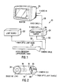
- the general system of the present invention 10 is illustrated in Figs. 1 and 2. These figures show an endoscope 12 having a distal end 14. A rigid endoscope is shown in these figures, but it should be noted that the present invention could also include the use of a flexible endoscope.
- the distal portion 14 of the endoscope 12 includes an objective lens combination 16 provided between a cover glass 34 and a CCD color chip 18. Although the particular color CCD is not important, it is noted that the present invention works particularly well utilizing a CCD color chip and processing circuit designated as Panasonic Model No. GP-KS 202.
- This CCD color chip consists of a large number of solid state image pickup devices which convert a picture signal, at each point on the CCD based upon the brightness which is sensed at that point, directly to a chromatic output. These chromatic output signals are transferred to a video system center 24 by wires 20 provided within the endoscope 12 and by a cable 30. Although a number of different controls could be associated with the video system center 24, the system presently contemplates the use of an on/off button 34, as well as an automatic or manual light balance control 36.
- the present CCD color chip which is utilized, produces an analog signal which is transmitted to the video system center 24 provided with a number of processing circuits for converting the analog signals into digital signals and then back to analog signals before they are transmitted to a standard monitor 26 via an electrical cable 28.
- the present system would operate if chromatic digital signals were directly produced by the CCD color chip 18. These digital signals would then be sent over wires 20 and cable 30 to the video system center 24. These signals would then be processed, and either analog or digital signals would be transmitted to the monitor 26 using the cable 28.
- a standard light source 22 This light source is external to the endoscope 12 and is connected thereto by a fiber optic light guide 32 provided with a fiber optic light bundle 38 therein. As noted in Fig. 2, the fiber optic light bundle 38 surrounds the inner periphery of the endoscope 12 and extends a small distance beyond the cover glass 34.
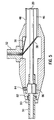
- Fig. 3 illustrates a side view of the endoscope shown partially in sections.
- the distal end 14 of the endoscope is shown in slightly more detail than is illustrated in Fig. 1.
- the distal portion 14 includes a stand-alone lens housing section 16 provided with first and second objective lenses 40,42 separated by a lens diaphragm 44.
- the focal length of this lens portion of the endoscope is determined, and the opening of the aperture within the diaphragm 44 as well as the dimensions of the lenses 40 and 42, as well as their composition, are chosen accordingly.
- the endoscope 12 is provided with an inner tube 46 as well as an outer tube 48.
- the fiber optic bundles 38 are provided between the outside surface of the inner tube 46 and the inside surface of the outer tube 48.
- the cable connecting the CCD color chip 18 to the video system center 24 extends through the center of the inner tube 48 and through the cable 30.
- the light source 22 is connected to the fiber optic light bundle 38 by a light post terminator 52 provided on the proximal end 50 of the endoscope body.
- a strain relief and grounding portion 56 is provided on the proximal end 50 of the endoscope 12, through which the cable 30 extends.
- the diameter of the outer tube is 10 mm
- the diameter of the inner tube is 8.6 mm. Therefore, the diameter of the CCD color chip 18 must be equal to or less than 8.6 mm.
- the dimension of the outer tube and the inner tube could be increased or decreased.
- the objective lens housing 16 is shown in Fig. 4.
- the housing 16 is attached between the cover glass 38 and the CCD color chip 18.
- the housing includes lenses 40 and 42 separated from one another by a lens diagram 44 having an aperture 64 therein and a spacer element 60.
- the present invention utilizes a fixed focus lens which is not designed to alter its focal length once it has been installed in the endoscope and calibrated.
- a nut 66 is provided between the cover glass 38 and a spacer 62 provided in front of lens 42, and is used to properly position the lens housing within the endoscope.
- the lens housing is threaded at 60 to allow longitudinal movement of the lens housing using a special tool to turn the nut 66.
- a filter assembly 75 is provided between the lens assembly and is directly glued onto the CCD chip 18 by an adhesive 70.
- the filter 75 includes crystal filters 68, 74 and 76, as well as an infrared filter 72.
- Fig. 5 illustrates the proximal end 50 of the endoscope.
- the light fibers 38 which extend between the outer periphery of the inner tube 46 and the inner periphery of the outer tube 48, pass through the light post termination section 52 and are connected to the light source 22 using the fiber optic light guide 32.
- a strain relief nut 80 and O-ring 82 are included for stability.
- a grounding set screw 84 and brass clip ring 86 are employed to protect against interference of the signal produced by the CCD chip 18.
- the entire endoscope 12 as well as the cable 30 are manufactured from materials which allow them to be sterilized by soaking them in a solution of Cidex.
- a silicon sheath is provided over the cable 30.
Landscapes
- Engineering & Computer Science (AREA)
- Health & Medical Sciences (AREA)
- Life Sciences & Earth Sciences (AREA)
- Multimedia (AREA)
- Signal Processing (AREA)
- Surgery (AREA)
- Biomedical Technology (AREA)
- Molecular Biology (AREA)
- Optics & Photonics (AREA)
- Pathology (AREA)
- Radiology & Medical Imaging (AREA)
- Biophysics (AREA)
- Physics & Mathematics (AREA)
- Heart & Thoracic Surgery (AREA)
- Medical Informatics (AREA)
- Nuclear Medicine, Radiotherapy & Molecular Imaging (AREA)
- Animal Behavior & Ethology (AREA)
- General Health & Medical Sciences (AREA)
- Public Health (AREA)
- Veterinary Medicine (AREA)
- Endoscopes (AREA)
- Instruments For Viewing The Inside Of Hollow Bodies (AREA)
- Closed-Circuit Television Systems (AREA)
- Color Television Image Signal Generators (AREA)
Claims (6)
- Endoskop (12) zum Betrachten einer Szene innerhalb eines menschlichen oder tierischen Körpers, miteinem langgestreckten Rohr (48) mit einem entfernten (14) und einem naheliegenden (50) Ende, wobei in dem Rohr folgende Elemente angeordnet sind:ein Objektivlinsensystem (16) am entfernten Ende mit ersten und zweiten Linsen (40, 42), eine Linsenblende (44) zwischen den beiden Linsen und mit einer Öffnung (64), ein erster Abstandshalter (62) auf derjenigen Seite der ersten Linse, welche der zweiten Linse abgekehrt ist, und ein zweiter Abstandshalter (60) zwischen der Blende und der zweiten Linse sowieein farbempfindliches ladungsgekoppeltes Bauelement (18) mit einer maximalen Dimension in Querrichtung, die gleich oder geringer als der Innendurchmesser des Rohres ist, in welchem das Bauelement montiert und auf der optischen Achse des Linsensystems positioniert ist, wobei das ladungsgekoppelte Bauelement in der Lage ist, ein Ausgangssignal aufgrund der betrachteten Szene zu liefern und dieses von dem entfernten Ende zu dem naheliegenden Ende zu übertragen.
- Endoskop nach Anspruch 1, mit einem zwischen dem Linsensystem und dem ladungsgekoppelten Bauelement angeordneten optischen Filter (75), welches zumindest zwei Kristallfilter (68, 74, 76) und ein Infrarotfilter (72) enthält.
- Endoskop nach Anspruch 1 oder 2, bei welchem das Rohr (48) in seinem Inneren mit radialem Abstand ein weiteres Rohr (46) enthält und in dem Abstand ein Bündel optischer Fasern (38), sich von dem entfernten zu dem naheliegenden Ende des äußeren Rohres erstreckend, angeordnet ist.
- Endoskop nach Anspruch 3, bei welchem der Außendurchmesser des äußeren Rohres nicht größer als 10 mm und der Innendurchmesser des inneren Rohres nicht größer als 8,6 mm ist.
- Endoskop nach einem der vorhergehenden Ansprüche, mit einem außerhalb des Rohres (48) angeordneten Signalverarbeitungsschaltkreis (24) in solcher elektrischer Verbindung, daß er das Ausgangssignal empfängt, und einem mit dem Schaltkreis verbunden Monitor (26) zur Wiedergabe der betrachteten Szene.
- Endoskop nach einem der vorhergehenden Ansprüche, mit einer in das Rohr (48) an seinem entfernten Ende (14) eingeschraubten Hülse (66), die eine innenliegende Schulter zur Abstützung des ersten Abstandshalters aufweist, wobei eine Drehung der Hülse die Entfernung zwischen dem optischen System und dem Rohrende zu Fokusierungszwecken verändert.
Applications Claiming Priority (3)
| Application Number | Priority Date | Filing Date | Title |
|---|---|---|---|
| US4390493A | 1993-04-07 | 1993-04-07 | |
| US43904 | 1993-04-07 | ||
| PCT/US1994/003431 WO1994023539A1 (en) | 1993-04-07 | 1994-04-06 | Endoscope provided with a distally located color ccd |
Publications (3)
| Publication Number | Publication Date |
|---|---|
| EP0696406A1 EP0696406A1 (de) | 1996-02-14 |
| EP0696406A4 EP0696406A4 (de) | 1996-04-10 |
| EP0696406B1 true EP0696406B1 (de) | 1999-03-03 |
Family
ID=21929506
Family Applications (1)
| Application Number | Title | Priority Date | Filing Date |
|---|---|---|---|
| EP94913976A Expired - Lifetime EP0696406B1 (de) | 1993-04-07 | 1994-04-06 | Endoskop mit einem an seiner spitze angeordneten ccd-farbsensor |
Country Status (7)
| Country | Link |
|---|---|
| US (1) | US5594497A (de) |
| EP (1) | EP0696406B1 (de) |
| JP (1) | JPH08511383A (de) |
| AT (1) | ATE177278T1 (de) |
| AU (1) | AU6622494A (de) |
| DE (1) | DE69416829D1 (de) |
| WO (1) | WO1994023539A1 (de) |
Families Citing this family (75)
| Publication number | Priority date | Publication date | Assignee | Title |
|---|---|---|---|---|
| US5902230A (en) * | 1995-02-06 | 1999-05-11 | Asahi Kogaku Kogyo Kabushiki Kaisha | Electronic endoscope system with information combined in digital output |
| JP3681781B2 (ja) * | 1995-02-08 | 2005-08-10 | オリンパス株式会社 | 電子内視鏡 |
| US5879306A (en) * | 1996-06-13 | 1999-03-09 | Stryker Corporation | Infrared system for visualizing body members |
| DE19647855B4 (de) * | 1996-11-19 | 2007-09-27 | Henke-Sass Wolf Gmbh | Voll autoklavierbares elektronisches Endoskop |
| DE69938493T2 (de) | 1998-01-26 | 2009-05-20 | Massachusetts Institute Of Technology, Cambridge | Endoskop zur erfassung von fluoreszenzbilder |
| US6364829B1 (en) | 1999-01-26 | 2002-04-02 | Newton Laboratories, Inc. | Autofluorescence imaging system for endoscopy |
| FR2785132B1 (fr) * | 1998-10-27 | 2000-12-22 | Tokendo Sarl | Sonde videoendoscopique a capteur ccd couleur distal |
| DE60024059T2 (de) | 1999-01-26 | 2006-07-20 | Newton Laboratories, Inc., Woburn | Vorrichtung zur autofluoreszensbildgebung für ein endoskop |
| US8248457B2 (en) | 1999-02-25 | 2012-08-21 | Visionsense, Ltd. | Optical device |
| US6396873B1 (en) | 1999-02-25 | 2002-05-28 | Envision Advanced Medical Systems | Optical device |
| US7683926B2 (en) * | 1999-02-25 | 2010-03-23 | Visionsense Ltd. | Optical device |
| US7154527B1 (en) | 1999-02-25 | 2006-12-26 | Visionsense Ltd. | Optical device |
| US7116352B2 (en) | 1999-02-25 | 2006-10-03 | Visionsense Ltd. | Capsule |
| FR2793893B1 (fr) * | 1999-05-21 | 2002-07-19 | Renault | Dispositif de visualisation par camera numerique miniature |
| DE19947811C2 (de) | 1999-10-05 | 2002-06-20 | Winter & Ibe Olympus | Endoskop mit elektrischer Einrichtung und Lichtleiter |
| DE10003198A1 (de) * | 2000-01-25 | 2001-07-26 | Wolfgang F Schmidt | Körpersonde |
| IL135571A0 (en) * | 2000-04-10 | 2001-05-20 | Doron Adler | Minimal invasive surgery imaging system |
| US6692430B2 (en) * | 2000-04-10 | 2004-02-17 | C2Cure Inc. | Intra vascular imaging apparatus |
| US9113846B2 (en) * | 2001-07-26 | 2015-08-25 | Given Imaging Ltd. | In-vivo imaging device providing data compression |
| US20050187433A1 (en) * | 2001-07-26 | 2005-08-25 | Given Imaging Ltd. | In-vivo imaging device providing constant bit rate transmission |
| CA2469773A1 (en) * | 2001-12-11 | 2003-07-03 | C2Cure Inc. | Apparatus, method and system for intravascular photographic imaging |
| US8614768B2 (en) * | 2002-03-18 | 2013-12-24 | Raytheon Company | Miniaturized imaging device including GRIN lens optically coupled to SSID |
| US20060146172A1 (en) * | 2002-03-18 | 2006-07-06 | Jacobsen Stephen C | Miniaturized utility device having integrated optical capabilities |
| US7591780B2 (en) * | 2002-03-18 | 2009-09-22 | Sterling Lc | Miniaturized imaging device with integrated circuit connector system |
| US7787939B2 (en) * | 2002-03-18 | 2010-08-31 | Sterling Lc | Miniaturized imaging device including utility aperture and SSID |
| WO2003098913A2 (en) * | 2002-05-16 | 2003-11-27 | Cbyond Inc. | Miniature camera head |
| DE10307904A1 (de) | 2003-02-18 | 2004-10-21 | Karl Storz Gmbh & Co. Kg | Endoskop und Verfahren zum Montieren von Bauelementen eines optischen Systems |
| IL155175A (en) * | 2003-03-31 | 2012-01-31 | Given Imaging Ltd | A diagnostic device that uses information thinning |
| WO2004096032A1 (en) | 2003-04-29 | 2004-11-11 | Aircraft Medical Limited | Laryngoscope with camera attachment |
| US7300397B2 (en) * | 2004-07-29 | 2007-11-27 | C2C Cure, Inc. | Endoscope electronics assembly |
| US20060164510A1 (en) * | 2005-01-24 | 2006-07-27 | Doron Adler | Sensor with narrow mounting profile |
| US20060221218A1 (en) * | 2005-04-05 | 2006-10-05 | Doron Adler | Image sensor with improved color filter |
| US7835074B2 (en) * | 2007-06-05 | 2010-11-16 | Sterling Lc | Mini-scope for multi-directional imaging |
| US20090046171A1 (en) * | 2007-08-16 | 2009-02-19 | C2Cure, Inc. | Non-linear color correction |
| US7969659B2 (en) * | 2008-01-11 | 2011-06-28 | Sterling Lc | Grin lens microscope system |
| US20090287048A1 (en) * | 2008-05-16 | 2009-11-19 | Sterling Lc | Method and apparatus for imaging within a living body |
| JP5596027B2 (ja) | 2008-06-18 | 2014-09-24 | レイセオン カンパニー | カテーテル |
| WO2010014792A2 (en) | 2008-07-30 | 2010-02-04 | Sterling Lc | Method and device for incremental wavelength variation to analyze tissue |
| WO2010053916A2 (en) | 2008-11-04 | 2010-05-14 | Sterling Lc | Method and device for wavelength shifted imaging |
| US9795442B2 (en) | 2008-11-11 | 2017-10-24 | Shifamed Holdings, Llc | Ablation catheters |
| WO2011041728A2 (en) | 2009-10-01 | 2011-04-07 | Jacobsen Stephen C | Needle delivered imaging device |
| WO2011041720A2 (en) | 2009-10-01 | 2011-04-07 | Jacobsen Stephen C | Method and apparatus for manipulating movement of a micro-catheter |
| WO2011041730A2 (en) | 2009-10-01 | 2011-04-07 | Jacobsen Stephen C | Light diffusion apparatus |
| US8828028B2 (en) | 2009-11-03 | 2014-09-09 | Raytheon Company | Suture device and method for closing a planar opening |
| CA2797130A1 (en) | 2010-05-12 | 2011-11-17 | Shifamed Holdings, Llc | Low profile electrode assembly |
| US9655677B2 (en) | 2010-05-12 | 2017-05-23 | Shifamed Holdings, Llc | Ablation catheters including a balloon and electrodes |
| EP2708021B1 (de) | 2011-05-12 | 2019-07-10 | DePuy Synthes Products, Inc. | Bildsensor mit toleranzoptimierenden verbindungen |
| MX346174B (es) | 2012-07-26 | 2017-03-10 | Depuy Synthes Products Inc | Esquema de iluminacion pulsada ycbcr en un entorno deficiente de luz. |
| BR112015001369A2 (pt) | 2012-07-26 | 2017-07-04 | Olive Medical Corp | sistema de câmera com sensor de imagem cmos monolítico de área mínima |
| AU2013295553B2 (en) | 2012-07-26 | 2017-10-19 | DePuy Synthes Products, Inc. | Continuous video in a light deficient environment |
| US10322194B2 (en) | 2012-08-31 | 2019-06-18 | Sloan-Kettering Institute For Cancer Research | Particles, methods and uses thereof |
| US20140139658A1 (en) * | 2012-11-20 | 2014-05-22 | General Electric Company | Remote visual inspection system and method |
| JP6465811B2 (ja) | 2012-12-19 | 2019-02-06 | スローン − ケタリング・インスティテュート・フォー・キャンサー・リサーチ | 多様式の粒子、方法およびその使用 |
| US20160000329A1 (en) | 2013-02-20 | 2016-01-07 | Sloan-Kettering Institute For Cancer Research | Wide field raman imaging apparatus and associated methods |
| US20140350534A1 (en) * | 2013-02-20 | 2014-11-27 | Sloan-Kettering Institute For Cancer Research | Raman based ablation/resection systems and methods |
| CA2906821A1 (en) | 2013-03-15 | 2014-09-18 | Olive Medical Corporation | Scope sensing in a light controlled environment |
| JP2016519591A (ja) | 2013-03-15 | 2016-07-07 | オリーブ・メディカル・コーポレイションOlive Medical Corporation | パルスカラー撮像システムにおける超解像度及び色運動アーチファクト補正 |
| CA2906832A1 (en) | 2013-03-15 | 2014-09-18 | Olive Medical Corporation | Viewing trocar with intergrated prism for use with angled endoscope |
| EP2967285B1 (de) | 2013-03-15 | 2023-08-16 | DePuy Synthes Products, Inc. | Bildsensorsynchronisierung ohne eingangstakt und datenübertragungstakt |
| JP6404318B2 (ja) | 2013-03-15 | 2018-10-10 | デピュイ・シンセス・プロダクツ・インコーポレイテッド | レーザーパルスの積算光エネルギー制御 |
| CN105228503B (zh) | 2013-03-15 | 2017-11-07 | 德普伊新特斯产品公司 | 最小化内窥镜应用中图像传感器输入/输出和导体的数量 |
| US10098694B2 (en) | 2013-04-08 | 2018-10-16 | Apama Medical, Inc. | Tissue ablation and monitoring thereof |
| CN110141177B (zh) | 2013-04-08 | 2021-11-23 | 阿帕玛医疗公司 | 消融导管 |
| US10349824B2 (en) | 2013-04-08 | 2019-07-16 | Apama Medical, Inc. | Tissue mapping and visualization systems |
| US9257763B2 (en) | 2013-07-02 | 2016-02-09 | Gyrus Acmi, Inc. | Hybrid interconnect |
| US9510739B2 (en) | 2013-07-12 | 2016-12-06 | Gyrus Acmi, Inc. | Endoscope small imaging system |
| US10912947B2 (en) | 2014-03-04 | 2021-02-09 | Memorial Sloan Kettering Cancer Center | Systems and methods for treatment of disease via application of mechanical force by controlled rotation of nanoparticles inside cells |
| AU2015230978B2 (en) | 2014-03-21 | 2020-01-23 | DePuy Synthes Products, Inc. | Card edge connector for an imaging sensor |
| US10688202B2 (en) | 2014-07-28 | 2020-06-23 | Memorial Sloan-Kettering Cancer Center | Metal(loid) chalcogen nanoparticles as universal binders for medical isotopes |
| DE102014222986B4 (de) * | 2014-11-11 | 2019-05-02 | Siemens Healthcare Gmbh | Anordnung und Verfahren zur Positionierung einer Komponente in einem Comutertomographie-Untersuchungsraum |
| US10919089B2 (en) | 2015-07-01 | 2021-02-16 | Memorial Sloan Kettering Cancer Center | Anisotropic particles, methods and uses thereof |
| CN108348146A (zh) | 2015-11-16 | 2018-07-31 | 阿帕玛医疗公司 | 能量传递装置 |
| JP6727951B2 (ja) * | 2016-06-24 | 2020-07-22 | 三菱重工サーマルシステムズ株式会社 | 電動圧縮機の電線導入部構造、これを備えたシールド電線、および電動圧縮機 |
| WO2019135956A1 (en) | 2018-01-04 | 2019-07-11 | Applied Medical Resources Corporation | Surgical simulation camera scope |
| US11382487B2 (en) | 2018-04-03 | 2022-07-12 | Curadel, LLC | Micro CMOS scopes for medical imaging |
Family Cites Families (20)
| Publication number | Priority date | Publication date | Assignee | Title |
|---|---|---|---|---|
| US3456641A (en) * | 1964-09-30 | 1969-07-22 | Tokyo Shibaura Electric Co | Flexible endoscope for photographing diseased parts in cancer diagnosis |
| US4253447A (en) * | 1978-10-16 | 1981-03-03 | Welch Allyn, Inc. | Color endoscope with charge coupled device and television viewing |
| JPS6053919A (ja) * | 1983-09-05 | 1985-03-28 | Olympus Optical Co Ltd | 内視鏡用撮像装置 |
| DE3526993A1 (de) * | 1984-07-31 | 1986-02-13 | Olympus Optical Co., Ltd., Tokio/Tokyo | Blendenanordnung einer lichtquelle fuer ein endoskop |
| JPH0644105B2 (ja) * | 1985-01-14 | 1994-06-08 | オリンパス光学工業株式会社 | 内視鏡 |
| JPS6343639A (ja) * | 1986-08-11 | 1988-02-24 | オリンパス光学工業株式会社 | 電子内視鏡 |
| US4918521A (en) * | 1987-01-20 | 1990-04-17 | Olympus Optical Co., Ltd. | Solid state imaging apparatus |
| US4853772A (en) * | 1987-02-26 | 1989-08-01 | Olympus Optical Co., Ltd. | Electronic endoscope apparatus having isolated patient and secondary circuitry |
| US4858001A (en) * | 1987-10-08 | 1989-08-15 | High-Tech Medical Instrumentation, Inc. | Modular endoscopic apparatus with image rotation |
| US5143054A (en) * | 1988-12-28 | 1992-09-01 | Adair Edwin Lloyd | Cervical videoscope with detachable camera unit |
| US5026368A (en) * | 1988-12-28 | 1991-06-25 | Adair Edwin Lloyd | Method for cervical videoscopy |
| US4905670A (en) * | 1988-12-28 | 1990-03-06 | Adair Edwin Lloyd | Apparatus for cervical videoscopy |
| USRE33854E (en) * | 1989-02-03 | 1992-03-24 | sterilizable sheathpe with .[.heat.]. | |
| US4878485A (en) * | 1989-02-03 | 1989-11-07 | Adair Edwin Lloyd | Rigid video endoscope with heat sterilizable sheath |
| USRE34002E (en) * | 1989-02-03 | 1992-07-21 | Sterilizable video camera cover | |
| JP2991299B2 (ja) * | 1989-08-04 | 1999-12-20 | 株式会社東芝 | 内視鏡装置 |
| US4979498A (en) * | 1989-10-30 | 1990-12-25 | Machida Incorporated | Video cervicoscope system |
| US5125395A (en) * | 1990-09-12 | 1992-06-30 | Adair Edwin Lloyd | Deflectable sheath for optical catheter |
| JPH0775400B2 (ja) * | 1990-12-28 | 1995-08-09 | 松下電器産業株式会社 | 固体撮像装置のカメラヘッド及びその製造方法 |
| US5188094A (en) * | 1991-09-30 | 1993-02-23 | Adair Edwin Lloyd | Heat sterilizable electronic video endoscope |
-
1994
- 1994-04-06 DE DE69416829T patent/DE69416829D1/de not_active Expired - Lifetime
- 1994-04-06 WO PCT/US1994/003431 patent/WO1994023539A1/en not_active Ceased
- 1994-04-06 EP EP94913976A patent/EP0696406B1/de not_active Expired - Lifetime
- 1994-04-06 JP JP6522309A patent/JPH08511383A/ja not_active Ceased
- 1994-04-06 AU AU66224/94A patent/AU6622494A/en not_active Abandoned
- 1994-04-06 AT AT94913976T patent/ATE177278T1/de active
-
1995
- 1995-12-20 US US08/575,463 patent/US5594497A/en not_active Expired - Fee Related
Also Published As
| Publication number | Publication date |
|---|---|
| EP0696406A4 (de) | 1996-04-10 |
| ATE177278T1 (de) | 1999-03-15 |
| US5594497A (en) | 1997-01-14 |
| EP0696406A1 (de) | 1996-02-14 |
| DE69416829D1 (de) | 1999-04-08 |
| JPH08511383A (ja) | 1996-11-26 |
| WO1994023539A1 (en) | 1994-10-13 |
| AU6622494A (en) | 1994-10-24 |
Similar Documents
| Publication | Publication Date | Title |
|---|---|---|
| US5594497A (en) | Endoscope provided with a distally located color CCD | |
| US4600940A (en) | Video camera for use with an endoscope and method for making same | |
| US7063663B2 (en) | Endoscopic system with a solid-state light source | |
| US4860732A (en) | Endoscope apparatus provided with endoscope insertion aid | |
| US4905082A (en) | Rigid video endoscope having a detachable imaging unit | |
| US5124797A (en) | Modular view lens attachment for micro video imaging camera | |
| US5325847A (en) | Distal end part of endoscope | |
| US5498230A (en) | Sterile connector and video camera cover for sterile endoscope | |
| US4781448A (en) | Zoom lens adapter for endoscopic camera | |
| US5512036A (en) | Dental imaging system | |
| WO1996039916A1 (en) | Asymmetric stereo-optic endoscope | |
| US4600939A (en) | Focusable video camera for use with endoscopes | |
| US4600938A (en) | Focusable video camera for use with endoscopes | |
| JP3386187B2 (ja) | 硬性内視鏡装置 | |
| JP2902691B2 (ja) | モニタ画像撮影装置 | |
| JPH01293840A (ja) | 根管内視鏡 | |
| JPH06130305A (ja) | 電子内視鏡 | |
| JPS6199484A (ja) | 内視鏡 | |
| JP3214046B2 (ja) | 電子内視鏡装置 | |
| JP3149177B2 (ja) | 電子内視鏡 | |
| JP3076655B2 (ja) | 内視鏡のライトガイドコネクタ装置 | |
| JP3114239B2 (ja) | 狭所挿入型観察装置 | |
| JPS6115117A (ja) | Tv内視鏡 | |
| JPH02289225A (ja) | 内視鏡用外付けテレビカメラ装置 | |
| JP2000241718A (ja) | 電子内視鏡及び内視鏡装置 |
Legal Events
| Date | Code | Title | Description |
|---|---|---|---|
| PUAI | Public reference made under article 153(3) epc to a published international application that has entered the european phase |
Free format text: ORIGINAL CODE: 0009012 |
|
| 17P | Request for examination filed |
Effective date: 19951013 |
|
| AK | Designated contracting states |
Kind code of ref document: A1 Designated state(s): AT BE CH DE DK ES FR GB GR IE IT LI LU MC NL PT SE |
|
| A4 | Supplementary search report drawn up and despatched |
Effective date: 19960219 |
|
| AK | Designated contracting states |
Kind code of ref document: A4 Designated state(s): AT BE CH DE DK ES FR GB GR IE IT LI LU MC NL PT SE |
|
| RAP1 | Party data changed (applicant data changed or rights of an application transferred) |
Owner name: AHERN, JOHN M. |
|
| 17Q | First examination report despatched |
Effective date: 19970806 |
|
| GRAG | Despatch of communication of intention to grant |
Free format text: ORIGINAL CODE: EPIDOS AGRA |
|
| GRAG | Despatch of communication of intention to grant |
Free format text: ORIGINAL CODE: EPIDOS AGRA |
|
| GRAG | Despatch of communication of intention to grant |
Free format text: ORIGINAL CODE: EPIDOS AGRA |
|
| GRAH | Despatch of communication of intention to grant a patent |
Free format text: ORIGINAL CODE: EPIDOS IGRA |
|
| GRAH | Despatch of communication of intention to grant a patent |
Free format text: ORIGINAL CODE: EPIDOS IGRA |
|
| GRAA | (expected) grant |
Free format text: ORIGINAL CODE: 0009210 |
|
| AK | Designated contracting states |
Kind code of ref document: B1 Designated state(s): AT BE CH DE DK ES FR GB GR IE IT LI LU MC NL PT SE |
|
| PG25 | Lapsed in a contracting state [announced via postgrant information from national office to epo] |
Ref country code: SE Free format text: THE PATENT HAS BEEN ANNULLED BY A DECISION OF A NATIONAL AUTHORITY Effective date: 19990303 Ref country code: NL Free format text: LAPSE BECAUSE OF FAILURE TO SUBMIT A TRANSLATION OF THE DESCRIPTION OR TO PAY THE FEE WITHIN THE PRESCRIBED TIME-LIMIT Effective date: 19990303 Ref country code: LI Free format text: LAPSE BECAUSE OF FAILURE TO SUBMIT A TRANSLATION OF THE DESCRIPTION OR TO PAY THE FEE WITHIN THE PRESCRIBED TIME-LIMIT Effective date: 19990303 Ref country code: IT Free format text: LAPSE BECAUSE OF FAILURE TO SUBMIT A TRANSLATION OF THE DESCRIPTION OR TO PAY THE FEE WITHIN THE PRE;WARNING: LAPSES OF ITALIAN PATENTS WITH EFFECTIVE DATE BEFORE 2007 MAY HAVE OCCURRED AT ANY TIME BEFORE 2007. THE CORRECT EFFECTIVE DATE MAY BE DIFFERENT FROM THE ONE RECORDED.SCRIBED TIME-LIMIT Effective date: 19990303 Ref country code: GR Free format text: LAPSE BECAUSE OF NON-PAYMENT OF DUE FEES Effective date: 19990303 Ref country code: FR Free format text: LAPSE BECAUSE OF FAILURE TO SUBMIT A TRANSLATION OF THE DESCRIPTION OR TO PAY THE FEE WITHIN THE PRESCRIBED TIME-LIMIT Effective date: 19990303 Ref country code: ES Free format text: THE PATENT HAS BEEN ANNULLED BY A DECISION OF A NATIONAL AUTHORITY Effective date: 19990303 Ref country code: CH Free format text: LAPSE BECAUSE OF FAILURE TO SUBMIT A TRANSLATION OF THE DESCRIPTION OR TO PAY THE FEE WITHIN THE PRESCRIBED TIME-LIMIT Effective date: 19990303 Ref country code: BE Free format text: LAPSE BECAUSE OF FAILURE TO SUBMIT A TRANSLATION OF THE DESCRIPTION OR TO PAY THE FEE WITHIN THE PRESCRIBED TIME-LIMIT Effective date: 19990303 Ref country code: AT Free format text: LAPSE BECAUSE OF FAILURE TO SUBMIT A TRANSLATION OF THE DESCRIPTION OR TO PAY THE FEE WITHIN THE PRESCRIBED TIME-LIMIT Effective date: 19990303 |
|
| REF | Corresponds to: |
Ref document number: 177278 Country of ref document: AT Date of ref document: 19990315 Kind code of ref document: T |
|
| REG | Reference to a national code |
Ref country code: CH Ref legal event code: EP |
|
| REG | Reference to a national code |
Ref country code: IE Ref legal event code: FG4D |
|
| PG25 | Lapsed in a contracting state [announced via postgrant information from national office to epo] |
Ref country code: LU Free format text: LAPSE BECAUSE OF NON-PAYMENT OF DUE FEES Effective date: 19990406 |
|
| REF | Corresponds to: |
Ref document number: 69416829 Country of ref document: DE Date of ref document: 19990408 |
|
| PG25 | Lapsed in a contracting state [announced via postgrant information from national office to epo] |
Ref country code: IE Free format text: LAPSE BECAUSE OF NON-PAYMENT OF DUE FEES Effective date: 19990503 |
|
| PG25 | Lapsed in a contracting state [announced via postgrant information from national office to epo] |
Ref country code: DK Free format text: LAPSE BECAUSE OF FAILURE TO SUBMIT A TRANSLATION OF THE DESCRIPTION OR TO PAY THE FEE WITHIN THE PRESCRIBED TIME-LIMIT Effective date: 19990603 |
|
| PG25 | Lapsed in a contracting state [announced via postgrant information from national office to epo] |
Ref country code: PT Free format text: LAPSE BECAUSE OF FAILURE TO SUBMIT A TRANSLATION OF THE DESCRIPTION OR TO PAY THE FEE WITHIN THE PRESCRIBED TIME-LIMIT Effective date: 19990604 |
|
| PG25 | Lapsed in a contracting state [announced via postgrant information from national office to epo] |
Ref country code: DE Free format text: LAPSE BECAUSE OF FAILURE TO SUBMIT A TRANSLATION OF THE DESCRIPTION OR TO PAY THE FEE WITHIN THE PRESCRIBED TIME-LIMIT Effective date: 19990605 |
|
| EN | Fr: translation not filed | ||
| NLV1 | Nl: lapsed or annulled due to failure to fulfill the requirements of art. 29p and 29m of the patents act | ||
| REG | Reference to a national code |
Ref country code: CH Ref legal event code: PL |
|
| PG25 | Lapsed in a contracting state [announced via postgrant information from national office to epo] |
Ref country code: MC Free format text: LAPSE BECAUSE OF NON-PAYMENT OF DUE FEES Effective date: 19991031 |
|
| PLBE | No opposition filed within time limit |
Free format text: ORIGINAL CODE: 0009261 |
|
| STAA | Information on the status of an ep patent application or granted ep patent |
Free format text: STATUS: NO OPPOSITION FILED WITHIN TIME LIMIT |
|
| 26N | No opposition filed | ||
| PGFP | Annual fee paid to national office [announced via postgrant information from national office to epo] |
Ref country code: GB Payment date: 20000306 Year of fee payment: 7 |
|
| PG25 | Lapsed in a contracting state [announced via postgrant information from national office to epo] |
Ref country code: GB Free format text: LAPSE BECAUSE OF NON-PAYMENT OF DUE FEES Effective date: 20010406 |
|
| GBPC | Gb: european patent ceased through non-payment of renewal fee |
Effective date: 20010406 |