EP0696702B1 - Ensemble équilibreur - Google Patents
Ensemble équilibreur Download PDFInfo
- Publication number
- EP0696702B1 EP0696702B1 EP94305940A EP94305940A EP0696702B1 EP 0696702 B1 EP0696702 B1 EP 0696702B1 EP 94305940 A EP94305940 A EP 94305940A EP 94305940 A EP94305940 A EP 94305940A EP 0696702 B1 EP0696702 B1 EP 0696702B1
- Authority
- EP
- European Patent Office
- Prior art keywords
- housing
- holder
- horizontal axle
- holders
- knob
- Prior art date
- Legal status (The legal status is an assumption and is not a legal conclusion. Google has not performed a legal analysis and makes no representation as to the accuracy of the status listed.)
- Expired - Lifetime
Links
- 230000002093 peripheral effect Effects 0.000 claims 2
- 238000004091 panning Methods 0.000 description 7
- 230000007246 mechanism Effects 0.000 description 6
- 230000005540 biological transmission Effects 0.000 description 4
- 230000003247 decreasing effect Effects 0.000 description 3
- 230000005484 gravity Effects 0.000 description 3
- 239000012530 fluid Substances 0.000 description 2
- 238000013459 approach Methods 0.000 description 1
- 125000004122 cyclic group Chemical group 0.000 description 1
- 238000006073 displacement reaction Methods 0.000 description 1
- 239000004519 grease Substances 0.000 description 1
- 238000004519 manufacturing process Methods 0.000 description 1
- 230000002035 prolonged effect Effects 0.000 description 1
Images


Classifications
-
- F—MECHANICAL ENGINEERING; LIGHTING; HEATING; WEAPONS; BLASTING
- F16—ENGINEERING ELEMENTS AND UNITS; GENERAL MEASURES FOR PRODUCING AND MAINTAINING EFFECTIVE FUNCTIONING OF MACHINES OR INSTALLATIONS; THERMAL INSULATION IN GENERAL
- F16M—FRAMES, CASINGS OR BEDS OF ENGINES, MACHINES OR APPARATUS, NOT SPECIFIC TO ENGINES, MACHINES OR APPARATUS PROVIDED FOR ELSEWHERE; STANDS; SUPPORTS
- F16M11/00—Stands or trestles as supports for apparatus or articles placed thereon ; Stands for scientific apparatus such as gravitational force meters
- F16M11/02—Heads
- F16M11/04—Means for attachment of apparatus; Means allowing adjustment of the apparatus relatively to the stand
- F16M11/06—Means for attachment of apparatus; Means allowing adjustment of the apparatus relatively to the stand allowing pivoting
- F16M11/10—Means for attachment of apparatus; Means allowing adjustment of the apparatus relatively to the stand allowing pivoting around a horizontal axis
-
- F—MECHANICAL ENGINEERING; LIGHTING; HEATING; WEAPONS; BLASTING
- F16—ENGINEERING ELEMENTS AND UNITS; GENERAL MEASURES FOR PRODUCING AND MAINTAINING EFFECTIVE FUNCTIONING OF MACHINES OR INSTALLATIONS; THERMAL INSULATION IN GENERAL
- F16M—FRAMES, CASINGS OR BEDS OF ENGINES, MACHINES OR APPARATUS, NOT SPECIFIC TO ENGINES, MACHINES OR APPARATUS PROVIDED FOR ELSEWHERE; STANDS; SUPPORTS
- F16M2200/00—Details of stands or supports
- F16M2200/04—Balancing means
- F16M2200/041—Balancing means for balancing rotational movement of the head
Definitions
- the present invention relates to a counterbalancing unit. More particularly, the present invention relates to a counterbalancing unit for a tripod head capable of generating an appropriate amount of restoring force in proportion to a torque created when a tripod head is tilted and thus enabling a photographing device, such as a still camera, a video camera or a movie camera, mounted on the tripod head to tilt stably and smoothly.
- the invention also relates to such a counterbalancing unit in which the said restoring force may be adjusted corresponding to the weight of a photographing device.
- a tripod head has been conventionally used as a device for mounting a photographing device such as a still camera, a video camera or movie camera on a tripod and for permitting a smooth tilting rotation of the photographing device.
- a counterbalancing means is incorporated in such a tripod head to prevent the photographing device from quickly rotating and falling due to the torque created by the movement of its centre of gravity when it is tilted.
- Such a counterbalancing means is a means by which a restoring force in proportion to a torque caused by displacement of the center of gravity of the photographing device is generated by an elastic body such as spring. The restoring force prevents the photographing device from falling and thus allows it to be tilted stably and smoothly.
- Such a counterbalancing means for a tripod head is disclosed in Japanese publication No. 27560/90 and Japanese Utility Model Publication No. 13037/91, for example.
- a crank or cam which rotates eccentrically in accordance with the tilting rotation of the tripod head, is applied to the means described in those publications.
- many elements have to be incorporated in such mechanisms, and therefore the design work is complex. Further, since the mechanism has a complicated structure, it is expensive, and its operation is not always reliable.
- a counterbalancing unit for a tripod head comprising:
- Such an arrangement provides a suitable restoring force in proportion to the torque created during tilting rotation of a tripod head, and simplifies the structure of the counterbalancing unit.
- a photographing device such as a still camera, a video camera or a movie camera, may thus be tilted stably and smoothly, the counterbalancing unit is manufactured more easily, and the cost of manufacture is reduced.
- a base 1 of a tripod head has secured thereto a housing 2 which extends vertically from the base 1.
- Side walls 3 of the housing 2 have openings at their centers in which hub members of arms 5 are rotatably mounted through bearings 4.
- a mount 6a and a mounting plate 6b for mounting a photographing device such as a still camera, a video camera or a movie camera, are fixed to the top portions of the arms 5.
- the arms 5 can be rotated about a horizontal axis, supported by the side walls 3 of the housing 2. This allows the photographing device to be tilted.
- a horizontal axle 7 is disposed in the middle of the tripod head and is coaxial with the central axis around which the arms 5 are tilted. This horizontal axle 7 is arranged to be rotatable and is also movable along its horizontal axis.
- a pair of right-hand and left-hand holders 8a and 8b are located in the housing 2 and slidable on the horizontal axle 7.
- a plurality of shafts 9 extend through the holders 8a and 8b, parallel to the axle 7, and are secured to the side walls 3 at their ends. The holders 8a and 8b are thus mounted on the shafts 9. Springs 10 are compressed between the holders 8a and 8b, so as to push the holders apart.
- the left-hand holder 8a thereby comes into contact with a washer 11 fixed on the left-hand end of the horizontal axle 7, through a bearing 12.
- a bearing 12 There is no particular limitation with regard to the number of the shafts 9 and the springs 10. Their number can be chosen according to the weight of a photographing device to be mounted, for example.
- Two guide pins 13, one of which extends upward and the other of which extends downward, are rotatably mounted in the right-hand holder 8b by way of bearings 14. These guide pins 13 are slidable along the longitudinal axle 7 together with the holder 8b. In some cases only one guide pin 13 need be provided, which may extend upward or downward, or indeed horizontally. The number of guide pins 13 may be varied.
- a rotary member 15 is fixed on the inside of the right-hand rotary arm 5.
- the edge of the rotary member 15 presses against the sides of the guide pins 13 under the elastic force of the springs 10 disposed between the holders 8a and 8b.
- the rotary member 15 thus acts to push the guide pins 13 and the holder 8b inwardly of the arm 5.
- the rotary member 15 has a cam face 16 on its edge.
- This cam face 16 is a smoothly curved face, and engages the sides of the guide pins 13.
- the cam face 16 is formed into a curved face with repeated undulations in a cycle of 180 degrees.
- the undulations allow the tripod head to be tilted within a limited range of tilting rotation, specifically 90 degrees forward and 75 degrees backward.
- peak portions 17 are provided corresponding to the extremes of the tilting rotation
- valley portions 18 are interposed between the peak portions 17 corresponding to the less tilted state. These peak and valley portions 17 and 18 are also disposed in cycles of 180 degrees.
- cam face 16 engaging the sides of the pins 13 to smoothly transform from a valley portion 18 to a peak portion 17 and thereby cause the guide pins 13 to be moved in the left-hand direction as seen in FIG. 1.
- Such a cyclic surface permits peak portions 17 and valley portions 18 to be disposed in a rotation symmetry as illustrated in FIG. 2A.
- the rotary member 15 comes into contact with the respective guide pins 13 and pushes them to move the same distance in a horizontal direction.
- the shape of the cam face 16 is not limited to that depicted in FIGs. 2 and 3. It can be chosen depending on the location, the number and the desired distance of the movement of the guide pins 13. It is possible, for example, to design the shape of the cam face 16 to correspond to a tilting rotation in the range of 90 degrees both forward and backward.
- a knob 20 is rotatably mounted on the outside of the right-hand arm 5 through a bearing 19.
- the knob 20 is for adjusting the amount of restoring force in proportion to the weight of a photographing device to be mounted.
- a member 21 having a threaded portion at its tip is connected to the knob 20.
- a threaded axial bore is formed in the right-hand end of the horizontal axle 7, which is engaged with the threaded member 21.
- the right-hand end of the horizontal axle 7 is slidable in a keyway 23 in a space 22 formed in the middle of the arm 5.
- the left-hand holder 8a is similarly moved to the right by the washer 11, horizontally along the shafts 9.
- This movement of the holder 8a in the right-hand direction further compresses the springs 10, thereby increasing the elastic force of the springs and generating an increased restoring force when the tripod head is tilted.
- the restoring force may thus be increased to balance the weight of a photographing device to be mounted on the tripod head.
- Such an adjustment of the restoring force can be carried out when a photographing device is mounted on the tripod head or when it is not mounted. It may be carried out during a tilting rotation. The operation is simple and easy.
- the counterbalancing unit as described above operates as follows.
- the restoring force becomes correspondingly larger so as to balance the increased torque, and thus a counterbalanced state is always maintained, thereby preventing the photographing device from unexpectedly rotating and falling.
- the restoring force is adjustable to correspond to various weights of photographing devices.
- a counterbalancing unit for a tripod head generates an appropriate restoring force in proportion to the torque produced during the tilting rotation, so that a photographing device may be tilted stably and smoothly.
- the structure of the counterbalancing unit is relatively simple so that the tripod head is easily manufactured at a reduced cost.
- guide pins 13 are connected with the right-hand holder 8b at both of their ends by way of bearings 14. This ensures more stable movement of the guide pins.
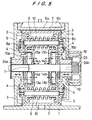
- this embodiment has a similar structure to that of FIG. 1. Although shafts 9 and springs 10 are not shown in FIG. 4, these members are still provided between the holders 8a and 8b. A keyway 23 is also again provided in the space 22.
- a pair of guide pins 13a and 13b is associated with each of the holders 8a and 8b, extending upward and downward as before.
- Two rotary members 15a and 15b having cam faces at their edges are disposed face to face on the horizontal axle 7, the cam faces again contacting the sides of the guide pins 13a and 13b.
- These rotary members 15a and 15b are movably connected with tiltable arms 5 and are horizontally movable by rotation of a knob 20.
- the horizontal axle 7 cannot move horizontally, but it can still rotate. More specifically, the knob 20 is fixed to the right-hand end of the axle 7, and rotation of the knob 20 thus causes the axle to rotate.
- First threaded portions 24a and 24b are symmetrically formed on the respective ends of the horizontal axle 7.
- Second threaded portions (not shown) are formed on the inner surfaces of the rotary members 15a and 15b and are engaged with the first threaded portions 24a and 24b.
- the restoring force applied at the time of tilting rotation in the embodiment of FIG. 5, as well as in those of FIGs. 1 and 4, varies depending on the torque, and a counterbalancing state is always maintained.
- the rotary members 15a and 15b rotate according to the tilting rotation, pushing the guide pins 13a and 13b inwardly, whereby the holders 8a and 8b are moved inward along the shafts 9, and the springs 10 are compressed.
- the rotary members 15a and 15b rotate in the opposite direction, the holders 8a and 8b are pushed apart under the influence of the springs 10, and the guide pins 13a and 13b return to their original positions while keeping in contact with the cam faces of the rotary members 15a and 15b.
- the elastic force becomes smaller in proportion to decrease of the torque, and thereby, the counterbalancing state is maintained.
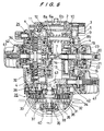
- the counterbalancing unit here shown has basically the same structure as that of FIG. 1.
- the left-hand side wall 3 is integrated with the housing 2.
- a tripod head includes a counterbalancing unit and brake units 25 which are connected with the left-hand side and the bottom of housing 2, respectively.
- an elastic body in the form of an auxiliary spring 26, distinct from springs 10, is provided between the left-hand holder 8a and a left-hand side of the housing 2 which corresponds to the left-side side wall 3 of FIG. 1.
- This auxiliary spring 26 is arranged to exert its elastic force to push the holder 8a to the right, namely toward the holder 8b.
- the auxiliary spring 26 allows a knob 20 to be smoothly operated to adjust the restoring force and also has the function of helping the horizontal axle 7 to move to the right when the restoring force of springs 10 is being caused to increase. Consequently the torque required to rotate the knob 20 is reduced.
- the location of the elastic body 26 is not limited to what is shown in FIG. 6.
- Such an elastic body may for example be arranged between a holder 8b and a right-hand side wall 3. Neither is there any particular limitation with regard to the number of such elastic bodies. They may be appropriately provided to correspond to the restoring force which is generated during a tilting rotation.
- a counterbalancing unit as described above may be combined with a brake unit 25, as shown in FIG. 6, such a combination providing a tripod head having multiple functions.
- a brake unit 25 as shown in FIG. 6 is a means for modifying the speed of movement during horizontal panning and tiling rotations of a tripod head.
- the brake unit 25 provided at the bottom of the housing 2 is for horizontal panning rotation, while the unit 25 on the left-hand side of the housing is for tilting rotation.
- a case 32 having a plurality of projections 31 coaxially disposed on its bottom inner surface is provided in the brake unit 25.
- a braking disc 33 is provided in the case 32 and is movable in the direction of those projections 31.
- a plurality of projections 34 are coaxially provided on the braking device 33 and are received in the spaces between the projections 31 of the case 32 and between the outermost of such projections and the inner side of the case 32. Through holes 35 and 36 extend through projections 34 and the bottom of the braking disc 33.
- the braking disc 33 In the brake unit for horizontal panning rotation, the braking disc 33 is connected so as to rotate according to the rotation of the tripod head. On the other hand, in the brake unit for tilting rotation, the case 32 is so rotatably connected.
- the case 32 is sealed, and viscous fluid such as grease is filled in an inner sealed space of the case.
- viscous fluid such as grease
- the braking disc 33 slides along a supporting shaft 37 in these brake units 25.
- the position of braking disc 33 in the case 32 is adjusted to modify the braking force. More specifically, the braking force becomes large when the projections 34 of the braking disc 33 are further engaged with the projections 31 of the case 32. On the other hand, the less the engagement of these projections 31 and 34 becomes, the smaller is the braking force.
- These changes in the engagement between projections 31 and 34 are effected by sliding movement of the braking disc 33. During such movement of the braking disc, the viscous fluid filled in the case 32 flows through the holes 35 and 36 and thus does not impede such movement.
- the braking disc 33 is connected with a sliding shaft 39 through a pin 38.
- Elongate holes 40 through which the pin 38 extends are formed in a hollow supporting shaft 37, and the sliding shaft 39 is thus slidable within the range of the length of the elongate holes 40 along the inner surface of the supporting shaft 37.
- the sliding shaft 39 supports the braking disc 33 through the pin 38 during its sliding movement.
- the sliding shaft 39 is connected with an operating knob 41 disposed in the front of the tripod head, via a transmission mechanism 42. The braking force is adjusted by rotating the operating knob 41.
- a threaded portion is provided with the transmission mechanism 42, through which rotation of the operating knob 41 is transmitted to the sliding shaft 39 to move the tip of the sliding shaft 39 forward and backward.
- the structure of the transmission mechanism 42 is slightly different as between one for horizontal panning rotation and one for tilting rotation.
- a brake operating plate 42 rotatable in a vertical plane is provided and transforms horizontal sliding movement of the threaded portion into vertical movement of the sliding shaft 39. This is because it is not possible to connect the threaded portion with the tip of the sliding shaft 39 directly in the brake unit for horizontal panning rotation.
- the threaded portion of the transmission mechanism 42 is directly connected with the tip of the sliding shaft 39 in the brake unit for tilting operation.
Landscapes
- Engineering & Computer Science (AREA)
- General Engineering & Computer Science (AREA)
- Mechanical Engineering (AREA)
- Accessories Of Cameras (AREA)
Claims (5)
- Unité de compensation pour tête de trépied, comportant :un axe horizontal (7) ;un premier élément de maintien (8b) supporté d'une manière coulissante sur ledit axe horizontal et disposé dans un boítier (2, 3) s'étendant verticalement à partir de la base (1) d'une tête de trépied ;un corps élastique comprimé (10) ;au moins une tige de guidage (13) reliée au premier élément de maintien et pouvant se déplacer vers l'intérieur dudit boítier, en association avec ledit élément de maintien, lorsque ladite tête de trépied est inclinée ; etun élément rotatif (15) ayant une face de came (16) au niveau d'un bord de celui-ci et fixé à un bras (5) supporté d'une manière inclinable sur ledit boítier, ledit élément rotatif tournant avec ledit bras et amenant ladite tige de guidage à se déplacer vers l'intérieur dans ledit boítier par l'intermédiaire de ladite face de came lorsque ladite tête de trépied est inclinée, de manière à comprimer davantage ledit corps élastique comprimé ;
ladite unité de compensation générant une force de rappel proportionnelle à un couple créé lorsque ladite tête de trépied est inclinée ;
caractérisée en ce que l'unité de compensation comporte en outre :un second élément de maintien (8a) supporté d'une manière coulissante sur ledit axe horizontal (7) et disposé à l'intérieur du boítier (2, 3) en formant une paire d'éléments de maintien (8a, 8b) avec le premier élément de maintien (8b) ; etune pluralité d'arbres (9) s'étendant à travers les éléments de maintien, parallèlement à l'axe horizontal, et étant fixés au boítier (3) au niveau de ses extrémités, les éléments de maintien pouvant se déplacer horizontalement le long des arbres,et en ce qu'un corps élastique comprimé (10) est monté autour de chacun des arbres et est supporté et comprimé entre la paire d'éléments de maintien. - Unité de compensation selon la revendication 1, comportant en outre :un bouton (20) pour ajuster une force élastique des corps élastiques (10) comprimés, ayant un élément fileté (21), et monté de manière à pouvoir tourner à l'avant dudit bras (5) ;un trou fileté étant formé au niveau d'une première extrémité dudit axe horizontal (7) et recevant ledit élément fileté ;
dans laquelle la rotation dudit bouton et dudit élément fileté provoque le déplacement de l'axe horizontal dans une direction horizontale. - Unité de compensation selon la revendication 2, dans laquelle ledit second élément de maintien (8a), qui ne comporte pas de tige de guidage (13), est monté sur l'extrémité dudit axe horizontal (7) en vis-à-vis de l'extrémité comportant ledit trou fileté ;la rotation dudit bouton (20) amenant ledit corps élastique (10) comprimé à être davantage comprimé entre lesdits éléments de maintien.
- Unité de compensation selon la revendication 1, comportant en outre :un bouton (20) pour ajuster la force élastique dudit corps élastique (10) comprimé, monté à l'avant dudit bras, ledit bouton étant fixé sur ledit axe horizontal (7) de manière à faire tourner avec lui ledit axe,une première partie filetée (24a, 24b) formée sur une surface périphérique extérieure d'une extrémité dudit axe horizontal ; etune seconde partie filetée formée sur une surface périphérique intérieure dudit élément rotatif (15a, 15b) et venant en prise avec ladite première partie filetée,la rotation dudit bouton amenant ledit élément rotatif à se déplacer horizontalement.
- Unité de compensation selon l'une quelconque des revendications précédentes, comportant en outre au moins un corps élastique auxiliaire (26) agencé entre ledit boítier (2, 3) et au moins l'un desdits éléments de maintien (8a), ledit corps élastique auxiliaire amenant ledit élément de maintien à être repoussé vers l'intérieur dudit boítier.
Priority Applications (3)
| Application Number | Priority Date | Filing Date | Title |
|---|---|---|---|
| US08/287,896 US5553821A (en) | 1994-08-09 | 1994-08-09 | Counterbalancing unit |
| EP94305940A EP0696702B1 (fr) | 1994-08-09 | 1994-08-11 | Ensemble équilibreur |
| DE1994623750 DE69423750T2 (de) | 1994-08-11 | 1994-08-11 | Ausgleicheinheit |
Applications Claiming Priority (2)
| Application Number | Priority Date | Filing Date | Title |
|---|---|---|---|
| US08/287,896 US5553821A (en) | 1994-08-09 | 1994-08-09 | Counterbalancing unit |
| EP94305940A EP0696702B1 (fr) | 1994-08-09 | 1994-08-11 | Ensemble équilibreur |
Publications (2)
| Publication Number | Publication Date |
|---|---|
| EP0696702A1 EP0696702A1 (fr) | 1996-02-14 |
| EP0696702B1 true EP0696702B1 (fr) | 2000-03-29 |
Family
ID=26137238
Family Applications (1)
| Application Number | Title | Priority Date | Filing Date |
|---|---|---|---|
| EP94305940A Expired - Lifetime EP0696702B1 (fr) | 1994-08-09 | 1994-08-11 | Ensemble équilibreur |
Country Status (2)
| Country | Link |
|---|---|
| US (1) | US5553821A (fr) |
| EP (1) | EP0696702B1 (fr) |
Families Citing this family (10)
| Publication number | Priority date | Publication date | Assignee | Title |
|---|---|---|---|---|
| CH690210A5 (de) * | 1995-03-11 | 2000-05-31 | Zeiss Carl | Kompensations-Vorrichtung zum Ausgleich eines drehwinkelabhängigen Drehmomentes und medizinisches Stativ mit einer derartigen Kompensations-Vorrichtung. |
| JP2001140952A (ja) * | 1999-11-17 | 2001-05-22 | Heiwa Seiki Kogyo Kk | 雲台の制動機構 |
| GB0103180D0 (en) * | 2001-02-09 | 2001-03-28 | Ronford Baker Engineering Comp | Counter-balancing mechanism |
| AU2002307484B2 (en) * | 2001-04-20 | 2007-04-26 | Camera Dynamics Inc. | Heavy-duty stabilized camera head with camera position sensing |
| DE10211046B4 (de) * | 2002-03-13 | 2004-04-29 | Sachtler Gmbh & Co. Kg | Stativkopf, insbesondere Kamerastativkopf |
| US7752956B2 (en) * | 2008-01-09 | 2010-07-13 | David Rogers Campbell | Multi-functional support structure |
| US20090256970A1 (en) * | 2008-04-11 | 2009-10-15 | Bilbrey Robert A | Teleprompter |
| JP5165786B1 (ja) * | 2011-11-28 | 2013-03-21 | 平和精機工業株式会社 | 雲台 |
| CN107208838B (zh) | 2015-12-23 | 2019-02-05 | 深圳市大疆灵眸科技有限公司 | 支撑机构及使用该支撑机构的调整装置以及云台 |
| ITUA20162628A1 (it) * | 2016-04-15 | 2017-10-15 | Vitec Imaging Solutions S P A | Testa di supporto bilanciata per apparecchiature video-fotografiche |
Family Cites Families (12)
| Publication number | Priority date | Publication date | Assignee | Title |
|---|---|---|---|---|
| GB1524461A (en) * | 1976-01-17 | 1978-09-13 | Vinten Ltd | Tilt mountling heads |
| US4083524A (en) * | 1976-09-10 | 1978-04-11 | Oconnor Chadwell | Panhead drag mechanism |
| GB2049601B (en) * | 1979-05-19 | 1983-01-12 | Vinten Ltd | Counterbalancing |
| DE3008637A1 (de) * | 1980-03-06 | 1981-09-17 | Sachtler GmbH Filmtechnische Geräte, 8000 München | Vorrichtung zum gewichtsausgleich einer auf einem schwenkbaren stativkopf befestigten film- oder fernsehkamera |
| GB2189042B (en) * | 1986-04-01 | 1989-12-06 | Vinten Ltd | Tiltable mounting |
| JPS62274194A (ja) * | 1986-05-23 | 1987-11-28 | 株式会社 昭特製作所 | カメラ用雲台の平衡装置 |
| JPH0227560A (ja) * | 1988-07-15 | 1990-01-30 | Pioneer Electron Corp | マルチマガジンディスクプレーヤ |
| JPH0313037Y2 (fr) * | 1988-11-25 | 1991-03-26 | ||
| US4959671A (en) * | 1989-02-09 | 1990-09-25 | Heiwa Seiki Kogyo Co., Ltd. | Vertical tilting apparatus of tripod head |
| JPH0629594Y2 (ja) * | 1989-06-07 | 1994-08-10 | 株式会社ダイワ | カメラ用雲台のカウンターバランス機構 |
| JPH0313037A (ja) * | 1989-06-12 | 1991-01-22 | Canon Inc | 信号検出装置 |
| JPH0544890A (ja) * | 1991-08-09 | 1993-02-23 | Heiwa Seiki Kogyo Kk | 雲 台 |
-
1994
- 1994-08-09 US US08/287,896 patent/US5553821A/en not_active Expired - Lifetime
- 1994-08-11 EP EP94305940A patent/EP0696702B1/fr not_active Expired - Lifetime
Also Published As
| Publication number | Publication date |
|---|---|
| US5553821A (en) | 1996-09-10 |
| EP0696702A1 (fr) | 1996-02-14 |
Similar Documents
| Publication | Publication Date | Title |
|---|---|---|
| EP0696702B1 (fr) | Ensemble équilibreur | |
| US4955568A (en) | Panhead for camera | |
| US4621782A (en) | Arrangement for mounting apparatus | |
| US4732357A (en) | Lightweight tilt mounting heads | |
| JPS6045313B2 (ja) | 流体アキシヤルシリンダー機械の斜板を支承するベアリング装置 | |
| JPH0235197B2 (fr) | ||
| JP4070820B2 (ja) | 回転可能釣り合わせ機構 | |
| JPH0156317B2 (fr) | ||
| JP4229844B2 (ja) | 搭載重量物用の傾斜可能な据付台またはこれに関する改善 | |
| JP2004520550A (ja) | 重量補償付カメラ三脚ヘッド | |
| JP3540364B2 (ja) | 雲台の平衡装置 | |
| CN217814522U (zh) | 一种转轴结构及显示器支架 | |
| US6416024B1 (en) | Tiltable mountings for TV cameras | |
| EP0677693B1 (fr) | Dispositif de résistance à la rotation | |
| EP2227645B1 (fr) | Variateur | |
| US5540408A (en) | Drag unit for a tripod head | |
| CN223199987U (zh) | 溃缩组件、屏幕翻转装置及车辆 | |
| CN220882373U (zh) | 一种机器人及关节装置 | |
| CN113719527B (zh) | 转轴 | |
| CN221402532U (zh) | 一种斜盘动态平衡调节组件及无级调节云台 | |
| CN217440664U (zh) | 阻尼装置及具有其的支撑组件 | |
| CN117823781A (zh) | 一种斜盘动态平衡调节组件及无级调节云台 | |
| KR0134043Y1 (ko) | 개폐장치 | |
| CN119526468A (zh) | 一种机器人及关节装置 | |
| JPH09236196A (ja) | 二方向移動装置 |
Legal Events
| Date | Code | Title | Description |
|---|---|---|---|
| PUAI | Public reference made under article 153(3) epc to a published international application that has entered the european phase |
Free format text: ORIGINAL CODE: 0009012 |
|
| AK | Designated contracting states |
Kind code of ref document: A1 Designated state(s): DE FR GB IT |
|
| 17P | Request for examination filed |
Effective date: 19960410 |
|
| 17Q | First examination report despatched |
Effective date: 19980401 |
|
| GRAG | Despatch of communication of intention to grant |
Free format text: ORIGINAL CODE: EPIDOS AGRA |
|
| GRAG | Despatch of communication of intention to grant |
Free format text: ORIGINAL CODE: EPIDOS AGRA |
|
| GRAH | Despatch of communication of intention to grant a patent |
Free format text: ORIGINAL CODE: EPIDOS IGRA |
|
| GRAH | Despatch of communication of intention to grant a patent |
Free format text: ORIGINAL CODE: EPIDOS IGRA |
|
| GRAA | (expected) grant |
Free format text: ORIGINAL CODE: 0009210 |
|
| AK | Designated contracting states |
Kind code of ref document: B1 Designated state(s): DE FR GB IT |
|
| REF | Corresponds to: |
Ref document number: 69423750 Country of ref document: DE Date of ref document: 20000504 |
|
| ET | Fr: translation filed | ||
| ITF | It: translation for a ep patent filed | ||
| PLBE | No opposition filed within time limit |
Free format text: ORIGINAL CODE: 0009261 |
|
| STAA | Information on the status of an ep patent application or granted ep patent |
Free format text: STATUS: NO OPPOSITION FILED WITHIN TIME LIMIT |
|
| 26N | No opposition filed | ||
| REG | Reference to a national code |
Ref country code: GB Ref legal event code: IF02 |
|
| PGFP | Annual fee paid to national office [announced via postgrant information from national office to epo] |
Ref country code: GB Payment date: 20110819 Year of fee payment: 18 Ref country code: FR Payment date: 20110901 Year of fee payment: 18 Ref country code: DE Payment date: 20110823 Year of fee payment: 18 |
|
| PGFP | Annual fee paid to national office [announced via postgrant information from national office to epo] |
Ref country code: IT Payment date: 20110824 Year of fee payment: 18 |
|
| GBPC | Gb: european patent ceased through non-payment of renewal fee |
Effective date: 20120811 |
|
| REG | Reference to a national code |
Ref country code: FR Ref legal event code: ST Effective date: 20130430 |
|
| PG25 | Lapsed in a contracting state [announced via postgrant information from national office to epo] |
Ref country code: IT Free format text: LAPSE BECAUSE OF NON-PAYMENT OF DUE FEES Effective date: 20120811 |
|
| PG25 | Lapsed in a contracting state [announced via postgrant information from national office to epo] |
Ref country code: GB Free format text: LAPSE BECAUSE OF NON-PAYMENT OF DUE FEES Effective date: 20120811 Ref country code: DE Free format text: LAPSE BECAUSE OF NON-PAYMENT OF DUE FEES Effective date: 20130301 |
|
| PG25 | Lapsed in a contracting state [announced via postgrant information from national office to epo] |
Ref country code: FR Free format text: LAPSE BECAUSE OF NON-PAYMENT OF DUE FEES Effective date: 20120831 |
|
| REG | Reference to a national code |
Ref country code: DE Ref legal event code: R119 Ref document number: 69423750 Country of ref document: DE Effective date: 20130301 |