EP0696834A2 - Génératrice synchrone triphasée et auto-excitée sans balais sans bobinage d'exitation sur le rotor - Google Patents
Génératrice synchrone triphasée et auto-excitée sans balais sans bobinage d'exitation sur le rotor Download PDFInfo
- Publication number
- EP0696834A2 EP0696834A2 EP95305515A EP95305515A EP0696834A2 EP 0696834 A2 EP0696834 A2 EP 0696834A2 EP 95305515 A EP95305515 A EP 95305515A EP 95305515 A EP95305515 A EP 95305515A EP 0696834 A2 EP0696834 A2 EP 0696834A2
- Authority
- EP
- European Patent Office
- Prior art keywords
- windings
- rotor
- primary generating
- excitation
- magnetic fields
- Prior art date
- Legal status (The legal status is an assumption and is not a legal conclusion. Google has not performed a legal analysis and makes no representation as to the accuracy of the status listed.)
- Granted
Links
Images


Classifications
-
- H—ELECTRICITY
- H02—GENERATION; CONVERSION OR DISTRIBUTION OF ELECTRIC POWER
- H02K—DYNAMO-ELECTRIC MACHINES
- H02K19/00—Synchronous motors or generators
- H02K19/16—Synchronous generators
- H02K19/26—Synchronous generators characterised by the arrangement of exciting windings
- H02K19/28—Synchronous generators characterised by the arrangement of exciting windings for self-excitation
Definitions
- the present invention relates to a brushless self-excited synchronous generator, and more particularly to a three-phase self-excited synchronous generator which is simple and rigid in its structure, in which magnetic vibrations and noise are reduced, which is capable of producing voltages of flat-compound characteristics against load variations due to the provision of a series excitation function internally, and in which the output voltages respectively at non-loaded and loaded states are freely controllable.
- a brushless self-excited synchronous generator which has a series excitation function internally and which is capable of outputting a voltage of flat-compound characteristics is disclosed in, for example, Japanese Patent Application Kokai Publication No. Hei 3-245755 or Kokai Publication No. Hei 4-285454.
- Fig. 1 diagrammatically shows a circuit of such a brushless self-excited synchronous generator disclosed in the former Publication No. Hei 3-245755
- Fig. 2 diagrammatically shows a circuit of the same disclosed in the latter Publication No. Hei 4-285454.
- FIG. 1 an explanation is made on the brushless self-excited synchronous generator disclosed in Japanese Patent Application Kokai Publication No. Hei 3-245755.
- a stator iron core 20 On a stator iron core 20, there are wound primary generating windings U, V, W of two poles (in this embodiment) having a concentrated full-pitch or its corresponding winding structure, and stator field windings 21 having the number of poles five times (in this embodiment) that of the primary generating windings, that is, ten poles (in this embodiment).
- rotor field windings 23 which have the same number of poles as that of the primary generating windings, that is, two poles (in this embodiment) and rotor excitation windings 24 which have the same number of poles as that of the stator field windings 21, that is, ten poles and which are magnetically coupled with fifth-order spatial higher harmonic components (ten-poles magnetic fields) of the armature reaction magnetic fields produced by the currents in the primary generating windings.
- Center tap terminals u, v, w, respectively, provided on the phase primary generating windings U, V, W are connected to the stator field windings 21 through a control rectifier device VR which is formed by a three-phase full-wave rectifier 25 and a variable resistor R f .
- the rotor excitation windings 24 are connected to the rotor field windings 23 through a diode bridge circuit 26.
- the rotor excitation windings 24 there are induced overlapped electromotive forces the magnitude of which depends on the static magnetic field produced by the DC current I fs flowing in the stator field windings 21 and those based on the fifth-order harmonic components of the armature reaction magnetic field produced by the AC currents flowing in the primary generating windings.
- the overlapped electromotive forces thus induced are rectified by the diode bridge circuit 25 so that a direct current I f flows in the rotor field windings 23.
- the primary magnetic fields increase and the electromotive forces induced in the primary generating windings increase accordingly.
- the value of the output voltage is self-established based on the repetition of the operation explained above.
- a starting or initial excitation may be carried out by a battery B directly connected to the stator field windings 21.
- the fifth-order spatial higher harmonic components of the armature reaction magnetic fields increase or decrease in proportion to the increase or decrease in the load currents and, as a result, the DC currents I f in the rotor field windings 23 increase or decrease, whereby the fluctuations of the output voltages are prevented.
- the generator can produce an output voltage of the flat-compound characteristics with respect to the increase or decrease in the loads.
- the generator at the three-phase unbalanced or single-phase load state exhibits the same flat-compound characteristic as in the three-phase balanced load state. Further, with the above brushless self-excited generator, the output voltages respectively at the non-loaded and loaded states can be freely controlled by the control of the DC variable resistor R f serially connected to the stator field windings 21.
- the brushless self-excited synchronous generator disclosed in Japanese Patent Application Kokai Publication No. Hei 4-285454 has the following circuit structure. Armature windings U, V, W of two poles (in this embodiment) having a concentrated full-pitch or its corresponding winding structure are wound on a stator iron core 27. A reactor 28 is connected in parallel to the armature windings U, V, W, thereby forming closed loop circuits.
- rotor excitation windings 30 of ten poles (in this embodiment) which are magnetically coupled with the fifth-order spatial higher harmonic components of the armature reaction magnetic fields produced by the armature windings U, V, W, and rotor field windings 31 which have the same number of poles as that of the armature windings, that is, two poles in this embodiment, which are supplied with the electromotive forces induced in the rotor excitation windings 30 after having been rectified or converted into DC currents.
- a rectifier 32 for converting the electromotive forces induced in the rotor excitation windings 30 into the DC currents is provided on the rotor iron core 29.
- the series excitation effects of the field system decrease whereby the rising of the output voltage based on the self-excitation phenomena by the phase-advancing currents is prevented. That is to say, the above generator internally possesses an automatic voltage control function capable of appropriately responding to the variations in the power factor of the loads. Further, in the case where three-phase unbalanced loads or single-phase loads are loaded to the generator, the generator operates in the same way as in the case of the three-phase balanced loads except that the spatial fundamental component of an opposite phase of the armature reaction magnetic fields add to the series excitation effects of the field system.
- the brushless self-excited synchronous generator disclosed in the above Japanese Publication No. Hei 3-245755 adopts a method wherein the series excitation effects are obtained by using a specific order harmonic component among the spatial higher harmonic components of the armature reaction magnetic fields produced by the primary generating windings, the number of poles of the rotor excitation windings which are magnetically coupled with the spatial higher harmonic component of the specific order and that of the stator field windings which are magnetically coupled with the rotor excitation windings must be the same number as the number of poles of the specific order harmonic component.
- the number of poles of both the stator field windings and the rotor excitation windings is required to be ten (10) poles, while in the three-phase four-pole generator, it is required to be twenty (20) poles. For this reason, the number of slots of the stator core and the rotor core on which the above windings are wound is limited to a certain specific number according to the specific order of the spatial higher harmonic components used for the series excitation effects of the field system.
- the number of slots in the stator iron core is specified to 30n (n being a positive integer) with winding of the primary generating windings on the stator core being taken into consideration
- the number of slots in the rotor iron core is specified to 10m (m being a positive integer) with winding of the field windings on the rotor core being taken into consideration
- the number of slots in the stator core is specified to 60n (n being a positive integer) and the number of slots in the rotor core is specified to 20m (m being a positive integer).
- the number of slots in both the cores are assumed that slots are provided with regular intervals on the peripheries of the respective cores.
- the brushless self-excited synchronous generator also adopts a method wherein the series excitation effects are obtained by using the harmonic component of a specific order among the spatial higher harmonic components of the armature reaction magnetic fields produced by the primary generating windings, the rotor excitation windings magnetically coupled with the specific order spatial higher harmonic component are mounted on the rotor, thereby specifying the number of slots in the rotor iron core. Therefore, the selection range in the combinations of the numbers of slots in each of the stator and rotor cores is small.
- the generator has the same problem that the magnetic vibrations and noise occur as in the generator disclosed in Japanese Patent Application Kokai Publication No. Hei 3-245755.
- an object of the present invention to provide an improved three-phase brushless self-excited synchronous generator which needs no rotor excitation windings on the rotor.
- a three-phase brushless self-excited synchronous generator comprising: a stator having a stator core, primary generating windings and excitation windings having the number of poles odd-number times the number of poles of the primary generating windings, the primary generating windings and the excitation windings being wound on the stator core; a rotor having a rotor core and a plurality of field windings wound on the rotor core, having same number of poles as that of the primary generating windings, the plurality of field windings being arranged at positions where they are magnetically coupled with both static magnetic fields produced by the excitation windings and odd-order spatial higher harmonic components of armature reaction magnetic fields produced by the primary generating windings; a control rectifier means connected between the primary generating windings and the excitation windings, for full-wave rectifying electromotive forces induced in the primary generating windings so that direct currents flow in the excitation
- the control rectifier means which is formed the three-phase full-wave rectifier and the variable resistor and which is connected between the primary generating windings and the stator excitation windings, and DC currents flow in the stator excitation windings, thereby forming a static magnetic filed (this static magnetic field resulting in an shunt excitation effect).
- the increase in the primary magnetic flux increases the above electromotive forces induced in the primary generating windings, whereby the voltage produced in the primary windings at the non-loaded state is self-established through the repetition of the above operations.
- the DC currents to flow in the stator excitation windings can be controlled by the controlling of the above control rectifier means, the voltage at the non-loaded state can be controlled to any given value.
- an initial excitation may be made by the temporary connection of the battery to the stator excitation windings.
- the output voltages are compensated as the three-phase loads increase as follows. Specifically, since the load currents flow to the three-phase loads from the primary generating windings, the armature reaction magnetic fields produced by the primary generating windings due to the load currents increase. Therefore, the odd-order spatial higher harmonic components of the armature reaction magnetic fields increase in proportion to the increase in the load currents and, thus, the increase in the odd-order harmonic components results in the increases in the respective electromotive forces in the plurality of field windings, that is, the increases in the half-wave rectified currents therein.
- the primary magnetic flux in the rotor core increases and the induced electromotive forces in the primary generating windings increase accordingly.
- the impedance voltage drop in the primary generating windings caused by the load currents is compensated by the increase in the induced electromotive forces and, thus, the output voltage of the generator is kept constant with respect to the increase in the three-phase loads.
- the output voltage of the generator is kept substantially constant irrespective of the variations in the loads.
- a three-phase brushless self-excited synchronous generator comprising: a stator having a stator core and primary generating windings wound on the stator core; a reactor connected in parallel together with loads to output terminals of the primary generating windings; a rotor having a rotor core and a plurality of field windings wound on the rotor core, having the same number of poles as that of the primary generating windings, the plurality of field windings being arranged at positions where they are magnetically coupled with both static magnetic fields produced by the excitation windings and odd-order spatial higher harmonic components of armature reaction magnetic fields produced by the primary generating windings; and a plurality of semiconductor rectifier elements respectively connected in series in the plurality of field windings, for half-wave rectifying electromotive forces respectively induced in the plurality of field windings so that DC currents flow in the plurality of field windings.
- the respective electromotive forces in the plurality of the field windings are half-wave rectified by the semiconductor rectifier elements which are respectively connected in series to the field windings, and increase the primary magnetic flux in the rotor core. Further, this increase in the primary flux leads to the increases in the above electromotive forces in the primary generating windings, and through the repetitions of this operation, the output voltage at the non-loaded state is established.
- the output voltage at the non-loaded state can be freely set by the controlling of the reactor excitation currents.
- the load currents flow in the primary generating windings due to the connection of the three-phase loads, there flow, in the primary generating windings, vector sum currents of the load currents and the reactor excitation currents. Therefore, due to the effects of the reactor, the currents to flow in the primary generating windings, even if the load currents are constant, increase as the lagging degree of the power factor of the loads increases, while the same currents decrease as the leading degree of the power factor of the loads increases.
- the generator with loads and the reactor being connected in parallel to the output terminals of the primary generating windings thereof has in itself an automatic voltage control function which is capable of appropriately responding to the variations in the power factor of the loads.
- the generator operates in the same way as in the case where the three-phase balanced loads are connected except that the spatial fundamental component of the opposite phase of the armature reaction magnetic fields adds to the series excitation effects of the field systems.
- the three-phase brushless self-excited generator according to the present invention does not require rotor excitation windings which are otherwise required as in the prior art and has a simply structured rotor formed by field windings and semiconductor rectifier elements. Further, according to the present invention, the magnetic vibrations and noise, which are caused by the combinations of the number of slots in the stator core and that in the rotor core and which have been the problems in the prior art, are effectively prevented from occurring. Furthermore, because of the non-requirement of the rotor excitation windings on the rotor, the time-constant defined by a resistor component R and an inductive component L becomes small, so that the response speed in the control of the output voltage is fast.
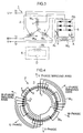
- FIG. 3 shows a circuit diagram of the generator of the invention
- Fig. 4 shows slots in the stator of the generator
- Fig. 5 shows slots in the rotor of the generator.
- a circuit structure of the stator 2 is first explained.
- Three-phase primary generating windings W U , W V , W W of four (4) poles are wound, with phase differences of 120° in the electric angle being provided, on forty eight (48) slots 4 provided in the stator core 3 with regular intervals in such a way that each of the three-phase primary generating windings is wound with a distributed full-pitch winding structure on three slots (in each pole each phase) so that the spatial higher harmonic components of the armature reaction magnetic fields by the three-phase primary generating windings are produced appropriately, and the stator excitation windings W e of twelve (12) poles which are three (odd number) times the number of poles of the primary generating windings are wound on the slots 4 with a concentrated full-pitch winding structure.
- the stator excitation windings W e are connected to the center taps u, v, w of the three-phase primary generating windings W U , W V , W W through the control rectifier means 5.
- the control rectifier means 5 is formed by three-phase full-wave rectifier diodes RD and the variable resistor R r . This control rectifier means 5 is arranged outside the generator.
- the winding structure of the three-phase primary generating windings is not limitative to the distributed full-pitch windings as in this embodiment so long as they can produce appropriate odd-order spatial higher harmonic components of the armature reaction magnetic fields which are usable for the series excitation effects of the field systems.
- the three-phase full-wave rectifier means are constituted by controllable semiconductor devices such as thyristors, the variable resistor R r is not necessary.
- the six field windings W f1 , W f2 , W f3 , W f4 , W f5 and W f6 are respectively short-circuited by the diodes D1, D2, D3, D4, D5 and D6.
- stator excitation windings W e there flow DC currents I e which are obtained by full-wave rectifying the induced electromotive forces in the primary generating windings W U , W V , W W by the three-phase full-wave rectifier R D of the control rectifier means 5 connected between the center taps of the primary generating windings W U , W V , W W and the stator excitation windings W e , whereby the static magnetic fields are produced by the stator excitation windings W e .
- the battery (not shown) may be temporarily connected to the stator excitation windings of the rotor 6 in the same manner as in the first embodiment, so that an electromotive force is induced in the field windings of the rotor.
- a half-wave rectified current based on this electromotive force causes the primary magnetic flux to be induced in the rotor.
- the operation thereof is as follows.
- the loads current I x1 , I x2 , I x3 flow out from the primary generating windings W U , W V , W W , and due to these load currents I x1 , I x2 , I x3 the armature reaction magnetic fields produced by the primary generating windings W U , W V , W W increase.
- the spatial higher harmonic components of the armature reaction magnetic fields increase, the respective electromotive forces induced in the field windings W f1 , W f2 , W f3 , W f4 , W f5 , W f6 individually wound at the positions where they are magnetically coupled with the above spatial higher harmonic components increase, and thus the field currents I f1 , I f2 , I f3 , I f4 , I f5 , I f6 flowing in the field windings increase.
- the electromotive forces induced in the primary generating windings increase, so that the variations in the output voltages against the increase in the impedance voltage drop are compensated.
- the increase and decrease in the loads currents I x1 , I x2 , I x3 in accordance with the increase and decrease in the loads results in the increase and decrease in the field current I f1 , I f2 , I f3 , I f4 , I f5 , I f6 of the rotor and, as a result, the electromotive forces induced in the primary generating windings W U , W V , W W increase or decrease, whereby the increase or decrease in the impedance voltage drop in the primary generating windings is compensated. Consequently, the generator 1 generates substantially constant output voltage (flat-compound characteristics) irrespective of the increase or decrease in the loads.
- the spatial fundamental component of the opposite phase of the armature reaction magnetic fields newly produced by the three-phase unbalanced currents in the primary generating windings causes an electromotive force to be induced in each of the plurality of the field windings so that the series excitation effects of the field systems are achieved. Consequently, the decrease in the series excitation effects of the field systems based on the decrease in the spatial higher harmonic components of the armature reaction magnetic fields caused by the three-phase unbalanced currents is compensated, whereby the output voltage of the generator is compensated against the variations in the loads.
- a plurality of field windings W f1 , W f2 , W f3 , W f4 , W f5 , W f6 are wound on the rotor, that is, wound sequentially in a given number of slots 4 provided with regular intervals in the rotor core 3, in such a manner that the individual field windings have the same pole pitch, that is, 180° in the electric angle as that of the primary generating windings W U , W V , W W so as to be magnetically coupled with the spatial fundamental component of the static magnetic fields produced by the stator excitation windings W e (twelve (12) poles in this embodiment).
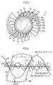
- the distributions of the fundamental and fifth-order harmonic components (lower-order harmonics) among the harmonic components of the armature reaction magnetic fields produced by the primary generating windings, the distributions of the spatial fundamental component of the static magnetic fields produced by the stator excitation windings, and also the arrangement of one field windings among the plurality of the field windings are shown in Fig. 6.
- the function of the rotor, specifically of the field windings wound thereon is explained by showing the electromotive force induced in the field windings of the rotor which is based on the fifth-order spatial higher harmonic components of the armature reaction magnetic fields and also the spatial fundamental component of the static magnetic fields.
- an electromotive force expressed by the above Formula (3) is induced in the field windings W e (C1, C7) and half-wave rectified by the diode D1 (semiconductor rectifier element) connected in series to the field windings W e .
- the rectified DC currents flow in the field windings so that the primary magnetic poles are produced in the rotor.
- all the other odd-order spatial higher harmonic components included respectively in the above Formulas (1) and (2) also cause the electromotive forces to be induced in the field windings which are arranged with 180° pitch in the electric angle, thereby contributing to the formation of the field magnetic poles.
- an electromotive force due to the spatial fundamental component of the opposite phase of the armature reaction magnetic fields is newly added to the field windings.
- An automatic voltage regulator may be connected to the stator excitation windings W e . Further, prior art techniques for DC excitation of the stator can be applied to the generator of the present invention.
- a generator of a second embodiment according to the invention is explained with reference to Figs. 7 and 8.
- Fig. 7 shows a diagram of the three-phase brushless self-excited synchronous generator of the second embodiment
- Fig. 8 shows a structure of slots 12 of a stator 10 of the generator of the second embodiment. Because the rotor in the second embodiment is the same as that shown in Fig. 3 in the above explained first embodiment, both the explanation and illustration thereof are omitted here.
- the structure of the stator 10 is explained.
- Three-phase primary generating windings W U , W V , W W of four (4) poles are wound on forty eight (48) slots provided with regular intervals in a stator core 11 with a phase difference of 120° being provided.
- Each of the three-phase primary windings is wound with three (3) slots (each pole and each phase) with the distributed full-pitch windings so as to appropriately produce the spatial higher harmonic components of the armature reaction magnetic fields.
- Fig. 6 only U-phase primary generating winding W U among the primary generating windings W U , W V , W W is shown.
- a variable reactor 13 is connected to the output terminals U, V, W of the primary generating windings in parallel together with the loads.
- the structure of the three-phase excitation windings is not limitative to the distributed full-pitch windings as in this embodiment so long as they can produce odd-order spatial higher harmonic components of the armature reaction magnetic fields which can be used for attaining the series excitation effects of the field system.
- the circuit structure of the rotor in this embodiment is the same as that of the rotor 6 in the above first embodiment, the detailed explanation of the rotor is omitted here.
- the generated output voltage of the primary generating windings W U , W V , W W is established.
- the variable reactor 13 so as to control the reactor currents I L1 , I L2 , I L3 , the output voltage of the generator 9 at the non-loaded state can be freely controlled.
- the battery B may be temporarily connected to the primary generating windings so that an electromotive force is induced in the field windings of the rotor.
- a half-wave rectified current based on this electromotive force causes the primary magnetic field to be induced in the rotor.
- the spatial higher harmonic components of the armature reaction magnetic fields increase or decrease
- the electromotive forces respectively induced in the field windings W f1 , W f2 , W f3 , W f4 , W f5 , W f6 which are individually wound at the positions where they are magnetically coupled with the spatial higher harmonic components increase or decrease and, thus, the half-wave rectified currents I f1 , I f2 , I f3 , I f4 , I f5 , I f6 in the field windings increase or decrease.
- the induced electromotive forces in the primary generating windings increase or decrease.
- this generator 9 has an automatic voltage regulating (AVR) function in itself which is capable of appropriately responding to the variations in the load power factors.
- the number of slots in the rotor in the first and second embodiments explained above is twenty four (24)
- the number of slots may be twenty (20) so that the plurality of rotor field windings are arranged in the slots in such a way that they are magnetically coupled at the maximum with the fifth-order harmonic component among the odd-order spatial higher harmonic components.
- the field windings are coupled with other odd-order harmonic components than the fifth-order harmonic component, though such coupling is weak.
- the advantages of the present invention are not lost even if the arrangement is such that the field windings are to be magnetically coupled with the spatial higher harmonic component of the specific order.
- the plurality of field windings are arranged on the rotor core so as to be magnetically coupled with the odd-order spatial higher harmonic components.
- the generator according to this embodiment even when three-phase unbalanced or single-phase loads are applied thereto, since the spatial fundamental component of an opposite phase of the armature reaction magnetic fields newly produced by the three-phase unbalanced currents flowing in the primary generating windings causes an electromotive force to be induced in each of the plurality of the field windings and results in the series excitation effects of the field system, the decrease in the series excitation effects of the field system caused by the decrease in the spatial higher harmonic components of the armature reaction magnetic fields by the three-phase unbalanced currents is compensated. Consequently, the output voltage of the generator is kept constant against the variations in the loads.
- the rotor excitation windings becomes unnecessary which have been indispensable in the prior art generators.
- the rotor can be constructed in simple and rigid by the rotor field windings and the semiconductor rectifier means.
- the time constant of the rotor circuit becomes small due to the elimination of the rotor excitation windings, so that the response speed of the controlling of the output voltage becomes fast.
- the rotor is so constructed that it is magnetically coupled with the odd-order harmonic components of both the armature reaction field magnetic fields and the static magnetic fields, in any case where three-phase balanced loads, three-phase unbalanced loads or single-phase loads are connected to the generator, the series excitation effects can be further enhanced, whereby the output voltage of the generator can be more effectively compensated against the variations in the loads.
Landscapes
- Engineering & Computer Science (AREA)
- Power Engineering (AREA)
- Synchronous Machinery (AREA)
- Control Of Eletrric Generators (AREA)
Applications Claiming Priority (2)
| Application Number | Priority Date | Filing Date | Title |
|---|---|---|---|
| JP212044/94 | 1994-08-11 | ||
| JP21204494A JP3489105B2 (ja) | 1994-08-11 | 1994-08-11 | ブラシレス自励三相同期発電機 |
Publications (3)
| Publication Number | Publication Date |
|---|---|
| EP0696834A2 true EP0696834A2 (fr) | 1996-02-14 |
| EP0696834A3 EP0696834A3 (fr) | 1996-05-01 |
| EP0696834B1 EP0696834B1 (fr) | 1998-03-25 |
Family
ID=16615947
Family Applications (1)
| Application Number | Title | Priority Date | Filing Date |
|---|---|---|---|
| EP95305515A Expired - Lifetime EP0696834B1 (fr) | 1994-08-11 | 1995-08-08 | Génératrice synchrone triphasée et auto-excitée sans balais sans bobinage d'excitation sur le rotor |
Country Status (4)
| Country | Link |
|---|---|
| US (1) | US5598091A (fr) |
| EP (1) | EP0696834B1 (fr) |
| JP (1) | JP3489105B2 (fr) |
| DE (1) | DE69501859T2 (fr) |
Cited By (4)
| Publication number | Priority date | Publication date | Assignee | Title |
|---|---|---|---|---|
| EP0920112A1 (fr) * | 1997-11-28 | 1999-06-02 | Satake Corporation | Génératrice synchrone triphasée sans balais, avec système de champ rotorique renforcé |
| WO2014147181A3 (fr) * | 2013-03-21 | 2015-07-30 | Feaam Gmbh | Machine synchrone |
| EP3509208A1 (fr) * | 2018-01-04 | 2019-07-10 | ABB Schweiz AG | Procédé de commande d'une machine synchrone sans excitateur |
| CN110794195A (zh) * | 2019-11-18 | 2020-02-14 | 北京煜邦电力技术股份有限公司 | 一种三相同步采样方法、装置及存储介质 |
Families Citing this family (13)
| Publication number | Priority date | Publication date | Assignee | Title |
|---|---|---|---|---|
| US6188204B1 (en) * | 1999-08-05 | 2001-02-13 | Joseph Vithayathil | Brushless AC field system for stable frequency variable speed alternators |
| JP2002218798A (ja) * | 2001-01-22 | 2002-08-02 | Mitsubishi Electric Corp | 車両用電源装置 |
| JP4789030B2 (ja) * | 2001-04-27 | 2011-10-05 | 財団法人北九州産業学術推進機構 | 可変リアクトルを用いた誘導発電機の電圧制御方法 |
| US6857179B2 (en) * | 2001-09-28 | 2005-02-22 | Reliance Electric Technologies, Llc | Method for making an electric motor stator |
| JP2003134766A (ja) * | 2001-10-26 | 2003-05-09 | Denso Corp | ブラシレス回転電機 |
| DE10153644C2 (de) * | 2001-10-31 | 2003-11-20 | Aloys Wobben | Windenergieanlage mit berührungsloser Energieübertragung auf den Rotor |
| US20040164695A1 (en) * | 2003-02-26 | 2004-08-26 | William M. Hallidy | Electrodynamic machines and components therefor and methods of making and using same |
| US20040164701A1 (en) * | 2003-02-26 | 2004-08-26 | William Hallidy | Electrodynamic machines and components therefor and methods of making and using same |
| WO2008061312A1 (fr) * | 2006-11-22 | 2008-05-29 | Synectic Engineering Pty Limited | Appareil de soudage portable et alternateur |
| JP5302527B2 (ja) | 2007-10-29 | 2013-10-02 | 株式会社豊田中央研究所 | 回転電機及びその駆動制御装置 |
| JP2009112169A (ja) * | 2007-10-31 | 2009-05-21 | Honda Motor Co Ltd | 発電機の出力制御装置 |
| US10075051B2 (en) * | 2015-03-16 | 2018-09-11 | Foster-Miller, Inc. | Series-wound heteropolar inductor motor |
| WO2025158464A1 (fr) * | 2024-01-24 | 2025-07-31 | Volektra India Private Limited | Machine synchrone à excitation interne sans aimant et sans balai |
Citations (2)
| Publication number | Priority date | Publication date | Assignee | Title |
|---|---|---|---|---|
| JPH03245755A (ja) | 1990-02-23 | 1991-11-01 | Shindaiwa Kogyo Kk | ブラシレス自励同期発電機 |
| JPH04285454A (ja) | 1991-03-11 | 1992-10-09 | Shindaiwa Kogyo Kk | ブラシレス自励同期発電機 |
Family Cites Families (9)
| Publication number | Priority date | Publication date | Assignee | Title |
|---|---|---|---|---|
| DE1563313A1 (de) * | 1966-10-14 | 1969-11-27 | Piller Kg Anton | Erregereinrichtung fuer Synchronmaschinen |
| US3704402A (en) * | 1971-02-17 | 1972-11-28 | Siemens Ag | Speed controlled synchronous inverter motor |
| DE2615117B2 (de) * | 1976-04-07 | 1978-07-20 | Siemens Ag, 1000 Berlin Und 8000 Muenchen | Mit einer Überspannungsschutzanordnung versehener konstantspannungsgeregelter bürstenloser Synchrongenerator |
| AT340523B (de) * | 1976-04-27 | 1977-12-27 | Hitzinger & Co Dipl Ing | Burstenloser synchrongenerator |
| US4246532A (en) * | 1978-06-07 | 1981-01-20 | Kokusan Denki Co., Ltd. | Synchronous generator |
| JPS61288755A (ja) * | 1985-06-12 | 1986-12-18 | Fukuo Shibata | 回転電気機械の構造 |
| US4851758A (en) * | 1987-03-09 | 1989-07-25 | Sawafuji Electric Co., Ltd. | Brushless generator |
| US5239254A (en) * | 1992-03-26 | 1993-08-24 | Shindaiwa Kogyo Company Ltd. | Series-exciting device for synchronous generators |
| US5532574A (en) * | 1994-03-28 | 1996-07-02 | Westinghouse Electric Corporation | Brushless exciter protection circuit |
-
1994
- 1994-08-11 JP JP21204494A patent/JP3489105B2/ja not_active Expired - Fee Related
-
1995
- 1995-08-08 DE DE69501859T patent/DE69501859T2/de not_active Expired - Fee Related
- 1995-08-08 EP EP95305515A patent/EP0696834B1/fr not_active Expired - Lifetime
- 1995-08-10 US US08/513,526 patent/US5598091A/en not_active Expired - Fee Related
Patent Citations (2)
| Publication number | Priority date | Publication date | Assignee | Title |
|---|---|---|---|---|
| JPH03245755A (ja) | 1990-02-23 | 1991-11-01 | Shindaiwa Kogyo Kk | ブラシレス自励同期発電機 |
| JPH04285454A (ja) | 1991-03-11 | 1992-10-09 | Shindaiwa Kogyo Kk | ブラシレス自励同期発電機 |
Cited By (6)
| Publication number | Priority date | Publication date | Assignee | Title |
|---|---|---|---|---|
| EP0920112A1 (fr) * | 1997-11-28 | 1999-06-02 | Satake Corporation | Génératrice synchrone triphasée sans balais, avec système de champ rotorique renforcé |
| US6130492A (en) * | 1997-11-28 | 2000-10-10 | Satake Corporation | Brushless three-phase synchronous generator having enhanced rotor field system |
| WO2014147181A3 (fr) * | 2013-03-21 | 2015-07-30 | Feaam Gmbh | Machine synchrone |
| CN105164903A (zh) * | 2013-03-21 | 2015-12-16 | 菲艾姆股份有限公司 | 同步电机 |
| EP3509208A1 (fr) * | 2018-01-04 | 2019-07-10 | ABB Schweiz AG | Procédé de commande d'une machine synchrone sans excitateur |
| CN110794195A (zh) * | 2019-11-18 | 2020-02-14 | 北京煜邦电力技术股份有限公司 | 一种三相同步采样方法、装置及存储介质 |
Also Published As
| Publication number | Publication date |
|---|---|
| JP3489105B2 (ja) | 2004-01-19 |
| EP0696834B1 (fr) | 1998-03-25 |
| DE69501859T2 (de) | 1998-09-17 |
| US5598091A (en) | 1997-01-28 |
| DE69501859D1 (de) | 1998-04-30 |
| EP0696834A3 (fr) | 1996-05-01 |
| JPH0865976A (ja) | 1996-03-08 |
Similar Documents
| Publication | Publication Date | Title |
|---|---|---|
| US5694027A (en) | Three-phase brushless self-excited synchronous generator with no rotor excitation windings | |
| EP0696834B1 (fr) | Génératrice synchrone triphasée et auto-excitée sans balais sans bobinage d'excitation sur le rotor | |
| US4625160A (en) | Variable speed constant frequency generating system | |
| US8085004B2 (en) | Generator with quadrature AC excitation | |
| US3768002A (en) | Generator excitation system with rotating electromagnetic energy connector and internal winding power source | |
| US5559385A (en) | Stator of ac electric machine | |
| US4786853A (en) | Brushless capacitor excited generator | |
| CN1118921C (zh) | 带增强转子场系的无电刷三相同步发电机 | |
| US3551767A (en) | Electric control system for induction machine containing winding elements of two wound rotor induction machines | |
| US3210644A (en) | Dynamo electric machine | |
| US4656410A (en) | Construction of single-phase electric rotating machine | |
| US3461368A (en) | Diode controlled exciter circuit for synchronous motors | |
| CN1042631A (zh) | 带有电压和电流调节的电势源激磁系统 | |
| US5731971A (en) | Apparatus for providing multiple, phase-shifted power outputs | |
| JP2887686B2 (ja) | ブラシレス自励同期発電機 | |
| JPH077999A (ja) | 交流発電機 | |
| JP3489108B2 (ja) | ブラシレス自励単相同期発電機 | |
| GB2071430A (en) | Brushless A.C. Generators | |
| EP0266003A2 (fr) | Alternateurs compounds sans-balais | |
| SU710096A1 (ru) | Преобразователь частоты | |
| JPH1155912A (ja) | 円筒型同期発電機 | |
| JPS6223348A (ja) | ブラシレス発電機 | |
| JPH06269151A (ja) | ブラシレス同期発電機 | |
| Chakraborty et al. | Performance of a Doubly Excited Cylindrical Rotor Brushless Synchronous Generator | |
| JP2530297B2 (ja) | 交流発電装置 |
Legal Events
| Date | Code | Title | Description |
|---|---|---|---|
| PUAI | Public reference made under article 153(3) epc to a published international application that has entered the european phase |
Free format text: ORIGINAL CODE: 0009012 |
|
| AK | Designated contracting states |
Kind code of ref document: A2 Designated state(s): CH DE FR GB IT LI NL SE |
|
| PUAL | Search report despatched |
Free format text: ORIGINAL CODE: 0009013 |
|
| AK | Designated contracting states |
Kind code of ref document: A3 Designated state(s): CH DE FR GB IT LI NL SE |
|
| 17P | Request for examination filed |
Effective date: 19960607 |
|
| 17Q | First examination report despatched |
Effective date: 19970129 |
|
| GRAG | Despatch of communication of intention to grant |
Free format text: ORIGINAL CODE: EPIDOS AGRA |
|
| GRAG | Despatch of communication of intention to grant |
Free format text: ORIGINAL CODE: EPIDOS AGRA |
|
| GRAH | Despatch of communication of intention to grant a patent |
Free format text: ORIGINAL CODE: EPIDOS IGRA |
|
| GRAH | Despatch of communication of intention to grant a patent |
Free format text: ORIGINAL CODE: EPIDOS IGRA |
|
| GRAA | (expected) grant |
Free format text: ORIGINAL CODE: 0009210 |
|
| AK | Designated contracting states |
Kind code of ref document: B1 Designated state(s): CH DE FR GB IT LI NL SE |
|
| REG | Reference to a national code |
Ref country code: CH Ref legal event code: EP |
|
| ET | Fr: translation filed | ||
| REF | Corresponds to: |
Ref document number: 69501859 Country of ref document: DE Date of ref document: 19980430 |
|
| REG | Reference to a national code |
Ref country code: CH Ref legal event code: NV Representative=s name: PATENTANWAELTE SCHAAD, BALASS, MENZL & PARTNER AG |
|
| ITF | It: translation for a ep patent filed | ||
| PLBE | No opposition filed within time limit |
Free format text: ORIGINAL CODE: 0009261 |
|
| STAA | Information on the status of an ep patent application or granted ep patent |
Free format text: STATUS: NO OPPOSITION FILED WITHIN TIME LIMIT |
|
| 26N | No opposition filed | ||
| REG | Reference to a national code |
Ref country code: GB Ref legal event code: IF02 |
|
| PGFP | Annual fee paid to national office [announced via postgrant information from national office to epo] |
Ref country code: SE Payment date: 20020806 Year of fee payment: 8 |
|
| PGFP | Annual fee paid to national office [announced via postgrant information from national office to epo] |
Ref country code: CH Payment date: 20020815 Year of fee payment: 8 |
|
| PGFP | Annual fee paid to national office [announced via postgrant information from national office to epo] |
Ref country code: NL Payment date: 20020829 Year of fee payment: 8 |
|
| PG25 | Lapsed in a contracting state [announced via postgrant information from national office to epo] |
Ref country code: SE Free format text: LAPSE BECAUSE OF NON-PAYMENT OF DUE FEES Effective date: 20030809 |
|
| PG25 | Lapsed in a contracting state [announced via postgrant information from national office to epo] |
Ref country code: LI Free format text: LAPSE BECAUSE OF NON-PAYMENT OF DUE FEES Effective date: 20030831 Ref country code: CH Free format text: LAPSE BECAUSE OF NON-PAYMENT OF DUE FEES Effective date: 20030831 |
|
| PG25 | Lapsed in a contracting state [announced via postgrant information from national office to epo] |
Ref country code: NL Free format text: LAPSE BECAUSE OF NON-PAYMENT OF DUE FEES Effective date: 20040301 |
|
| EUG | Se: european patent has lapsed | ||
| REG | Reference to a national code |
Ref country code: CH Ref legal event code: PL |
|
| NLV4 | Nl: lapsed or anulled due to non-payment of the annual fee |
Effective date: 20040301 |
|
| PGFP | Annual fee paid to national office [announced via postgrant information from national office to epo] |
Ref country code: FR Payment date: 20060808 Year of fee payment: 12 |
|
| PGFP | Annual fee paid to national office [announced via postgrant information from national office to epo] |
Ref country code: IT Payment date: 20060831 Year of fee payment: 12 |
|
| PGFP | Annual fee paid to national office [announced via postgrant information from national office to epo] |
Ref country code: DE Payment date: 20070809 Year of fee payment: 13 |
|
| PGFP | Annual fee paid to national office [announced via postgrant information from national office to epo] |
Ref country code: GB Payment date: 20070809 Year of fee payment: 13 |
|
| REG | Reference to a national code |
Ref country code: FR Ref legal event code: ST Effective date: 20080430 |
|
| PG25 | Lapsed in a contracting state [announced via postgrant information from national office to epo] |
Ref country code: FR Free format text: LAPSE BECAUSE OF NON-PAYMENT OF DUE FEES Effective date: 20070831 |
|
| GBPC | Gb: european patent ceased through non-payment of renewal fee |
Effective date: 20080808 |
|
| PG25 | Lapsed in a contracting state [announced via postgrant information from national office to epo] |
Ref country code: DE Free format text: LAPSE BECAUSE OF NON-PAYMENT OF DUE FEES Effective date: 20090303 |
|
| PG25 | Lapsed in a contracting state [announced via postgrant information from national office to epo] |
Ref country code: IT Free format text: LAPSE BECAUSE OF NON-PAYMENT OF DUE FEES Effective date: 20070808 |
|
| PG25 | Lapsed in a contracting state [announced via postgrant information from national office to epo] |
Ref country code: GB Free format text: LAPSE BECAUSE OF NON-PAYMENT OF DUE FEES Effective date: 20080808 |