EP0696867B1 - Farbbildungssystem - Google Patents
Farbbildungssystem Download PDFInfo
- Publication number
- EP0696867B1 EP0696867B1 EP95305554A EP95305554A EP0696867B1 EP 0696867 B1 EP0696867 B1 EP 0696867B1 EP 95305554 A EP95305554 A EP 95305554A EP 95305554 A EP95305554 A EP 95305554A EP 0696867 B1 EP0696867 B1 EP 0696867B1
- Authority
- EP
- European Patent Office
- Prior art keywords
- series
- input
- points
- point
- input points
- Prior art date
- Legal status (The legal status is an assumption and is not a legal conclusion. Google has not performed a legal analysis and makes no representation as to the accuracy of the status listed.)
- Expired - Lifetime
Links
- 238000013507 mapping Methods 0.000 title description 13
- 238000000034 method Methods 0.000 claims description 85
- 230000008569 process Effects 0.000 description 39
- FBOUIAKEJMZPQG-AWNIVKPZSA-N (1E)-1-(2,4-dichlorophenyl)-4,4-dimethyl-2-(1,2,4-triazol-1-yl)pent-1-en-3-ol Chemical compound C1=NC=NN1/C(C(O)C(C)(C)C)=C/C1=CC=C(Cl)C=C1Cl FBOUIAKEJMZPQG-AWNIVKPZSA-N 0.000 description 17
- 238000012546 transfer Methods 0.000 description 15
- 238000006243 chemical reaction Methods 0.000 description 6
- 238000004364 calculation method Methods 0.000 description 5
- 239000000654 additive Substances 0.000 description 1
- 230000000996 additive effect Effects 0.000 description 1
- 238000010923 batch production Methods 0.000 description 1
- 239000003086 colorant Substances 0.000 description 1
- 238000012937 correction Methods 0.000 description 1
- 230000003247 decreasing effect Effects 0.000 description 1
- 230000001419 dependent effect Effects 0.000 description 1
- 238000010586 diagram Methods 0.000 description 1
- 239000000976 ink Substances 0.000 description 1
- 230000003993 interaction Effects 0.000 description 1
- 238000005259 measurement Methods 0.000 description 1
- 238000012986 modification Methods 0.000 description 1
- 230000004048 modification Effects 0.000 description 1
- 230000010355 oscillation Effects 0.000 description 1
- 238000012545 processing Methods 0.000 description 1
- 230000009467 reduction Effects 0.000 description 1
- 238000010561 standard procedure Methods 0.000 description 1
- 238000006467 substitution reaction Methods 0.000 description 1
- 230000009466 transformation Effects 0.000 description 1
Images




Classifications
-
- H—ELECTRICITY
- H04—ELECTRIC COMMUNICATION TECHNIQUE
- H04N—PICTORIAL COMMUNICATION, e.g. TELEVISION
- H04N1/00—Scanning, transmission or reproduction of documents or the like, e.g. facsimile transmission; Details thereof
- H04N1/46—Colour picture communication systems
- H04N1/56—Processing of colour picture signals
- H04N1/60—Colour correction or control
- H04N1/6016—Conversion to subtractive colour signals
- H04N1/6019—Conversion to subtractive colour signals using look-up tables
-
- H—ELECTRICITY
- H04—ELECTRIC COMMUNICATION TECHNIQUE
- H04N—PICTORIAL COMMUNICATION, e.g. TELEVISION
- H04N1/00—Scanning, transmission or reproduction of documents or the like, e.g. facsimile transmission; Details thereof
- H04N1/46—Colour picture communication systems
- H04N1/56—Processing of colour picture signals
- H04N1/60—Colour correction or control
- H04N1/6058—Reduction of colour to a range of reproducible colours, e.g. to ink- reproducible colour gamut
Definitions
- the present invention relates to the curve fitting of a series of data points and has particular applications to curved fittings so as to produce suitable color look up tables for a color space re-mapping process.
- Such a color re-mapping process finds particular application in the re-calibration of color printing and scanning devices.
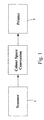
- Fig. 1 there is shown a simplified form of a prior art color copying process.
- an image which is to be copied is placed on a scanner 1 and scanned at a high resolution, commonly 600 dots per inch (dpi).
- the scanned values produced for each pixel of the image on scanner 1 includes separate values for the Red, Green and Blue (RGB) color components.
- RGB Red, Green and Blue
- the scanned pixels can be plotted in a three dimensional RGB color space, also known as an additive color space.
- the scanned pixels are normally printed out on a printer 2, which normally prints an image by utilising multiple color passes.
- the printer 2 normally works in a subtractive color space such as a Cyan, Magenta and Yellow (CYM) color space, or a Cyan, Yellow, Magenta and blacK (CYMK) color space.
- CYM Cyan, Magenta and Yellow
- CYMK Cyan, Yellow, Magenta and blacK
- RGB - CYMK transfer function In order to determine the mapping for any particular RGB - CYMK transfer function, a series of known RGB values can be printed out by the output device or printer 2 and their colormetric CYMK values can be measured using a colorimeter.
- one method of determining a transfer function is to measure the color component values of a predetermined number of points and to derive a table with each entry being a 7 tuple (RGBCYMK) comprising the RGB values and corresponding CYMK values obtained from measurements. Points not in the table can then be derived by means of interpolation.
- the normal interpolation technique used is linear interpolation and an example of such a system is given in US Patent No. 3,893,166 by Pugsley, entitled "Color Correcting Image Reproduction Methods and Apparatus".
- the predetermined points can be chosen utilising a number of criteria. Firstly, it is desirable that the points cover the whole of the color space. Secondly, the system utilised for interpolation can require the predetermined points to be, for example, evenly spaced within one or other of the color spaces. Alternatively, it can be desirable to increase the number of points where the color transfer function is not well behaved, at the expense of decreasing the number of points where the transfer function is well behaved, thereby giving an overall increase in accuracy for the interpolation process.
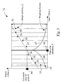
- Fig. 2 shows a single slice through the multi-dimensional plane for constant green and blue for illustration of a particular transfer function between the Red component of an input image and the required Magenta output component.
- Lagrange interpolation a polynomial 9 is fitted to the sample data such that it passes through each of the sample data points.
- Use of Lagrange interpolation often produces inadequate results for those sample points which are not well behaved (i.e. do not substantially conform to a linear relationship) and the Lagrange interpolation can result in a transfer function having excessive oscillation thereby producing unrealistic results.
- a second known method is that known as "least squares" which, in its simplest form, fits a straight line, 10, in the vicinity of the given data points such that the sum of the squares of the distances of those points from the straight line is minimised, where the distance is measured in the vertical direction.
- the least squares method can itself lead to a substantial reduction in the fidelity of the transfer function as much detail is lost.
- the fitting of quadratics and higher order polynomials utilising a least squared methodology is also known to those skilled in the art but goes only part of the way to solving this problem of fidelity loss.
- a "least squares" algorithm is disclosed in US-A-4 992 861 (EASTMAN KODAK Co.)
- a third method of deriving the transfer function can consist of constructing straight line segments between the various data points.
- this method can lead to large discontinuities of derivatives at the various end points.
- such a transfer function has been found to produce unacceptable results with banding and other artifacts being found in certain images.
- a method for computing the output values of a first series of input points, given the output values of a second series of input points comprising, for each of said first series of input points: forming a weighted distance measure, for each of said second series of input points, derived from the absolute distance between said first series input point and said second series input point; determining an error measure function including a summation over each of said second series of input points, of an absolute error between a proposed line or curve and the output value of said second series of points, weighted by said weighted distance measure; substantially minimizing said error function to produce a finalized line or curve; and, utilizing said finalized line or curve to derive an output value at said first series point.
- said step of determining said error measure function comprises determining said summation from a previously calculated summation forming part of said error measure functions for adjacent input points of a current one of said first series of input points and from said second series of input points which are between said adjacent input points and said current one of said first series of input points.
- said step of determining said error measure function further comprises multiplying said previously calculated summation by a constant.
- the transfer function is determined by utilising a "weighted least squares" process, the details of which will be further described herein, firstly in relation to the a one dimensional transfer process and subsequently in relation to a multi-dimensional transfer process.
- a weighting (w i ) which is assigned to each sample point 20-28 depending on how close it is to a desired value e.g. 12.
- d represents an absolute distance measure between the sample point
- ⁇ is a scaling or noise following factor. Larger values of ⁇ result in the closer points having substantially more influence on the resultant output value. In the preferred embodiment the value used for ⁇ is 0.06 when the color values take on the range 0 to 1.
- E the partial derivatives of E are taken and set to zero as follows: i.e. i.e.
- each desired output point is calculated in the following manner:
- a weighting (w i ) is assigned to each sample point depending on how close it is to the desired output point, with the distance being calculated using a Euclidean distance measure.
- V ax + by + cz + d is the equation of a hyperplane which approximates the data points in the four dimensional space.
- the obtained points can then be loaded into a color correction system such as that disclosed in US Patent No. 3,893,166 and utilised in an interpolation system for deriving color space transformation values.
- weighting function such as a Gaussian or a linear distance measure can be used, however, the stated weighting function has been found to produce the best results to date.
- An example weighting function which is somewhat quicker to evaluate on modern computers and which also gives suitable results and which can be used in substitution for Equation 1 is: e -(
- the one dimensional case of the problem can be described as the calculation of a mapping of a one-dimensional array of equally-spaced point-values from a randomly distributed set of point-values utilising the previously described "exponential" least squares fit to calculate each equally spaced point-value.
- Fig. 3 there is shown a second example of an input - output mapping utilising a single weighting function.
- the weighting function 51 is illustrated in the one dimensional case. It is assumed that eleven sample points 52 - 61 are provided and it is desired to calculate the output value Q 64 at the desired point X, 62 in accordance with the previously described weighted exponential method with reference to Equation 1.
- the "exponential" least squares fit involves a weighted summation of quantities from the sample input values.
- an example of the resultant summation can be characterised as: sum i (w(x i ) * x i ) or sum i (w(y i ) * y i ) where (x i , y i ) is the position of sample point i, sum i is the sum over all the sample values and w(x) is the desired weighting function.
- the sample points closer to the desired point 65 are more important, so they have a greater weight attached to them when summing.
- Fig. 4 there is shown the weighting function of Fig. 3 when applied to a series of equally spaced input points.
- the weighting function can be said to "move” from left to right. This is illustrated in Fig. 4 where the weighting function takes the same form around each of the desired input points X 1 to X N .
- the sums S left and S right can be calculated independently.
- the sum S left can be calculated for the left hand side points in accordance with the following pseudo-code:
- S left (X j ) is in the form of a recurrence relation involving the previous sum S left (X j-1 ) and those values between a previous input point and a current input point.
- the process of calculating S right can be determined in a similar manner, moving right-to-left instead of left-to-right.
- Fig. 5 there is shown the process of calculating a new output point in accordance with the recurrence relationship utilised as part of a second embodiment.
- the value of the previous sum, calculated for the point 81 is known. Therefore, in order to move from the point 81 to the point 80, the previous sum for the point 81 is multiplied by the constant e -K / ⁇ and added to the weighted value of any sample point e.g. 82, which is between the points 80 and 81, to produce the new sum.
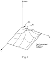
- Fig. 6 there is shown the weighting function of Fig. 3 in two dimensions.
- the weighting function is inherently a three dimensional process (w(x,y,z)), however, due to the difficulties of illustrating a three dimensional process, only two dimensions (w(x,y)) are illustrated in Fig. 6.
- any movement of the weighting function in the direction of constant y in the direction of arrow 86), can be simulated by the multiplication of the relevant sums by a constant.
- S(X,Y,Z) sum i (w X,Y,Z (x i ,y i ,z i ) * v i )
- the weighting function can be split into a "left hand side” and a "right hand side”:
- S left (X,Y,Z) sum i:xi ⁇ X (w X,Y,Z (x i ,y i ,z i ) * v i )
- S(X,Y,Z) S left (X,Y,Z) + S right (X,Y,Z)
- the sums S left and S right can then be calculated independently.
- the sum S left is calculated at all points as follows:
- the final result is in the same form as the one dimensional case.
- the above three dimensional incremental process can be further improved on from an order O(N 2 ) process to a process requiring order O(1) passes through a set of three dimensional input data at the expense of requiring O(N 3 ) storage locations, which is practical for most applications.
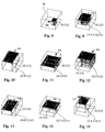
- the region W (91) can be made up from a number of sub-regions or sub-volumes.
- Fig. 8 to Fig. 15 there is shown a number of sub-regions VO - V7.
- These regions include: V0 (Fig. 8) which is the rectangle bounded by the points (X-K, Y-K, Z-K) and (X,Y,Z)
- V1 (Fig. 9) which is the rectangle bounded by the points (0,0,0) and (X-K, Y-K, Z-K).
- V2 (Fig. 10) which is the rectangle bounded by the points (0,0,0) and (X-K, Y, Z).
- V3 (Fig.
- V4 which is the rectangle bounded by the points (0,0,0) and (X, Y, Z-K).
- V5 (Fig. 13) which is the rectangle bounded by the points (0,0,0) and (X-K, Y, Z-K).
- V6 (Fig. 14) which is the rectangle bounded by the points (0,0,0) and (X, Y-K, Z-K).
- V7 (Fig. 15) which is the rectangle bounded by the points (0,0,0) and (X-K, Y-K, Z).
- Equation 27 The other summations of Equation 27 to Equation 34 can then be calculated in a similar manner.
- Equation 35 can be utilised to produce a value of S ⁇ ⁇ ⁇ (X,Y,Z) for each desired output point.
- the first method least-squares operation requires O(N 3 ) passes through the data.
- execution time for the standard method was found to be approximately 30 minutes.
- the basic incremental method was found to take 4 minutes and the fully three-dimensional incremental method was found to take 15 seconds. The times being measured on an unloaded SUN SPARC station IPX.
- Appendix A attached discloses the 'C' code implementation of the final fully three-dimensional incremental method described above.
- the invention can be implemented as mentioned above in a general purpose computing apparatus, or by dedicated hardware or software within an image processing apparatus such as a printer or scanner.
- the invention may be supplied in the form of programs recorded on suitable recording media.
Landscapes
- Engineering & Computer Science (AREA)
- Multimedia (AREA)
- Signal Processing (AREA)
- Image Processing (AREA)
- Facsimile Image Signal Circuits (AREA)
- Color, Gradation (AREA)
- Complex Calculations (AREA)
- Image Analysis (AREA)
- Color Image Communication Systems (AREA)
Claims (26)
- Verfahren zur Erzeugung eines Ausgangssignals, das anzeigbare Ausgangswerte einer ersten Folge von Eingangspunkten in einem ersten Farbraum darstellt, wobei die Ausgangswerte einer zweiten Folge von Eingangspunkten in einem zweiten Farbraum gegeben sind, mit den Schritten für jeden Eingangspunkt der ersten FolgeBilden eines gewichteten Distanzmaßes für jeden Eingangspunkt der zweiten Folge, das aus der absoluten Distanz zwischen dem Eingangspunkt der ersten Folge und dem Eingangspunkt der zweiten Folge hergeleitet wird,Bestimmen einer Fehlermaßfunktion, was eine Summation eines absoluten Fehlers zwischen einer vorgeschlagenen Linie oder Kurve und dem Ausgangswert der durch das gewichtete Distanzmaß gewichteten Punkte der zweiten Folge über jeden Eingangspunkt der zweiten Folge einschließt,wesentliches Minimieren der Fehlermaßfunktion zur Erzeugung einer endgültigen Linie oder Kurve undVerwenden der endgültigen Linie oder Kurve zum Herleiten eines Ausgangswerts an dem Punkt der ersten Folge, wobei der Ausgangswert zur Erzeugung des Ausgangssignals verwendet wird.
- Verfahren nach Anspruch 1, wobei das gewichtete Distanzmaß eine negative Exponentialfunktion eines absoluten Distanzmaßes zwischen dem Punkt der ersten Folge und dem Punkt der zweiten Folge umfasst.
- Verfahren nach Anspruch 2, wobei das gewichtete Distanzmaß die Form
- Verfahren nach Anspruch 3, wobei σ den Wert 0,06 hat.
- Verfahren nach einem der vorhergehenden Ansprüche, wobei die Fehlermaßfunktion das Quadrat des absoluten Fehlers zwischen der vorgeschlagenen Linie oder Kurve und den Ausgangswerten der Punkte der zweiten Folge umfasst.
- Verfahren nach einem der vorhergehenden Ansprüche, wobei beide Punktfolgen dreidimensionale Werte umfassen.
- Verfahren nach Anspruch 6, wobei die dreidimensionalen Werte Werte in einem Rot-, Grün und Blau-Farbraum sind und die Ausgangswerte aus der Gruppe Cyan, Magenta, Gelb oder Schwarz stammen.
- Verfahren nach Anspruch 2, wobei die negative Exponentialfunktion im wesentlichen die Form
- Verfahren nach Anspruch 1 oder 2, wobei der Schritt zur Bestimmung der Fehlermaßfunktion das Bestimmen der Summation aus einer zuvor berechneten Summation, die einen Teil der Fehlermaßfunktionen für angrenzende Eingangspunkte eines aktuellen Eingangspunkts der ersten Folge bildet, und aus den Eingangspunkten der zweiten Folge umfasst, die zwischen den angrenzenden Eingangspunkten und dem aktuellen Eingangspunkt der ersten Folge liegen.
- Verfahren nach Anspruch 9, wobei der Schritt zur Bestimmung der Fehlermaßfunktion ferner ein Multiplizieren der zuvor berechneten Summation mit einer Konstanten umfasst.
- Verfahren nach Anspruch 1, wobei die erste Eingangspunktfolge beabstandete Eingangspunkte und die zweite Eingangspunktfolge Abtastpunkte umfasst, wobei die Summation eine Summation der beabstandeten Eingangspunkte umfasst, und wobei das Verfahren für jeden beabstandeten Eingangspunkt ferner das Bilden einer Summation der beabstandeten Eingangspunkte mit den Schritten umfasst:(A) Berechnen einer Folge endgültiger Oktantsummen mit den Schritten(1) Verwenden jedes beabstandeten Eingangspunkts durch Durchführung der Schritte(i) Bilden einer ersten Folge von Volumina mit acht Ecken, wobei jede Ecke einen angrenzenden beabstandeten Eingangspunkt aufweist,(ii) Bilden einer Folge von als gsum-Werte bezeichneten Werten, die bezüglich ihrer Anzahl der ersten Folge entsprechen und jeweils anfangs Null sind,(2) Bestimmen einer endgültigen Oktantsummation für jeden der acht Volumenoktante um einen gegebenen Abtastpunkt mit den Schritten(i) Durchführen der folgenden Schritte für jeden Abtastpunkt:(a) Bestimmen eines entsprechenden Volumens der Volumenfolge für den Abtastpunkt,(b) Addieren eines gewichteten Werts mal dem Ausgangswert des Abtastpunkts zu dem entsprechenden gsum-Wert, wobei die Gewichtung bezüglich eines Distanzmaßes von einer bestimmten Ecke des entsprechenden Volumens vorgenommen wird, und wobei die Bestimmung bezüglich eines aktuellen Volumenoktanten für jeden der acht Volumenoktanten durchgeführt wird,(ii) Durchführen der folgenden Schritte für jeden gleich beabstandeten Eingangspunkt:
(a) Bilden einer aktuellen Summe der endgültigen Oktantsummen aus den gsum-Werten und gewichteten endgültigen Oktantsummen zuvor berechneter endgültiger Oktantsummen in einer vorbestimmten Reihenfolge,(B) Bilden der Summation der beabstandeten Eingangspunkte aus den Teilsummen des aktuellen gleich beabstandeten Einganspunkts. - Verfahren nach Anspruch 11, wobei die beabstandeten Eingangspunkte in einem Eingangsraum gleich beabstandet sind.
- Verfahren nach Anspruch 12, wobei die Summation O(1) Durchläufe über die zweite Eingangspunktfolge erfordert.
- Verfahren zur Farbumwandlung eines Eingangssignals in einem ersten Farbraum in ein Ausgangssignal in einem zweiten Farbraum, das das Herleiten einer Farbtabelle gemäß dem in einem der Ansprüche 1 bis 13 definierten Verfahren umfasst.
- Verfahren zur Kalibrierung einer Farbdruckvorrichtung, das das in einem der Ansprüche 1 bis 14 definierte Verfahren umfasst.
- Vorrichtung zur Erzeugung eines Ausgangssignals, das anzeigbare Ausgangswerte einer ersten Folge von Eingangspunkten in einem ersten Farbraum darstellt, wobei die Ausgangswerte einer zweiten Folge von Eingangspunkten in einem zweiten Farbraum gegeben sind, miteiner Einrichtung zum Bilden eines gewichteten Distanzmaßes für jeden Eingangspunkt der zweiten Folge, das aus der absoluten Distanz zwischen dem Eingangspunkt der ersten Folge und dem Eingangspunkt der zweiten Folge hergeleitet wird,einer Einrichtung zum Bestimmen einer Fehlerfunktion, was eine Summation über jeden mit dem gewichteten Distanzmaß gewichteten Eingangspunkt der zweiten Folge einschließt,einer Einrichtung zum wesentlichen Minimieren der Fehlermaßfunktion zur Erzeugung einer endgültigen Linie oder Kurve undeiner Einrichtung zum Verwenden der endgültigen Linie oder Kurve zum Herleiten eines Ausgangswerts an dem Punkt der ersten Folge, wobei der Ausgangswert zur Erzeugung des Ausgangssignals verwendet wird.
- Vorrichtung nach Anspruch 16, wobei die Einrichtung zum Bilden der gewichteten Distanzfunktion eine negative Exponentialfunktion eines absoluten Maßes zwischen dem Punkt der ersten Folge und dem Punkt der zweiten Folge verwendet.
- Vorrichtung nach Anspruch 17, wobei das gewichtete Distanzmaß die Form
- Vorrichtung nach Anspruch 18, wobei σ den Wert 0,06 hat.
- Vorrichtung nach einem der Ansprüche 16 bis 19, wobei die Einrichtung zum Bestimmen der Fehlermaßfunktion eine Einrichtung zum Erzeugen des Quadrats des absoluten Fehlers zwischen der vorgeschlagenen Linie oder Kurve und den Ausgangswerten der Punkte der zweiten Folge umfasst.
- Vorrichtung nach einem der Ansprüche 16 bis 20, wobei beide Punktfolgen dreidimensionale Werte umfassen.
- Vorrichtung nach Anspruch 17, wobei die negative Exponentialfunktion im wesentlichen die Form
- Vorrichtung nach Anspruch 16 oder 17, wobei die Einrichtung zum Bestimmen der Fehlermaßfunktion ferner eine Einrichtung zum Bestimmen der Summation aus einer zuvor berechneten Summation, die einen Teil der Fehlermaßfunktionen für angrenzende Eingangspunkte eines aktuellen Eingangspunkts der ersten Folge bildet, und aus den Eingangspunkten der zweiten Folge umfasst, die zwischen den angrenzenden Eingangspunkten und dem aktuellen Eingangspunkt der ersten Folge liegen.
- Vorrichtung nach Anspruch 16, wobei die erste Eingangspunktfolge beabstandete Eingangspunkte und die zweite Eingangspunktfolge Abtastpunkte umfasst, ferner miteiner Einrichtung zum Bilden einer Summation der beabstandeten Eingangspunkte für jeden beabstandeten Eingangspunkt, wobei die Einrichtung zum Bilden umfasst:eine Einrichtung zum Berechnen einer Folge endgültiger Oktantsummen, wobei die Berechnungseinrichtung angepasst ist(i) zum Verwenden jedes beabstandeten Eingangspunkts zur Bildung einer ersten Folge von Volumina mit acht Ecken, wobei jede Ecke einen angrenzenden beabstandeten Eingangspunkt aufweist,(ii) zum Bilden einer Folge von als gsum-Werte bezeichneten Werten, die bezüglich ihrer Anzahl der ersten Folge entsprechen und jeweils anfangs Null sind, und(iii) zum Bestimmen einer endgültigen Oktantsummation für jeden der acht Volumenoktanten um einen gegebenen Abtastpunkt.
- Vorrichtung nach Anspruch 24, wobei die Berechnungseinrichtung zum Bestimmen eines entsprechenden Volumens der Volumenfolge für jeden Abtastpunkt angepasst ist.
- Speichermedium zur Speicherung maschinenlesbarer Anweisungen zur Veranlassung eines Prozessors zur Erzeugung eines Ausgangssignals, das anzeigbare Ausgangswerte einer ersten Folge von Eingangspunkten in einem ersten Farbraum darstellt, mit den SchrittenBilden eines gewichteten Distanzmaßes für jeden Eingangspunkt der zweiten Folge, das aus der absoluten Distanz zwischen dem Eingangspunkt der ersten Folge und dem Eingangspunkt der zweiten Folge hergeleitet wird,Bestimmen einer Fehlermaßfunktion, was eine Summation eines absoluten Fehlers zwischen einer vorgeschlagenen Linie oder Kurve und dem Ausgangswert der durch das gewichtete Distanzmaß gewichteten Punkte der zweiten Folge über jeden Eingangspunkt der zweiten Folge einschließt,wesentliches Minimieren der Fehlermaßfunktion zur Erzeugung einer endgültigen Linie oder Kurve undVerwenden der endgültigen Linie oder Kurve zum Herleiten eines Ausgangswerts an dem Punkt der ersten Folge, wobei der Ausgangswert zur Erzeugung des Ausgangssignals verwendet wird.
Applications Claiming Priority (9)
| Application Number | Priority Date | Filing Date | Title |
|---|---|---|---|
| AUPM7411A AUPM741194A0 (en) | 1994-08-11 | 1994-08-11 | Colour mapping system |
| AUPM7411/94 | 1994-08-11 | ||
| AUPM741194 | 1994-08-11 | ||
| AUPN195195 | 1995-03-24 | ||
| AUPN1951A AUPN195195A0 (en) | 1995-03-24 | 1995-03-24 | Colour mapping system |
| AUPN1951/95 | 1995-03-24 | ||
| AUPN394995 | 1995-07-03 | ||
| AUPN3949/95 | 1995-07-03 | ||
| AUPN3949A AUPN394995A0 (en) | 1995-07-03 | 1995-07-03 | Colour mapping system |
Publications (3)
| Publication Number | Publication Date |
|---|---|
| EP0696867A2 EP0696867A2 (de) | 1996-02-14 |
| EP0696867A3 EP0696867A3 (de) | 1996-07-10 |
| EP0696867B1 true EP0696867B1 (de) | 2000-03-01 |
Family
ID=27157802
Family Applications (1)
| Application Number | Title | Priority Date | Filing Date |
|---|---|---|---|
| EP95305554A Expired - Lifetime EP0696867B1 (de) | 1994-08-11 | 1995-08-09 | Farbbildungssystem |
Country Status (4)
| Country | Link |
|---|---|
| US (1) | US5880738A (de) |
| EP (1) | EP0696867B1 (de) |
| JP (1) | JPH08106529A (de) |
| DE (1) | DE69515230T2 (de) |
Cited By (3)
| Publication number | Priority date | Publication date | Assignee | Title |
|---|---|---|---|---|
| US7545499B2 (en) | 2005-04-12 | 2009-06-09 | X-Rite, Inc. | Systems and methods for measuring a colored flexible material during a manufacturing process |
| US7557924B2 (en) | 2005-08-15 | 2009-07-07 | X-Rite, Inc. | Apparatus and methods for facilitating calibration of an optical instrument |
| US7557925B2 (en) | 2005-08-15 | 2009-07-07 | X-Rite, Inc. | Optical instrument and parts thereof for optimally defining light pathways |
Families Citing this family (14)
| Publication number | Priority date | Publication date | Assignee | Title |
|---|---|---|---|---|
| US7382379B1 (en) | 1997-06-27 | 2008-06-03 | Eastman Kodak Company | Arrangement for mapping colors between imaging systems and method thereof |
| US6362808B1 (en) | 1997-07-03 | 2002-03-26 | Minnesota Mining And Manufacturing Company | Arrangement for mapping colors between imaging systems and method therefor |
| JP4067609B2 (ja) * | 1997-09-26 | 2008-03-26 | 富士通株式会社 | 色信号選択装置、色信号補間装置、色信号生成装置、包囲点選択方法及び色変換テーブルの作成方法 |
| US7030888B1 (en) * | 1999-03-01 | 2006-04-18 | Eastman Kodak Company | Color processing |
| US7009734B2 (en) * | 2000-08-22 | 2006-03-07 | Canon Kabushiki Kaisha | Method and apparatus for forming color transform lookup table, and image processing method |
| US6621498B1 (en) * | 2000-11-01 | 2003-09-16 | Xerox Corporation | High-speed non-separable color table lookup |
| US6539323B2 (en) | 2001-05-04 | 2003-03-25 | Electronics For Imaging, Inc. | Methods and apparatus for correcting spectral color measurements |
| US6584435B2 (en) * | 2001-08-30 | 2003-06-24 | Xerox Corporation | Systems and methods for determining spectra using dynamic karhunen-loeve algorithms with measurements from led color sensor |
| US6721692B2 (en) * | 2001-08-30 | 2004-04-13 | Xerox Corporation | Systems and methods for determining spectra using dynamic least squares algorithms with measurements from LED color sensor |
| US7016884B2 (en) * | 2002-06-27 | 2006-03-21 | Microsoft Corporation | Probability estimate for K-nearest neighbor |
| US7505171B2 (en) * | 2003-08-27 | 2009-03-17 | Xerox Corporation | Full user-intent color data stream imaging methods and systems |
| US7616342B2 (en) * | 2004-12-03 | 2009-11-10 | Xerox Corporation | Mechanism for allowing content-independent imaging date stream object usage |
| US7301627B2 (en) | 2005-04-05 | 2007-11-27 | X-Rite, Inc. | Systems and methods for monitoring a process output with a highly abridged spectrophotometer |
| US20070002180A1 (en) * | 2005-06-30 | 2007-01-04 | Lexmark International, Inc. | Strength parameter-based color conversion of digital images |
Family Cites Families (4)
| Publication number | Priority date | Publication date | Assignee | Title |
|---|---|---|---|---|
| US3893166A (en) * | 1972-01-05 | 1975-07-01 | Crosfield Electronics Ltd | Colour correcting image reproducing methods and apparatus |
| EP0273398B1 (de) * | 1986-12-25 | 1995-02-08 | Konica Corporation | Farbbildkorrekturverfahren |
| US4992861A (en) * | 1988-10-18 | 1991-02-12 | Eastman Kodak Company | Color image reproduction apparatus having a digitally operated look-up table constructed by means of a least squares algorithm |
| GB9002477D0 (en) * | 1990-02-05 | 1990-04-04 | Crosfield Electronics Ltd | Improvements relating to control data arrays |
-
1995
- 1995-08-02 US US08/510,466 patent/US5880738A/en not_active Expired - Lifetime
- 1995-08-09 DE DE69515230T patent/DE69515230T2/de not_active Expired - Lifetime
- 1995-08-09 EP EP95305554A patent/EP0696867B1/de not_active Expired - Lifetime
- 1995-08-11 JP JP7205505A patent/JPH08106529A/ja active Pending
Cited By (3)
| Publication number | Priority date | Publication date | Assignee | Title |
|---|---|---|---|---|
| US7545499B2 (en) | 2005-04-12 | 2009-06-09 | X-Rite, Inc. | Systems and methods for measuring a colored flexible material during a manufacturing process |
| US7557924B2 (en) | 2005-08-15 | 2009-07-07 | X-Rite, Inc. | Apparatus and methods for facilitating calibration of an optical instrument |
| US7557925B2 (en) | 2005-08-15 | 2009-07-07 | X-Rite, Inc. | Optical instrument and parts thereof for optimally defining light pathways |
Also Published As
| Publication number | Publication date |
|---|---|
| EP0696867A2 (de) | 1996-02-14 |
| DE69515230D1 (de) | 2000-04-06 |
| US5880738A (en) | 1999-03-09 |
| JPH08106529A (ja) | 1996-04-23 |
| DE69515230T2 (de) | 2000-07-27 |
| EP0696867A3 (de) | 1996-07-10 |
Similar Documents
| Publication | Publication Date | Title |
|---|---|---|
| EP0696867B1 (de) | Farbbildungssystem | |
| EP0637731B1 (de) | Verfahren zur Reproduktion einer Farbe | |
| US6421142B1 (en) | Out-of-gamut color mapping strategy | |
| US4959711A (en) | Method and apparatus for correcting the color of a printed image | |
| US6335800B1 (en) | Method of multidimensional interpolation for color transformations | |
| EP0550243B1 (de) | Farbbildverarbeitung | |
| US6204939B1 (en) | Color matching accuracy inside and outside the gamut | |
| US6867883B1 (en) | Method and apparatus for expanding a color gamut | |
| JP2004181965A (ja) | コスト関数を使用する色の全範囲マッピング | |
| US20050254073A1 (en) | Determining sets of n-dimensional colorant control signals | |
| US20030222991A1 (en) | Image processing | |
| US6185004B1 (en) | Self-calibration for color image reproduction system | |
| JPH1155536A (ja) | 色変換テーブル、色変換装置、色信号生成装置、色変換テーブルの作成方法、色変換方法、及び色域判定方法 | |
| JPH099089A (ja) | カラー補正テーブルの改良方法 | |
| JP3253125B2 (ja) | カラー画像読取り補正装置 | |
| US20090067017A1 (en) | Input adaptive method for color table look-up | |
| US5838817A (en) | Image processing apparatus and method for coding and decoding chromaticity information | |
| JPH10276337A (ja) | カラー画像処理装置 | |
| Bala et al. | Efficient color transformation implementation | |
| JP2003174567A (ja) | 変換テーブルの生成方法、プログラム、カラー複写機 | |
| US20100296751A1 (en) | Image processing apparatus, image processing method, and storage medium | |
| EP1011263B1 (de) | Farbkorrekturverfahren mit Multipegelhalbtonrasterung | |
| JP2007049711A (ja) | 色を変換する方法及び色を変換するシステム | |
| US20060082843A1 (en) | Method and system for calibration and characterization of joint nonlinear and linear transformations for a color input or output device | |
| JP2554366B2 (ja) | カラーパッチを用いた色再現特性の推定方法 |
Legal Events
| Date | Code | Title | Description |
|---|---|---|---|
| PUAI | Public reference made under article 153(3) epc to a published international application that has entered the european phase |
Free format text: ORIGINAL CODE: 0009012 |
|
| AK | Designated contracting states |
Kind code of ref document: A2 Designated state(s): DE FR GB |
|
| PUAL | Search report despatched |
Free format text: ORIGINAL CODE: 0009013 |
|
| AK | Designated contracting states |
Kind code of ref document: A3 Designated state(s): DE FR GB |
|
| 17P | Request for examination filed |
Effective date: 19961128 |
|
| 18W | Application withdrawn |
Withdrawal date: 19970121 |
|
| D18W | Application withdrawn (deleted) | ||
| REG | Reference to a national code |
Ref country code: DE Ref legal event code: 8570 |
|
| 17Q | First examination report despatched |
Effective date: 19980715 |
|
| GRAG | Despatch of communication of intention to grant |
Free format text: ORIGINAL CODE: EPIDOS AGRA |
|
| GRAG | Despatch of communication of intention to grant |
Free format text: ORIGINAL CODE: EPIDOS AGRA |
|
| GRAH | Despatch of communication of intention to grant a patent |
Free format text: ORIGINAL CODE: EPIDOS IGRA |
|
| GRAH | Despatch of communication of intention to grant a patent |
Free format text: ORIGINAL CODE: EPIDOS IGRA |
|
| GRAA | (expected) grant |
Free format text: ORIGINAL CODE: 0009210 |
|
| AK | Designated contracting states |
Kind code of ref document: B1 Designated state(s): DE FR GB |
|
| REF | Corresponds to: |
Ref document number: 69515230 Country of ref document: DE Date of ref document: 20000406 |
|
| ET | Fr: translation filed | ||
| RAP2 | Party data changed (patent owner data changed or rights of a patent transferred) |
Owner name: CANON KABUSHIKI KAISHA |
|
| PLBE | No opposition filed within time limit |
Free format text: ORIGINAL CODE: 0009261 |
|
| STAA | Information on the status of an ep patent application or granted ep patent |
Free format text: STATUS: NO OPPOSITION FILED WITHIN TIME LIMIT |
|
| 26N | No opposition filed | ||
| REG | Reference to a national code |
Ref country code: GB Ref legal event code: IF02 |
|
| PGFP | Annual fee paid to national office [announced via postgrant information from national office to epo] |
Ref country code: GB Payment date: 20020726 Year of fee payment: 8 |
|
| PGFP | Annual fee paid to national office [announced via postgrant information from national office to epo] |
Ref country code: FR Payment date: 20020826 Year of fee payment: 8 |
|
| PG25 | Lapsed in a contracting state [announced via postgrant information from national office to epo] |
Ref country code: GB Free format text: LAPSE BECAUSE OF NON-PAYMENT OF DUE FEES Effective date: 20030809 |
|
| GBPC | Gb: european patent ceased through non-payment of renewal fee |
Effective date: 20030809 |
|
| PG25 | Lapsed in a contracting state [announced via postgrant information from national office to epo] |
Ref country code: FR Free format text: LAPSE BECAUSE OF NON-PAYMENT OF DUE FEES Effective date: 20040430 |
|
| REG | Reference to a national code |
Ref country code: FR Ref legal event code: ST |
|
| PGFP | Annual fee paid to national office [announced via postgrant information from national office to epo] |
Ref country code: DE Payment date: 20120831 Year of fee payment: 18 |
|
| PG25 | Lapsed in a contracting state [announced via postgrant information from national office to epo] |
Ref country code: DE Free format text: LAPSE BECAUSE OF NON-PAYMENT OF DUE FEES Effective date: 20140301 |
|
| REG | Reference to a national code |
Ref country code: DE Ref legal event code: R119 Ref document number: 69515230 Country of ref document: DE Effective date: 20140301 |