EP0696868A1 - Abtastgerät, insbesondere für Abbildungssystem - Google Patents
Abtastgerät, insbesondere für Abbildungssystem Download PDFInfo
- Publication number
- EP0696868A1 EP0696868A1 EP95401734A EP95401734A EP0696868A1 EP 0696868 A1 EP0696868 A1 EP 0696868A1 EP 95401734 A EP95401734 A EP 95401734A EP 95401734 A EP95401734 A EP 95401734A EP 0696868 A1 EP0696868 A1 EP 0696868A1
- Authority
- EP
- European Patent Office
- Prior art keywords
- axis
- scene
- image
- scanning
- facets
- Prior art date
- Legal status (The legal status is an assumption and is not a legal conclusion. Google has not performed a legal analysis and makes no representation as to the accuracy of the status listed.)
- Granted
Links
- 238000003384 imaging method Methods 0.000 title claims description 3
- 238000001514 detection method Methods 0.000 claims description 6
- 210000000887 face Anatomy 0.000 description 3
- 230000003287 optical effect Effects 0.000 description 3
- 238000010008 shearing Methods 0.000 description 3
- 238000004088 simulation Methods 0.000 description 2
- 240000008042 Zea mays Species 0.000 description 1
- 230000005540 biological transmission Effects 0.000 description 1
- 238000010586 diagram Methods 0.000 description 1
- 230000000694 effects Effects 0.000 description 1
- 238000010304 firing Methods 0.000 description 1
- 238000003331 infrared imaging Methods 0.000 description 1
- 210000001747 pupil Anatomy 0.000 description 1
- 238000005070 sampling Methods 0.000 description 1
- NTHWMYGWWRZVTN-UHFFFAOYSA-N sodium silicate Chemical compound [Na+].[Na+].[O-][Si]([O-])=O NTHWMYGWWRZVTN-UHFFFAOYSA-N 0.000 description 1
- 230000001360 synchronised effect Effects 0.000 description 1
Images

Classifications
-
- H—ELECTRICITY
- H04—ELECTRIC COMMUNICATION TECHNIQUE
- H04N—PICTORIAL COMMUNICATION, e.g. TELEVISION
- H04N3/00—Scanning details of television systems; Combination thereof with generation of supply voltages
- H04N3/02—Scanning details of television systems; Combination thereof with generation of supply voltages by optical-mechanical means only
- H04N3/08—Scanning details of television systems; Combination thereof with generation of supply voltages by optical-mechanical means only having a moving reflector
- H04N3/09—Scanning details of television systems; Combination thereof with generation of supply voltages by optical-mechanical means only having a moving reflector for electromagnetic radiation in the invisible region, e.g. infrared
-
- G—PHYSICS
- G02—OPTICS
- G02B—OPTICAL ELEMENTS, SYSTEMS OR APPARATUS
- G02B5/00—Optical elements other than lenses
- G02B5/08—Mirrors
- G02B5/09—Multifaceted or polygonal mirrors, e.g. polygonal scanning mirrors; Fresnel mirrors
Definitions
- an opto-mechanical deflector device which scans the entire scene through an observation window of which the sequence of elementary images is received on a strip of detectors in order to then reconstruct the image of the scene and display it by image restitution means.
- This scanning is in particular used in the field of infrared imaging, in which there are no large detectors.
- Such devices find their application for example in optical piloting or firing systems.
- the scene is scanned successively according to several contiguous bands because the size, in number of elementary detectors, of the bar receiving the image of the window is insufficient.
- Such a device is technically satisfactory but is complex and expensive.
- a single mirror consisting of a polygonal pyramid trunk rotatably mounted around an axis passing through the top of the pyramid, comprising a plurality of flat lateral facets reflecting successively towards the bar the rays which they receive from bands of the scene.
- each facet on the axis of rotation is specific to each, which ensures vertical scanning from one strip to the next.
- the bands B1 of the image indeed have a curvature and a shear, that is to say that the image of the bar, projected on the scanned band of the scene is perpendicular to its scanning direction only halfway and has increasing and opposite inclinations towards the two ends of the horizontal bands.
- the upper and lower edges of each strip undergo different effects, so that the connection between the upper edge of one strip and the lower edge of another has a horizontal shear which also results in the presence of stair steps on the two vertical edges of the overall image.
- the present invention aims to produce a scanning device which comprises only one scanning motor and restores an overall image which is almost free from shearing.
- the invention relates to a scanning device for an imaging system, for scanning a scene in successive bands, comprising deflector means, arranged to be driven in rotation about an axis, and comprising a plurality of facets arranged to deflect an incident beam (Ri), directed towards detection means or coming from emission means, into a deflected beam (Rd), the deflections of the facets being respectively different, device characterized in that the means detection or emission, on the one hand, and the deflector means, on the other hand, are arranged so that the deflected beam (Rd) is substantially orthogonal to the axis of rotation.
- the device of the invention has only a minimum number of elements, it provides an image almost free of shearing, while being of limited volume and cost.
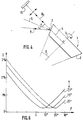
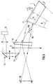
- the scanning device of Figure 4 comprises a regular pyramid trunk 1, here ten flat side faces 2, rotatably mounted around the axis of symmetry 3 of the pyramid trunk.
- the lateral faces, or facets, 2 have, on the axis 3, an inclination ⁇ which varies slightly from one face to the other.
- An incident beam Ri of parallel rays coming from an observed scene, is reflected on one of the faces 2 to form a reflected beam Rd striking a strip of detectors 15.
- the reflected beam Rd is in a plane 4 perpendicular to the axis 3 and forms, with the normal 5 at the surface 2 considered, an angle i.
- the incident beam Ri forms, symmetrically, this same angle i with the normal 5.
- Ten contiguous bands making it possible to reconstruct the overall image are provided at each turn of the trunk of pyramid 1.
- the angle i of deflection of the facets 2 therefore varies slightly, following the variations of the angle ⁇ .
- an average value for each of these angles we consider, in the rest of this presentation, an average value for each of these angles.
- the direction of the beams is an average direction, corresponding to the rays reaching the bar 15 in the middle.
- a parallel beam coming from the observed scene crosses an objective 10 to form the incident beam Ri which crosses an eyepiece 11 then a prism 12, of apex angle here equal to 3 degrees, to reach one of the sides 2 of the pyramid trunk 1.
- the objective 10 and the eyepiece 11 form a magnifying telescope.
- the reflected beam Rd crosses in the opposite direction the prism 12 and the eyepiece 11 to reach a sampling mirror 13 then a deflection optic 14 focusing the beam Rd on the bar 15, which feeds a display or analysis device reconstructing the overall picture.
- the reflected beam Rd is located, with the modulation on the inclination of the faces 2 near, substantially in the plane 4 normal to the axis 3, so that the image of each strip B2 of the scene, represented in FIG. 2 , is free of shear.
- the prism 12 corrects the image of FIG. 2 to give it the rectangular shape presented in FIG. 3, formed by rectangular strips B3. Otherwise the image would be, as shown in Figure 2, fan-shaped, with curved B2 bands and two very straight sides, without shearing, but inclined.
- FIG. 6 illustrates the result of the simulation providing the shear D, plotted on the ordinate, as a function of the angle at the apex ⁇ , plotted on the abscissa, for three values of the angle i.
- This shear D expressed as a percent of the half-length of a scanning strip, has a minimum of about 0.25%.
- the mirror 1 can be replaced by another deflector means, deflecting, by reflection or by transmission, the incident beam Ri. It can in particular be a plurality, ten here, of prisms organized in sectors around the axis 3 and having different apex angles, or of prisms mechanically identical but with different indices.
Landscapes
- Physics & Mathematics (AREA)
- General Physics & Mathematics (AREA)
- Optics & Photonics (AREA)
- Health & Medical Sciences (AREA)
- Electromagnetism (AREA)
- Toxicology (AREA)
- Engineering & Computer Science (AREA)
- Multimedia (AREA)
- Signal Processing (AREA)
- Mechanical Optical Scanning Systems (AREA)
- Facsimile Scanning Arrangements (AREA)
- Transforming Light Signals Into Electric Signals (AREA)
Applications Claiming Priority (2)
| Application Number | Priority Date | Filing Date | Title |
|---|---|---|---|
| FR9409891 | 1994-08-10 | ||
| FR9409891A FR2723674B1 (fr) | 1994-08-10 | 1994-08-10 | Dispositif de balayage en particulier pour systeme d'imagerie. |
Publications (2)
| Publication Number | Publication Date |
|---|---|
| EP0696868A1 true EP0696868A1 (de) | 1996-02-14 |
| EP0696868B1 EP0696868B1 (de) | 2000-03-22 |
Family
ID=9466220
Family Applications (1)
| Application Number | Title | Priority Date | Filing Date |
|---|---|---|---|
| EP19950401734 Expired - Lifetime EP0696868B1 (de) | 1994-08-10 | 1995-07-21 | Abtastgerät, insbesondere für Abbildungssystem |
Country Status (3)
| Country | Link |
|---|---|
| EP (1) | EP0696868B1 (de) |
| DE (1) | DE69515759T2 (de) |
| FR (1) | FR2723674B1 (de) |
Cited By (1)
| Publication number | Priority date | Publication date | Assignee | Title |
|---|---|---|---|---|
| GB2355356A (en) * | 1999-08-19 | 2001-04-18 | Hewlett Packard Co | Four beam electrophotographic printing apparatus |
Families Citing this family (1)
| Publication number | Priority date | Publication date | Assignee | Title |
|---|---|---|---|---|
| USD660737S1 (en) | 2009-10-22 | 2012-05-29 | Qinetiq Limited | Identification panel |
Citations (3)
| Publication number | Priority date | Publication date | Assignee | Title |
|---|---|---|---|---|
| US4117331A (en) * | 1976-05-05 | 1978-09-26 | The Marconi Company Limited | Image translation devices |
| US4419692A (en) * | 1981-12-31 | 1983-12-06 | Texas Medical Instruments, Inc. | High speed infrared imaging system |
| FR2656430A1 (fr) * | 1989-12-26 | 1991-06-28 | Telecommunications Sa | Dispositif de balayage et son application aux dispositifsd'analyse. |
-
1994
- 1994-08-10 FR FR9409891A patent/FR2723674B1/fr not_active Expired - Fee Related
-
1995
- 1995-07-21 EP EP19950401734 patent/EP0696868B1/de not_active Expired - Lifetime
- 1995-07-21 DE DE1995615759 patent/DE69515759T2/de not_active Expired - Fee Related
Patent Citations (3)
| Publication number | Priority date | Publication date | Assignee | Title |
|---|---|---|---|---|
| US4117331A (en) * | 1976-05-05 | 1978-09-26 | The Marconi Company Limited | Image translation devices |
| US4419692A (en) * | 1981-12-31 | 1983-12-06 | Texas Medical Instruments, Inc. | High speed infrared imaging system |
| FR2656430A1 (fr) * | 1989-12-26 | 1991-06-28 | Telecommunications Sa | Dispositif de balayage et son application aux dispositifsd'analyse. |
Cited By (2)
| Publication number | Priority date | Publication date | Assignee | Title |
|---|---|---|---|---|
| GB2355356A (en) * | 1999-08-19 | 2001-04-18 | Hewlett Packard Co | Four beam electrophotographic printing apparatus |
| GB2355356B (en) * | 1999-08-19 | 2003-11-12 | Hewlett Packard Co | Four beam electrophotographic printing apparatus |
Also Published As
| Publication number | Publication date |
|---|---|
| FR2723674B1 (fr) | 1996-09-20 |
| DE69515759D1 (de) | 2000-04-27 |
| DE69515759T2 (de) | 2000-11-02 |
| EP0696868B1 (de) | 2000-03-22 |
| FR2723674A1 (fr) | 1996-02-16 |
Similar Documents
| Publication | Publication Date | Title |
|---|---|---|
| CH643364A5 (fr) | Appareil de localisation de position d'un ou plusieurs objets. | |
| FR2503391A1 (fr) | Systeme de balayage optique | |
| EP0270166B1 (de) | Vorrichtung zur Kompensation einer Verzeichnung | |
| EP0353138B1 (de) | Multispektrales Spiegelgerät | |
| EP0407519B1 (de) | Interferometrische aufstellung für fourier-multiplexierte durchlaufspektralabbildungsvorrichtung und spektralabbildungen mit solcher aufstellung | |
| EP0127914B1 (de) | Bilddrehungsfreies Panoramasichtgerät mit mehreren Gesichtsfeldern | |
| EP0432025B1 (de) | Optisches Nachrichtenübertragungssystem | |
| EP0702246B1 (de) | Tragbares Gerät zum Messen der Rückstreuung von Licht | |
| EP0189217A1 (de) | Optisch-mechanischer Analysator mit einem festen telemetrischen Feld | |
| FR2692368A1 (fr) | Dispositif de veille panoramique infrarouge à grande portée et couverture angulaire élevée, notamment en site. | |
| EP0696868B1 (de) | Abtastgerät, insbesondere für Abbildungssystem | |
| FR2541783A1 (fr) | Systeme d'analyse optique a miroirs situes dans un plan d'un disque rotatif | |
| EP0436429B1 (de) | Abtastvorrichtung und ihre Anwendung in Analysevorrichtungen | |
| EP0645020A1 (de) | Rundumsichtgerät mit optimaler raumabdeckung durch aneinanderfügen von sichtfeldern | |
| FR2677775A1 (fr) | Procede et dispositif de balayage pour un dispositif de prise de vue opto-electronique a grand champ et a haute resolution. | |
| WO1993009463A1 (fr) | Dispositif de microbalayage et camera infrarouge equipee d'un tel dispositif | |
| FR2551890A1 (fr) | Dispositif d'analyse de champ spatial pour la localisation angulaire d'objets rayonnants | |
| FR2481794A1 (fr) | Dispositif optique d'analyse d'un champ spatial et de localisation angulaire d'un objet rayonnant dans ce champ | |
| FR2857746A1 (fr) | Spectrometre optique miniaturise a haute resolution | |
| EP1141668B1 (de) | Vorrichtung zum spektralen abblenden in einem optischen bildsensor | |
| EP0614103B1 (de) | Infrarotfernrohr mit Schwingspiegel | |
| FR2831265A1 (fr) | Procede d'observation d'un objet et satellite le mettant en oeuvre | |
| WO1991009334A1 (fr) | Systeme optique d'observation multidirectionnelle autorisant la selection d'une direction | |
| FR2477349A1 (fr) | Dispositif optomecanique de formation d'images video, notamment pour systeme de detection d'images infrarouge | |
| CA2225583A1 (fr) | Systeme optique d'observation comportant un miroir incline biface de pointage/balayage |
Legal Events
| Date | Code | Title | Description |
|---|---|---|---|
| PUAI | Public reference made under article 153(3) epc to a published international application that has entered the european phase |
Free format text: ORIGINAL CODE: 0009012 |
|
| AK | Designated contracting states |
Kind code of ref document: A1 Designated state(s): DE GB IT NL SE |
|
| 17P | Request for examination filed |
Effective date: 19960612 |
|
| RAP1 | Party data changed (applicant data changed or rights of an application transferred) |
Owner name: SAGEM SA |
|
| 17Q | First examination report despatched |
Effective date: 19980609 |
|
| GRAG | Despatch of communication of intention to grant |
Free format text: ORIGINAL CODE: EPIDOS AGRA |
|
| GRAG | Despatch of communication of intention to grant |
Free format text: ORIGINAL CODE: EPIDOS AGRA |
|
| GRAH | Despatch of communication of intention to grant a patent |
Free format text: ORIGINAL CODE: EPIDOS IGRA |
|
| GRAH | Despatch of communication of intention to grant a patent |
Free format text: ORIGINAL CODE: EPIDOS IGRA |
|
| GRAA | (expected) grant |
Free format text: ORIGINAL CODE: 0009210 |
|
| AK | Designated contracting states |
Kind code of ref document: B1 Designated state(s): DE GB IT NL SE |
|
| REF | Corresponds to: |
Ref document number: 69515759 Country of ref document: DE Date of ref document: 20000427 |
|
| ITF | It: translation for a ep patent filed | ||
| GBT | Gb: translation of ep patent filed (gb section 77(6)(a)/1977) |
Effective date: 20000616 |
|
| PLBE | No opposition filed within time limit |
Free format text: ORIGINAL CODE: 0009261 |
|
| STAA | Information on the status of an ep patent application or granted ep patent |
Free format text: STATUS: NO OPPOSITION FILED WITHIN TIME LIMIT |
|
| 26N | No opposition filed | ||
| PGFP | Annual fee paid to national office [announced via postgrant information from national office to epo] |
Ref country code: NL Payment date: 20010618 Year of fee payment: 7 |
|
| PGFP | Annual fee paid to national office [announced via postgrant information from national office to epo] |
Ref country code: SE Payment date: 20010620 Year of fee payment: 7 |
|
| PGFP | Annual fee paid to national office [announced via postgrant information from national office to epo] |
Ref country code: GB Payment date: 20010713 Year of fee payment: 7 |
|
| PGFP | Annual fee paid to national office [announced via postgrant information from national office to epo] |
Ref country code: DE Payment date: 20010717 Year of fee payment: 7 |
|
| REG | Reference to a national code |
Ref country code: GB Ref legal event code: IF02 |
|
| PG25 | Lapsed in a contracting state [announced via postgrant information from national office to epo] |
Ref country code: GB Free format text: LAPSE BECAUSE OF NON-PAYMENT OF DUE FEES Effective date: 20020721 |
|
| PG25 | Lapsed in a contracting state [announced via postgrant information from national office to epo] |
Ref country code: SE Free format text: LAPSE BECAUSE OF NON-PAYMENT OF DUE FEES Effective date: 20020722 |
|
| PG25 | Lapsed in a contracting state [announced via postgrant information from national office to epo] |
Ref country code: NL Free format text: LAPSE BECAUSE OF NON-PAYMENT OF DUE FEES Effective date: 20030201 Ref country code: DE Free format text: LAPSE BECAUSE OF NON-PAYMENT OF DUE FEES Effective date: 20030201 |
|
| EUG | Se: european patent has lapsed | ||
| GBPC | Gb: european patent ceased through non-payment of renewal fee |
Effective date: 20020721 |
|
| NLV4 | Nl: lapsed or anulled due to non-payment of the annual fee |
Effective date: 20030201 |
|
| PG25 | Lapsed in a contracting state [announced via postgrant information from national office to epo] |
Ref country code: IT Free format text: LAPSE BECAUSE OF NON-PAYMENT OF DUE FEES;WARNING: LAPSES OF ITALIAN PATENTS WITH EFFECTIVE DATE BEFORE 2007 MAY HAVE OCCURRED AT ANY TIME BEFORE 2007. THE CORRECT EFFECTIVE DATE MAY BE DIFFERENT FROM THE ONE RECORDED. Effective date: 20050721 |