EP0189217A1 - Optisch-mechanischer Analysator mit einem festen telemetrischen Feld - Google Patents
Optisch-mechanischer Analysator mit einem festen telemetrischen Feld Download PDFInfo
- Publication number
- EP0189217A1 EP0189217A1 EP86200011A EP86200011A EP0189217A1 EP 0189217 A1 EP0189217 A1 EP 0189217A1 EP 86200011 A EP86200011 A EP 86200011A EP 86200011 A EP86200011 A EP 86200011A EP 0189217 A1 EP0189217 A1 EP 0189217A1
- Authority
- EP
- European Patent Office
- Prior art keywords
- telemetry
- imaging
- transport
- polygon
- mirror
- Prior art date
- Legal status (The legal status is an assumption and is not a legal conclusion. Google has not performed a legal analysis and makes no representation as to the accuracy of the status listed.)
- Granted
Links
- 238000003384 imaging method Methods 0.000 claims abstract description 45
- 230000003287 optical effect Effects 0.000 claims abstract description 18
- 210000001747 pupil Anatomy 0.000 claims description 28
- 230000015572 biosynthetic process Effects 0.000 claims description 4
- 230000001960 triggered effect Effects 0.000 claims description 4
- 238000001514 detection method Methods 0.000 claims description 3
- 238000010304 firing Methods 0.000 claims description 3
- 230000035945 sensitivity Effects 0.000 claims description 2
- 230000003595 spectral effect Effects 0.000 claims description 2
- 230000005540 biological transmission Effects 0.000 claims 1
- 230000004297 night vision Effects 0.000 abstract 1
- 238000010586 diagram Methods 0.000 description 5
- 238000000034 method Methods 0.000 description 3
- 238000001931 thermography Methods 0.000 description 3
- 229910052732 germanium Inorganic materials 0.000 description 2
- GNPVGFCGXDBREM-UHFFFAOYSA-N germanium atom Chemical compound [Ge] GNPVGFCGXDBREM-UHFFFAOYSA-N 0.000 description 2
- 241001080024 Telles Species 0.000 description 1
- 230000002745 absorbent Effects 0.000 description 1
- 239000002250 absorbent Substances 0.000 description 1
- 230000007547 defect Effects 0.000 description 1
- 235000021183 entrée Nutrition 0.000 description 1
- 210000000887 face Anatomy 0.000 description 1
- 238000012986 modification Methods 0.000 description 1
- 230000004048 modification Effects 0.000 description 1
- 230000005855 radiation Effects 0.000 description 1
- 238000001228 spectrum Methods 0.000 description 1
- 230000001360 synchronised effect Effects 0.000 description 1
Images


Classifications
-
- G—PHYSICS
- G01—MEASURING; TESTING
- G01S—RADIO DIRECTION-FINDING; RADIO NAVIGATION; DETERMINING DISTANCE OR VELOCITY BY USE OF RADIO WAVES; LOCATING OR PRESENCE-DETECTING BY USE OF THE REFLECTION OR RERADIATION OF RADIO WAVES; ANALOGOUS ARRANGEMENTS USING OTHER WAVES
- G01S7/00—Details of systems according to groups G01S13/00, G01S15/00, G01S17/00
- G01S7/48—Details of systems according to groups G01S13/00, G01S15/00, G01S17/00 of systems according to group G01S17/00
- G01S7/481—Constructional features, e.g. arrangements of optical elements
- G01S7/4817—Constructional features, e.g. arrangements of optical elements relating to scanning
-
- F—MECHANICAL ENGINEERING; LIGHTING; HEATING; WEAPONS; BLASTING
- F41—WEAPONS
- F41G—WEAPON SIGHTS; AIMING
- F41G3/00—Aiming or laying means
- F41G3/06—Aiming or laying means with rangefinder
- F41G3/065—Structural association of sighting-devices with laser telemeters
-
- G—PHYSICS
- G01—MEASURING; TESTING
- G01S—RADIO DIRECTION-FINDING; RADIO NAVIGATION; DETERMINING DISTANCE OR VELOCITY BY USE OF RADIO WAVES; LOCATING OR PRESENCE-DETECTING BY USE OF THE REFLECTION OR RERADIATION OF RADIO WAVES; ANALOGOUS ARRANGEMENTS USING OTHER WAVES
- G01S17/00—Systems using the reflection or reradiation of electromagnetic waves other than radio waves, e.g. lidar systems
- G01S17/86—Combinations of lidar systems with systems other than lidar, radar or sonar, e.g. with direction finders
-
- G—PHYSICS
- G01—MEASURING; TESTING
- G01S—RADIO DIRECTION-FINDING; RADIO NAVIGATION; DETERMINING DISTANCE OR VELOCITY BY USE OF RADIO WAVES; LOCATING OR PRESENCE-DETECTING BY USE OF THE REFLECTION OR RERADIATION OF RADIO WAVES; ANALOGOUS ARRANGEMENTS USING OTHER WAVES
- G01S17/00—Systems using the reflection or reradiation of electromagnetic waves other than radio waves, e.g. lidar systems
- G01S17/87—Combinations of systems using electromagnetic waves other than radio waves
-
- G—PHYSICS
- G01—MEASURING; TESTING
- G01S—RADIO DIRECTION-FINDING; RADIO NAVIGATION; DETERMINING DISTANCE OR VELOCITY BY USE OF RADIO WAVES; LOCATING OR PRESENCE-DETECTING BY USE OF THE REFLECTION OR RERADIATION OF RADIO WAVES; ANALOGOUS ARRANGEMENTS USING OTHER WAVES
- G01S7/00—Details of systems according to groups G01S13/00, G01S15/00, G01S17/00
- G01S7/48—Details of systems according to groups G01S13/00, G01S15/00, G01S17/00 of systems according to group G01S17/00
- G01S7/481—Constructional features, e.g. arrangements of optical elements
- G01S7/4811—Constructional features, e.g. arrangements of optical elements common to transmitter and receiver
-
- G—PHYSICS
- G02—OPTICS
- G02B—OPTICAL ELEMENTS, SYSTEMS OR APPARATUS
- G02B23/00—Telescopes, e.g. binoculars; Periscopes; Instruments for viewing the inside of hollow bodies; Viewfinders; Optical aiming or sighting devices
- G02B23/12—Telescopes, e.g. binoculars; Periscopes; Instruments for viewing the inside of hollow bodies; Viewfinders; Optical aiming or sighting devices with means for image conversion or intensification
-
- G—PHYSICS
- G02—OPTICS
- G02B—OPTICAL ELEMENTS, SYSTEMS OR APPARATUS
- G02B26/00—Optical devices or arrangements for the control of light using movable or deformable optical elements
- G02B26/08—Optical devices or arrangements for the control of light using movable or deformable optical elements for controlling the direction of light
- G02B26/10—Scanning systems
- G02B26/12—Scanning systems using multifaceted mirrors
- G02B26/129—Systems in which the scanning light beam is repeatedly reflected from the polygonal mirror
Definitions
- the invention relates to an optico-mechanical analyzer having associated imaging and telemetry functions, the imaging field being obtained by line scanning and frame scanning means and the telemetry receiving field being fixed during the time of propagation of a telemetry echo whose emitting source in the imaging spectral sensitivity band is a laser, the beams coming from said fields converging respectively on an imaging detection system and on a telemetry detector placed in the same space cooled.
- Thermal imaging systems are known in which the scene is analyzed point by point by means of an optico-mechanical analyzer. These thermal imaging cameras are generally equipped with large diameter infrared optics.
- the rangefinder's emission and reception optics also have large diameters.
- the laser emission is external to the thermal camera; it uses a separate optic whose axis is parallel to the axis of the laser reception.
- Line scanning can also be bypassed sequentially using switchable optical elements.
- the object of the invention is to overcome these drawbacks by means of another method which defines for the telemetry path a fixed direction of the space independent of the line analysis.
- said imaging and telemetry beams pass through a common input optic and a set of fixed optical elements arranged so as to separate them along two separate optical paths such that the telemetry beam crosses said twice line scanning means, which gives it a fixed direction of space independent of line analysis, said imaging and telemetry functions being simultaneous, not requiring switching of optical elements and firing laser being triggered for a particular position of said line scanning and raster scanning means.
- the embodiment of the optico-mechanical analysis system shown in Figure 1 has an analysis field of ⁇ 30 ° with an entrance pupil having a diameter of 12.5 mm. It can be preceded by an afocal system for the observation of a narrow field. For example with an afocal of magnification 20, the field is 3 ° x 3 ° with an entrance pupil of 250 mm in diameter.
- the virtual image D " 1 of D1 in the reflecting mirror M2 is located on the focal surface of the concentric pupil transport M3 and L 2 with center C.
- the frame mirror M1 rotates around the axis OC 'image of OC in the mirror M2.
- the dioptric transport L1 is composed of two lenses L ' 1 and L " 1.
- the lens L" 1 has its focus in D' 1 . It is centered on the axis D ' 1 C'.
- the lens L'1 is centered on the axis BD1 parallel to D ' 1 C'.
- the plane of the mosaic of detectors D1 is perpendicular to the axis BD1
- the plane of the image D'i is perpendicular to D ' 1 C'
- the plane of the image D " 1 is perpendicular to the axis main CD " 1 .
- the entrance pupil of the analyzer is substantially located on the M4 face of the polygon which rotates around an axis perpendicular to the plane of the figure.
- the pupil transport L 2 + M3 forms the image of this entrance pupil on the weft mirror M1 animated by a sawtooth movement around the axis OC '.
- detector D1 The field of view of detector D1 is fixed.
- the scanning efficiency is approximately 0.8 for the weft movement (this is the ratio of the scanning times to the instants of passage at the maximum amplitude and of rapid return to the zero amplitude for this mode of scanning in teeth saw).
- the scanning efficiency is approximately 0.5 for the line movement. This value is due to the fact that the imaging beam rotates at an angle half that of the radius of the polygon.
- the telemetry beam coming from the detector D2 in the opposite direction of the path of the median incident beam coming from the field of vision converges in D ' 2 real image of D2 formed by the elements M1 and L1.
- D " 2A is the position at the time of the laser shot;
- D" 2B is the position at the time of reception of the laser echo for the maximum range of the laser rangefinder.
- the block diagram of Figure 1 corresponds to this last position.
- the telemetry path is thus different from the imaging path.
- the telemetry function requires no switching of optical elements.
- the telemetry and imaging functions are simultaneous. While the image of the landscape given by the imagery path scans the detectors D1 during the rotation of the polygon, the image of the landscape given by the telemetry path is fixed on the detector D2 when the polygon rotates.
- the fixity of the telemetry field for this exemplary embodiment of the analyzer is approximately achieved if the position of the polygon with respect to CD " 1 is chosen so that HD" 2A is substantially equal to CD " 1 at the time of the firing of telemetry, H being the trace on the polygon of the axis of the beam passing through D " 2 . This field coincides with the analyzer's crosshairs.
- the laser shot synchronized with the scans of the analyzer is triggered when the weft mirror is in the "center of the vertical field” position and when the polygon is in the "center of the field + 8 °" position.
- Telemetry is possible between the positions of the polygon "center of field + 8 °" corresponding to a target at zero distance and "center of field + 12 °" corresponding to a target at 9 km. This limitation is linked to the design of the optical elements of the pupil transport.
- the movement of the raster mirror can be neglected with respect to the extent of the telemetry field.
- the analyzer's reticle is positioned in the center of the laser receiving field.
- the function which determines the formation of this reticle comprises a rectangular source S of 50 ⁇ m x 400 ⁇ m, a reflecting mirror M7 of the beam coming from said source on the face of first reflection M5 of the telemetry beam on the polygon and the other elements telemetry path optics; the elements L 3 , L 4 , M6 of the image transport, the frame mirror M1 and the dioptric transport L1, ensure the formation of a real image of the source S on a detector for triggering the reticle D3 placed in the same vase Dewar as the D1 imaging and D2 telemetry detectors.
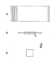
- Figure 2 shows all three detectors located in a common Dewar vessel.
- the D1 imaging detector consists of 31 rectangular elements or SPRITE (trade name) each having the dimensions of 62.5 ⁇ m x 700 ⁇ m.
- the D2 telemetry detector is a square element of 300 ⁇ m x 300 ⁇ m.
- the D3 reticle trigger detector is made up of two rectangular elements of 50 ⁇ m x 500 ⁇ m.
- the image S 'of the source represented in dotted lines scans the detector D3 in the horizontal and vertical directions.
- the scanning in the horizontal direction causes at the instant of the passage of this image over the two elements of the detector D3 the simultaneous emission of two signals whose amplitudes are respectively proportional to the surfaces of the two elements of D3 covered by S 'and the triggering the appearance of the vertical crosshair bar.
- the result of the comparison of the amplitude of these two signals triggers during the equality of the signals the appearance of the horizontal bar of the reticle.
- the frame mirror M1 then occupies the "center of field" position. This device is completed by an analog sensor fixed on the mirror M1 and which controls the amplitude of the sawtooth of the vertical scan.
- the reticle's stability is obtained thanks to the optical path which is very largely common with the telemetry path.
- the harmonization between the telemetry field and the reticle is therefore independent of any drifts of all the optical elements common to the two paths.
- FIG. 3 representing a first variant of the embodiment of the optico-mechanical analyzer according to the invention
- the elements corresponding to those of FIG. 1 are given the same reference signs.
- the image transport of the telemetry path has been modified so that the image D ' 2 of the detector D2 is located at the focus of a lens L 5 so that the telemetry beam first deflected by a plane mirror M7 is then projected in parallel beam on the M5 face of the polygon.
- the beam reflected on this face is taken up by a focusing and deflection system comprising a lens L 6 associated with the plane deflection mirrors M8 and M9 to be focused on the focal surface of the pupil transport from D " 2A to D" 2B following the angular variation of the polygon.
- the telemetry beam is then projected to infinity as indicated above.
- the position of the polygon indicated in dotted lines in FIG. 3 corresponds to laser shooting.
- the maximum range of the rangefinder is reached and the polygon comes to the position indicated in solid lines corresponding to the instant of reception of the laser echo.
- the modification made in this first variant makes it possible to obtain a direction of projection of the telemetry beam strictly independent of the angular position of the polygon. It is necessary and sufficient for this that the focal distance of the lens L 6 is equal to the focal distance of the pupil transport L 2 + M3.
- FIG. 4 represents a second variant of the embodiment of the optico-mechanical analyzer according to the invention and in which the elements corresponding to those of FIGS. 1 and 2 are assigned the same reference signs.
- the telemetry function is taken up from the beam coming from the image D ′ 2 of the detector which is always formed at the focal point of the lens L 5 associated with the reflecting mirror M7.
- the originality of this variant of the analyzer consists in using the pupil transport to constitute said focusing and returning system. After its first reflection on the polygon in parallel beam, the telemetry beam therefore crosses the pupil transport L 2 + M3 and comes to focus in D " 2A ... D" 2B according to the angular variation of the polygon.
- a convex spherical mirror M10 combined with the focal surface of the pupil transport returns the beam on M3 then on the polygon through L 2 .
- the two halves of L 2 + M3 obviously having the same focal distance, the direction of the telemetry beam is independent of the angular position of the polygon.
- the two variants of the analyzer also have a reticle function not shown and such that the beam from a source follows the path of the telemetry beam after reflection on a face of the polygon.
- the addition of the telemetry channel does not modify the performance of the imaging channel.
Landscapes
- Physics & Mathematics (AREA)
- Engineering & Computer Science (AREA)
- General Physics & Mathematics (AREA)
- Radar, Positioning & Navigation (AREA)
- Remote Sensing (AREA)
- Computer Networks & Wireless Communication (AREA)
- Optics & Photonics (AREA)
- Electromagnetism (AREA)
- Astronomy & Astrophysics (AREA)
- General Engineering & Computer Science (AREA)
- Length Measuring Devices By Optical Means (AREA)
- Mechanical Optical Scanning Systems (AREA)
Applications Claiming Priority (2)
| Application Number | Priority Date | Filing Date | Title |
|---|---|---|---|
| FR8500338 | 1985-01-11 | ||
| FR8500338A FR2576114B1 (fr) | 1985-01-11 | 1985-01-11 | Analyseur optico-mecanique ayant un champ de telemetrie fixe |
Publications (2)
| Publication Number | Publication Date |
|---|---|
| EP0189217A1 true EP0189217A1 (de) | 1986-07-30 |
| EP0189217B1 EP0189217B1 (de) | 1989-11-23 |
Family
ID=9315175
Family Applications (1)
| Application Number | Title | Priority Date | Filing Date |
|---|---|---|---|
| EP86200011A Expired EP0189217B1 (de) | 1985-01-11 | 1986-01-08 | Optisch-mechanischer Analysator mit einem festen telemetrischen Feld |
Country Status (4)
| Country | Link |
|---|---|
| US (1) | US4710621A (de) |
| EP (1) | EP0189217B1 (de) |
| DE (1) | DE3667105D1 (de) |
| FR (1) | FR2576114B1 (de) |
Cited By (5)
| Publication number | Priority date | Publication date | Assignee | Title |
|---|---|---|---|---|
| WO1987005766A1 (en) * | 1986-03-21 | 1987-09-24 | Eastman Kodak Company | High resolution optical scanner |
| EP0283222A3 (en) * | 1987-03-20 | 1989-03-15 | Digital Optronics Corporation | 3-dimensional vision system utilizing coherent optical detection |
| EP0473866A3 (en) * | 1990-08-22 | 1993-01-20 | Kollmorgen Corporation | Collision avoidance system |
| EP0580407A1 (de) * | 1992-07-20 | 1994-01-26 | Hughes Aircraft Company | Abtaster für kleine Winkel |
| EP0573697B1 (de) * | 1992-06-12 | 1997-01-22 | Leuze electronic GmbH + Co. | Lichtelektrische Vorrichtung zum Orten von Hindernissen |
Families Citing this family (6)
| Publication number | Priority date | Publication date | Assignee | Title |
|---|---|---|---|---|
| US4902893A (en) * | 1988-04-20 | 1990-02-20 | Burrer Gordon J | Passive infrared radiation scanning system |
| US4978184A (en) * | 1988-10-20 | 1990-12-18 | The Gerber Scientific Instrument Company | Laser raster scanner having passive facet tracking |
| US4993793A (en) * | 1989-05-15 | 1991-02-19 | Fowers Michael B | Machine for splitting and controlling a light beam |
| FR2817339B1 (fr) * | 2000-11-24 | 2004-05-14 | Mensi | Dispositif de relevement tridimensionnel d'une scene a emission laser |
| US10942257B2 (en) * | 2016-12-31 | 2021-03-09 | Innovusion Ireland Limited | 2D scanning high precision LiDAR using combination of rotating concave mirror and beam steering devices |
| US11024669B2 (en) * | 2018-10-24 | 2021-06-01 | Aeva, Inc. | LIDAR system with fiber tip reimaging |
Citations (3)
| Publication number | Priority date | Publication date | Assignee | Title |
|---|---|---|---|---|
| EP0006727A1 (de) * | 1978-06-26 | 1980-01-09 | Flir Systems, Inc. | Optischer Abtaster |
| DE3104318A1 (de) * | 1980-12-23 | 1982-08-26 | Eltro GmbH, Gesellschaft für Strahlungstechnik, 6900 Heidelberg | Zielverfahren und zugehoerige geraeteanordnung |
| FR2522833A1 (fr) * | 1982-03-03 | 1983-09-09 | Pharos Ab | Dispositif de balayage optique |
Family Cites Families (1)
| Publication number | Priority date | Publication date | Assignee | Title |
|---|---|---|---|---|
| US4542986A (en) * | 1983-03-07 | 1985-09-24 | Texas Instruments Incorporated | Scanner position sensor for an integrated laser/FLIR rangefiner |
-
1985
- 1985-01-11 FR FR8500338A patent/FR2576114B1/fr not_active Expired
-
1986
- 1986-01-08 EP EP86200011A patent/EP0189217B1/de not_active Expired
- 1986-01-08 DE DE8686200011T patent/DE3667105D1/de not_active Expired
-
1987
- 1987-03-09 US US07/023,894 patent/US4710621A/en not_active Expired - Fee Related
Patent Citations (3)
| Publication number | Priority date | Publication date | Assignee | Title |
|---|---|---|---|---|
| EP0006727A1 (de) * | 1978-06-26 | 1980-01-09 | Flir Systems, Inc. | Optischer Abtaster |
| DE3104318A1 (de) * | 1980-12-23 | 1982-08-26 | Eltro GmbH, Gesellschaft für Strahlungstechnik, 6900 Heidelberg | Zielverfahren und zugehoerige geraeteanordnung |
| FR2522833A1 (fr) * | 1982-03-03 | 1983-09-09 | Pharos Ab | Dispositif de balayage optique |
Cited By (5)
| Publication number | Priority date | Publication date | Assignee | Title |
|---|---|---|---|---|
| WO1987005766A1 (en) * | 1986-03-21 | 1987-09-24 | Eastman Kodak Company | High resolution optical scanner |
| EP0283222A3 (en) * | 1987-03-20 | 1989-03-15 | Digital Optronics Corporation | 3-dimensional vision system utilizing coherent optical detection |
| EP0473866A3 (en) * | 1990-08-22 | 1993-01-20 | Kollmorgen Corporation | Collision avoidance system |
| EP0573697B1 (de) * | 1992-06-12 | 1997-01-22 | Leuze electronic GmbH + Co. | Lichtelektrische Vorrichtung zum Orten von Hindernissen |
| EP0580407A1 (de) * | 1992-07-20 | 1994-01-26 | Hughes Aircraft Company | Abtaster für kleine Winkel |
Also Published As
| Publication number | Publication date |
|---|---|
| FR2576114B1 (fr) | 1987-02-13 |
| FR2576114A1 (fr) | 1986-07-18 |
| EP0189217B1 (de) | 1989-11-23 |
| US4710621A (en) | 1987-12-01 |
| DE3667105D1 (en) | 1989-12-28 |
Similar Documents
| Publication | Publication Date | Title |
|---|---|---|
| EP0487385B1 (de) | Kollimierte Anzeigvorrichtung mit einem aussen, axialen, sphärischen Spiegel für einen Simulator | |
| EP1449020B1 (de) | Einrichtung zur schnellen sektoriellen oder panoramischen überwachung ohne anscheinende bewegung | |
| EP0189217B1 (de) | Optisch-mechanischer Analysator mit einem festen telemetrischen Feld | |
| EP1052476B1 (de) | Verfahren und Vorrichtung zum Feststellen von Fluchtungsfehlern eines optischen Instruments | |
| EP0645021B1 (de) | Weitwinkliges infrarot-überwachungsgerät mit grosser reichweite | |
| FR2739944A1 (fr) | Systeme optique pour des vues a grand champ | |
| EP0353138B1 (de) | Multispektrales Spiegelgerät | |
| EP0778958A1 (de) | Vorrichtung zum ausrichten eines beobachtungsinstrumentes | |
| EP0702246A1 (de) | Tragbares Gerät zum Messen der Rückstreuung von Licht | |
| EP0187687B1 (de) | Optisch-mechanische Abtasteinheit mit festem Feld zur Entfernungsmessung | |
| FR2692369A1 (fr) | Dispositif de veille omnidirectionnel à couverture optimale de l'espace environnant par jonction de champs. | |
| FR2586520A2 (fr) | Dispositif de balayage optico-mecanique | |
| FR2481794A1 (fr) | Dispositif optique d'analyse d'un champ spatial et de localisation angulaire d'un objet rayonnant dans ce champ | |
| EP0610635B1 (de) | Optische Anordnung zur Kalibrierung einer Wärmebildkamera | |
| EP0696868B1 (de) | Abtastgerät, insbesondere für Abbildungssystem | |
| FR2585204A1 (fr) | Dispositif de balayage optico-mecanique | |
| FR2634903A1 (fr) | Radar a laser infrarouge | |
| FR2709840A1 (fr) | Dispositif optique de type fish-eye pour la détection et la localisation d'une source rayonnante. | |
| EP1141668B1 (de) | Vorrichtung zum spektralen abblenden in einem optischen bildsensor | |
| FR2681749A1 (fr) | Dispositif de balayage opticomecanique bidimensionnel a plusieurs champs d'analyse. | |
| EP0713116A1 (de) | Anamorphotisches System und Wärmebildgerät mit einem derartigen System | |
| FR2477349A1 (fr) | Dispositif optomecanique de formation d'images video, notamment pour systeme de detection d'images infrarouge | |
| WO2007045638A1 (fr) | Dispositif optique multi-parametrable de double-balayage laser | |
| FR2753282A1 (fr) | Systeme optique a rotation d'image et systeme d'observation le comportant | |
| FR2533326A1 (fr) | Dispositif viseur a champ instantane agrandi comportant un miroir et procede de fabrication de ce miroir |
Legal Events
| Date | Code | Title | Description |
|---|---|---|---|
| PUAI | Public reference made under article 153(3) epc to a published international application that has entered the european phase |
Free format text: ORIGINAL CODE: 0009012 |
|
| AK | Designated contracting states |
Kind code of ref document: A1 Designated state(s): BE DE FR GB IT NL |
|
| 17P | Request for examination filed |
Effective date: 19861121 |
|
| 17Q | First examination report despatched |
Effective date: 19880624 |
|
| GRAA | (expected) grant |
Free format text: ORIGINAL CODE: 0009210 |
|
| AK | Designated contracting states |
Kind code of ref document: B1 Designated state(s): BE DE FR GB IT NL |
|
| REF | Corresponds to: |
Ref document number: 3667105 Country of ref document: DE Date of ref document: 19891228 |
|
| ITF | It: translation for a ep patent filed | ||
| GBT | Gb: translation of ep patent filed (gb section 77(6)(a)/1977) | ||
| PLBE | No opposition filed within time limit |
Free format text: ORIGINAL CODE: 0009261 |
|
| STAA | Information on the status of an ep patent application or granted ep patent |
Free format text: STATUS: NO OPPOSITION FILED WITHIN TIME LIMIT |
|
| 26N | No opposition filed | ||
| ITTA | It: last paid annual fee | ||
| REG | Reference to a national code |
Ref country code: GB Ref legal event code: 732E |
|
| NLS | Nl: assignments of ep-patents |
Owner name: THOMSON-TRT DEFENSE TE PARIJS, FRANKRIJK. |
|
| ITPR | It: changes in ownership of a european patent |
Owner name: CESSIONE;THOMSON - TRT DEFENSE |
|
| PGFP | Annual fee paid to national office [announced via postgrant information from national office to epo] |
Ref country code: GB Payment date: 19941219 Year of fee payment: 10 Ref country code: DE Payment date: 19941219 Year of fee payment: 10 |
|
| PGFP | Annual fee paid to national office [announced via postgrant information from national office to epo] |
Ref country code: BE Payment date: 19950104 Year of fee payment: 10 |
|
| PGFP | Annual fee paid to national office [announced via postgrant information from national office to epo] |
Ref country code: FR Payment date: 19950124 Year of fee payment: 10 |
|
| PGFP | Annual fee paid to national office [announced via postgrant information from national office to epo] |
Ref country code: NL Payment date: 19950131 Year of fee payment: 10 |
|
| PG25 | Lapsed in a contracting state [announced via postgrant information from national office to epo] |
Ref country code: GB Effective date: 19960108 |
|
| PG25 | Lapsed in a contracting state [announced via postgrant information from national office to epo] |
Ref country code: BE Effective date: 19960131 |
|
| BERE | Be: lapsed |
Owner name: THOMSON-TRT DEFENSE Effective date: 19960131 |
|
| PG25 | Lapsed in a contracting state [announced via postgrant information from national office to epo] |
Ref country code: NL Effective date: 19960801 |
|
| GBPC | Gb: european patent ceased through non-payment of renewal fee |
Effective date: 19960108 |
|
| PG25 | Lapsed in a contracting state [announced via postgrant information from national office to epo] |
Ref country code: FR Effective date: 19960930 |
|
| NLV4 | Nl: lapsed or anulled due to non-payment of the annual fee |
Effective date: 19960801 |
|
| PG25 | Lapsed in a contracting state [announced via postgrant information from national office to epo] |
Ref country code: DE Effective date: 19961001 |
|
| REG | Reference to a national code |
Ref country code: FR Ref legal event code: ST |
|
| PG25 | Lapsed in a contracting state [announced via postgrant information from national office to epo] |
Ref country code: IT Free format text: LAPSE BECAUSE OF NON-PAYMENT OF DUE FEES;WARNING: LAPSES OF ITALIAN PATENTS WITH EFFECTIVE DATE BEFORE 2007 MAY HAVE OCCURRED AT ANY TIME BEFORE 2007. THE CORRECT EFFECTIVE DATE MAY BE DIFFERENT FROM THE ONE RECORDED. Effective date: 20050108 |