EP0696895B1 - Korb für gargerät - Google Patents
Korb für gargerät Download PDFInfo
- Publication number
- EP0696895B1 EP0696895B1 EP94913457A EP94913457A EP0696895B1 EP 0696895 B1 EP0696895 B1 EP 0696895B1 EP 94913457 A EP94913457 A EP 94913457A EP 94913457 A EP94913457 A EP 94913457A EP 0696895 B1 EP0696895 B1 EP 0696895B1
- Authority
- EP
- European Patent Office
- Prior art keywords
- basket
- linking
- handle
- support
- bar
- Prior art date
- Legal status (The legal status is an assumption and is not a legal conclusion. Google has not performed a legal analysis and makes no representation as to the accuracy of the status listed.)
- Expired - Lifetime
Links
Images


Classifications
-
- A—HUMAN NECESSITIES
- A47—FURNITURE; DOMESTIC ARTICLES OR APPLIANCES; COFFEE MILLS; SPICE MILLS; SUCTION CLEANERS IN GENERAL
- A47J—KITCHEN EQUIPMENT; COFFEE MILLS; SPICE MILLS; APPARATUS FOR MAKING BEVERAGES
- A47J37/00—Baking; Roasting; Grilling; Frying
- A47J37/12—Deep fat fryers, e.g. for frying fish or chips
- A47J37/1219—Deep fat fryers, e.g. for frying fish or chips with means for lowering or raising the frying basket
Definitions
- the present invention relates to a basket for a cooking appliance, in particular a fryer.
- the basket according to the invention is a basket of the type described above.
- the basket according to the invention therefore has all the advantages of the basket following EP-A-0008838.
- the basket according to the invention is provided with a gripping mechanism, which compensates for the horizontal spacing of the basket which is caused by the pivoting of the handle (for example during movement towards the top of basket).
- a gripping mechanism which compensates for the horizontal spacing of the basket which is caused by the pivoting of the handle (for example during movement towards the top of basket).
- the play between the different parts is avoided.
- the basket according to the invention it is possible to keep the basket always in a plane, for example in a horizontal plane, during the pivoting of the handle.
- the basket according to the invention has a first link bar pivotally mounted on the link member, while the second link bar is pivotally mounted on the support, said second link bar being connected to said link member by a means so that the displacement of the connecting member allows the rotation of said second connecting bar.
- the pivot axis of the first bar at least partially follows the movement of the connecting member. This axis is preferably fixed relative to the connecting member.
- the connecting member has a groove or window in which partially extends an element or part of the second connecting bar and in which said element or part slides during the movement of the connecting member.
- the groove or window has an elongated shape and extends in a direction substantially perpendicular to the direction in which the connecting member moves.
- the second connecting bar comprises two parts connected in ink and which extend in different directions, the connecting element or junction of said two parts being the means for allowing the rotation of the second connecting bar during movement of the connecting member.
- the support is provided with an arm on which the basket or part of it acts when the connecting member is in an extreme position of displacement (for example, extreme upper position).
- the invention also relates to a safety or safety device for a handle of a basket of the type described in EP 0008838, this safety serving to maintain the basket in a position relative to the support (for example the extreme upper position or position of the raised basket).
- security includes a leg which is connected to a head; by an effort exerted on the head, said leg being able to be moved in such a way that the leg or part of it is in a position for which after said effort is no longer exerted, the leg or part of it -this touches a support piece of the support so as to maintain the raised position of the basket.
- the connecting member comprises two support plates separated from one another so as to define a passage between them
- the safety comprises a U-shaped member whose legs or wings are each provided with a head or button, part of which extends through an opening in the handle so that the heads or buttons extend partially outside the wall of the handle.
- the member is connected to the handle in such a way that by exerting sufficient pressure on the buttons, the free ends of the legs move towards each other. the other so that said ends can move in said passage when the handle is rotated.
- the subject of the invention is also a system for preventing the handle from being pivotable to lower the basket when the support is not placed or mounted on the cooking appliance and / or if the cover is not closed (position closing the tank).
- This system comprises at least one locking element which is actuated by a member intended to touch a part of the cooking appliance so as to at least partially unlock said locking element.
- the system comprises a locking element which is actuated or controlled by a member intended to touch a part of the cover when the latter is closed, to unlock said locking element.
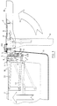
- the basket 1 of the fryer which is represented in FIG. 1 is provided with a handle 2 which can be moved from a substantially vertical position (broken line A) to a substantially horizontal position (B) and vice versa, so as to move up or down the basket 1 in the tank 3.
- the basket 1 is provided with a support 4 which is intended to be placed in an opening of the tank.
- the handle 2 is pivotally connected relative to the support (shaft 120). During the pivoting or rotation of the handle 2, the nose of this handle touches a surface of the support 4, whereby the system 5 for moving the basket 1 in the tank 3 is actuated.
- This system 5 extends through the support 4 between the basket 1 and the handle 2.
- This system comprises a lower link bar 52.
- the upper link bar 51 is pivotally mounted on the support 4 (shaft 510), while that the lower link bar 52 is pivotally mounted on the link or displacement member 6 (shaft 520).
- the free ends of the link bars 51, 52 are pivotally connected to a plate 7 which is fixed to the basket 1.
- the pivot axis 520 of the lower link bar 52 is fixed relative to the link member 6 .
- the upper link bar 51 is connected to the link member 6 by the means 511 so that the displacement of the link member 6 (arrow C) causes the top link bar to pivot (arrow D) 51, while causing a translational movement of the pivot axis 520 of the lower link bar 52.
- a groove 8 (vertical groove) through which partially extends the means or part of bar 511 and in which slides said means (arrow E) during displacement of the connecting member 6.
- the groove 8 is elongated and extends in a direction (E) which is substantially perpendicular to the direction (C) in which the connecting member 6 moves.
- the second link bar or upper link bar 51 comprises two parts 512, 513 which are connected together and which extend in different directions, the connection point or connection element of said two parts being the means for allowing the rotation of the second link bar during movement of the link member.
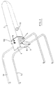
- On the left side as well as on the right side of the basket are connecting bars.
- the upper left link bar is connected to the upper right link bar.
- the support is provided with an arm 9 on which a portion of the upper edge 10 of the basket is pushed when the connecting member 6 is in a position corresponding to the upper extreme position of the basket.
- the handle 2 is provided with safety means 11 for maintaining or guaranteeing a position of the connecting member 6 in which the basket is in its upper position.
- the safety means 11 is a U-shaped member, the legs 110, 111 of which are each provided with a button 112. Each button 112 extends partially out of the casing 12, 13 of the handle 2 and therefore through an opening 14 of a side wall of the two-part envelope.
- the legs 110, 111 are moved towards each other, so that they can be moved between the support plates 16,17. These support plates are carried by the connecting member 6. Then, no more pressure is exerted on the buttons so that after the rotation or pivoting of the handle 2 in position B, the free ends of the legs 110, 111 are supported on the support plates 16, 17.
- the invention also relates to a system for preventing the handle from being pivotable in order to lower the basket when the support is not mounted on the cooking appliance and preferably when the cover is not closed.
- This system 100 consists of a locking means 101 which is actuated or controlled by a member 102 which comes into contact with a part of the cooking appliance when the support is placed or mounted on the cooking appliance, so that the locking element or means is at least partially unlocked.
- the mechanism includes a finger 117 which extends through an opening 140 which is on the upper edge of the support, and on which two plates are fixed.
- One plate 118 is located under the upper edge or face, while the other plate 119 is located above the upper edge.
- a spring 122 extends between the upper edge and the plate 119 so that a force G is exerted on the finger to move this finger outward.
- the plate 118 therefore serves as a means for limiting the inward movement of the finger or rod 117.
- the head 108 is provided with an extension 121 to make a connection between the finger or rod 117 and the head 108.
- This connection is such that when a pressure force is exerted on the finger 117 (against the spring action 122), the head 108 pivots so that the end 109 is no longer in the recess 113, so that the pivoting of the handle to lower the basket 1 is possible.
- This connection can for example be carried out by inserting the extension or extension 121 into a slot or opening 123 of the finger 117.
- the system is in a position for which any pivoting of the handle is prevented and therefore for which the raised position of the basket is maintained. In this position, no pressure is exerted on finger 104 by the device cooking, so that the force F of the spring is sufficient to hold the end 109 of the head 108 in the hollow 113.
- the support is mounted on the cooking appliance, so that a force is exerted on the finger 104 to move the part 103 against the action of the spring 113.
- the cover is closed so that this cover presses on the finger 117 and causes the head 108 to pivot.
- the handle 2 can then, after unlocking the locking means 11, be pivoted to lower the basket into the tank.
Landscapes
- Engineering & Computer Science (AREA)
- Food Science & Technology (AREA)
- Frying-Pans Or Fryers (AREA)
Claims (8)
- Korb (1) für ein Kochgerät mit einem Behälter, wobei der Korb (1) folgendes umfaßt:- einen Träger (4) zur Befestigung an dem Kochgerät;- ein Verbindungsglied (6), das bezüglich des Trägers (4) beweglich ist;- ein Griff (2), der so mit dem beweglichen Verbindungsglied (6) verbunden ist, daß die Drehung des Griffs (2) bezüglich des Trägers (4) ein Verschieben des beweglichen Verbindungsglieds (6) bewirkt, und- zwei Verbindungsstangen, die schwenkbar mit dem Korb verbunden sind, wobei eine erste Verbindungsstange (52), die sich zwischen dem beweglichen Verbindungsglied (6) und dem Korb (1) erstreckt, schwenkbar an dem beweglichen Verbindungsglied (6) angebracht ist,und zwar derart, daß das Verbindungsglied (6) durch die Drehung des Griffs (2) bezüglich des Trägers (4) so verschoben wird, daß es ein Schwenken der Verbindungsstangen und ein Verschieben des Korbs (1) in dem Behälter des Kochgeräts bewirkt,
dadurch gekennzeichnet, daß die zweite Verbindungsstange (51) schwenkbar an dem Träger (4) angebracht und mit dem Verbindungsglied (6) verbunden ist, wobei das Verbindungsglied eine Nut oder einen Ausschnitt (8) aufweist, in die bzw. in den sich ein Teil (511) der zweiten Stange (51) oder ein Element dieser zweiten Stange (51) derart erstreckt, daß das Verschieben des Verbindungsgliedes (6) durch die Drehung des Griffs (2) die Drehung der zweiten Stange (51) bezüglich des Trägers (4) bewirkt. - Korb nach Anspruch 1, dadurch gekennzeichnet, daß der Korb (1) als erste Verbindungsstange (52) eine untere Verbindungsstange, die zum Boden des Korbes (1) hin gerichtet ist, und als zweite Verbindungsstange (51) eine obere Verbindungsstange aufweist.
- Korb nach Anspruch 1 oder 2, dadurch gekennzeichnet, daß die Nut oder der Ausschnitt (8) eine längliche Form aufweist und in einer im wesentlichen senkrecht zu der Richtung, in die das Verbindungsglied (6) verschoben wird, liegenden Richtung verläuft.
- Korb nach einem der Ansprüche 1 bis 3, dadurch gekennzeichnet, daß die zweite Verbindungsstange (51) zwei Teile (512, 513) umfaßt, die miteinander verbunden sind und sich in verschiedene Richtungen erstrecken, wobei sich das Verbindungs- oder Anschlußelement (511) der beiden Teile (512, 513) in die Nut oder den Ausschnitt (8) des Verbindungsglieds (6) erstreckt.
- Korb nach einem der vorhergehenden Ansprüche, dadurch gekennzeichnet, daß der Träger (4) mit einem Arm (9) ausgestattet ist, auf den der Korb (1) oder ein Teil desselben einwirkt, wenn sich das Verbindungsglied (6) in einer äußersten Verschiebungsposition befindet.
- Korb nach einem der vorhergehenden Ansprüche, dadurch gekennzeichnet, daß der Griff (2) mit einer Sicherheitsvorrichtung (11) zum Beibehalten der Position des Verbindungsglieds, in der sich der Korb in seiner bezüglich des Trägers (4) angehobenen Position befindet, ausgestattet ist.
- Korb nach Anspruch 6, dadurch gekennzeichnet, daß die Sicherheitsvorrichtung (11) einen Schenkel (110) umfaßt, der mit einem Kopf (112) verbunden ist; wobei der Schenkel (110) durch eine an den Kopf (112) angelegte Belastung derart verschoben werden kann, daß sich der Schenkel (110) oder ein Teil davon in einer Position befindet, in der, nachdem keine Belastung mehr angelegt ist, der Schenkel (110) oder ein Teil davon ein Stützteil (16) des Glieds (6) so berührt, daß die angehobene Position des Korbs (1) beibehalten wird.
- Korb nach Anspruch 7, dadurch gekennzeichnet, daß das Verbindungsglied (6) zwei Stützplatten (16, 17) umfaßt, die so voneinander getrennt sind, daß sie zwischen sich einen Durchgang definieren, daß die Sicherheitsvorrichtung (11) ein U-förmiges Glied aufweist, dessen Schenkel oder Flügel (110, 111) jeweils mit einem Kopf oder Knopf (112) ausgestattet sind, von dem sich ein Teil derart durch eine Öffnung (14) des Griffs (2) erstreckt, daß sich die Köpfe oder Knöpfe (112) teilweise außerhalb der Wand des Griffs (2) erstrecken, und daß das Glied derart mit dem Griff (2) verbunden ist, daß sich die freien Enden der Schenkel (110, 111) durch Ausübung eines ausreichenden Druckes auf die Knöpfe (112) derart gegeneinander verschieben, daß sich die Enden bei Drehung des Griffs (2) in dem Durchgang verschieben können.
Applications Claiming Priority (2)
| Application Number | Priority Date | Filing Date | Title |
|---|---|---|---|
| BE9300499A BE1007170A5 (nl) | 1993-05-13 | 1993-05-13 | Mand of korf voor kooktoestel. |
| PCT/BE1994/000032 WO1994026157A1 (fr) | 1993-05-13 | 1994-05-11 | Panier pour appareil de cuisson |
Publications (2)
| Publication Number | Publication Date |
|---|---|
| EP0696895A1 EP0696895A1 (de) | 1996-02-21 |
| EP0696895B1 true EP0696895B1 (de) | 1997-04-09 |
Family
ID=3887047
Family Applications (1)
| Application Number | Title | Priority Date | Filing Date |
|---|---|---|---|
| EP94913457A Expired - Lifetime EP0696895B1 (de) | 1993-05-13 | 1994-05-11 | Korb für gargerät |
Country Status (3)
| Country | Link |
|---|---|
| EP (1) | EP0696895B1 (de) |
| BE (1) | BE1007170A5 (de) |
| WO (1) | WO1994026157A1 (de) |
Cited By (1)
| Publication number | Priority date | Publication date | Assignee | Title |
|---|---|---|---|---|
| CN107927024A (zh) * | 2017-12-29 | 2018-04-20 | 浙江帝恒实业有限公司 | 一种自动翻炒的油炸锅 |
Families Citing this family (5)
| Publication number | Priority date | Publication date | Assignee | Title |
|---|---|---|---|---|
| DE19641409A1 (de) * | 1996-10-08 | 1998-04-09 | Bosch Siemens Hausgeraete | Fritiergerät mit drehbarem Handgriff |
| EP0891736A1 (de) * | 1997-07-14 | 1999-01-20 | Yahorng Electronic Co Ltd | Korbhandgriff für Fritiergerät |
| FR2789876B1 (fr) * | 1999-02-19 | 2001-04-06 | Seb Sa | Dispositif de monte et baisse pour panier de cuisson |
| FR2794958B1 (fr) * | 1999-06-18 | 2001-08-31 | Seb Sa | Dispositif de monte et baisse pour panier de cuisson |
| ITUB20155546A1 (it) * | 2015-11-12 | 2017-05-12 | De Longhi Appliances Srl | Apparato di cottura di alimenti e connesso cestello |
Family Cites Families (3)
| Publication number | Priority date | Publication date | Assignee | Title |
|---|---|---|---|---|
| LU64143A1 (de) * | 1971-08-04 | 1972-05-12 | ||
| BE802372A (fr) * | 1973-07-16 | 1974-01-16 | Mat Lmb Sa | Installation pour frire des aliments. |
| DE2967705D1 (de) * | 1978-09-13 | 1992-03-12 | Nova Electro Int | Fritierkorb mit handgriff. |
-
1993
- 1993-05-13 BE BE9300499A patent/BE1007170A5/nl not_active IP Right Cessation
-
1994
- 1994-05-11 EP EP94913457A patent/EP0696895B1/de not_active Expired - Lifetime
- 1994-05-11 WO PCT/BE1994/000032 patent/WO1994026157A1/fr not_active Ceased
Cited By (2)
| Publication number | Priority date | Publication date | Assignee | Title |
|---|---|---|---|---|
| CN107927024A (zh) * | 2017-12-29 | 2018-04-20 | 浙江帝恒实业有限公司 | 一种自动翻炒的油炸锅 |
| CN107927024B (zh) * | 2017-12-29 | 2020-04-24 | 西安智财全技术转移中心有限公司 | 一种自动翻炒的油炸锅 |
Also Published As
| Publication number | Publication date |
|---|---|
| WO1994026157A1 (fr) | 1994-11-24 |
| EP0696895A1 (de) | 1996-02-21 |
| BE1007170A5 (nl) | 1995-04-11 |
Similar Documents
| Publication | Publication Date | Title |
|---|---|---|
| EP0118353B1 (de) | Vorrichtung zur Befestigung eines lösbaren Stiehlgriffs an einem Kochtopf | |
| EP0906742A1 (de) | Abnehmbare vorrichtung zum greifen eines geschirrs | |
| FR2870152A1 (fr) | Couteau pliable multi-usages | |
| FR2997141A3 (fr) | Mousqueton de securite a double blocage | |
| FR2772574A1 (fr) | Dispositif de blocage et de deblocage d'une porte d'un appareil electromenager | |
| EP0341174B1 (de) | Verschluss, insbesondere für Schiebetüren | |
| CA2841680C (fr) | Dispositif de prehension amovible d'un recipient culinaire muni de moyens antiretour de deux bras | |
| EP0270577B1 (de) | Bügelpresse mit integriertem ärmelbrett | |
| EP0696895B1 (de) | Korb für gargerät | |
| EP0620887A1 (de) | Schloss für einen Schrank für elektrische Apparatur. | |
| EP0027746B1 (de) | Vorrichtung zum Verriegeln und Öffnen einer Fahrzeugtür | |
| FR2696779A1 (fr) | Verrou automatique de sécurité pour volets roulants. | |
| EP0721758B1 (de) | Verriegelungs-Entriegelungsvorrichtung für dem Deckel eines Kochgerätes, insbesondere eines Fritiergerätes | |
| FR2639408A1 (fr) | Dispositif de verrouillage automatique pour element articule | |
| FR2588605A1 (fr) | Systeme manoeuvrable d'arret d'un battant de volet et ensemble de crochetage dudit battant. | |
| EP0681799A1 (de) | Blokiervorrichtung für eine Verlängerung Bezüglich eines Möbelstückes, und Möbelstück damit Ausgestattet | |
| FR2683987A1 (fr) | Dispositif de verrouillage-deverrouillage d'un couvercle pour appareil de cuisson. | |
| FR2773449A1 (fr) | Cintre de transport de vetements a bras rabattables | |
| FR2555141A1 (fr) | Couvercle a bec verseur pour la fermeture de pots et autres recipients | |
| FR2915183A1 (fr) | Contenant de type coffre, malle ou cantine a couvercle articule muni d'un dispositif de maintien du couvercle en position ouverte. | |
| EP4514188B1 (de) | Abnehmbarer griff mit einem beweglichen schloss mit einer vorrichtung zur umkehrungsverhinderung | |
| FR2647654A1 (fr) | Dispositif de verrouillage pour une barriere de lit | |
| FR2576629A1 (fr) | Dispositif de renforcement de porte ou similaire. | |
| FR2953705A1 (fr) | Baignoire a porte pour personnes a mobilite reduite | |
| FR2524051A1 (fr) | Verrou a pene coulissant pour ridelles, portes battantes et analogues |
Legal Events
| Date | Code | Title | Description |
|---|---|---|---|
| PUAI | Public reference made under article 153(3) epc to a published international application that has entered the european phase |
Free format text: ORIGINAL CODE: 0009012 |
|
| 17P | Request for examination filed |
Effective date: 19951109 |
|
| AK | Designated contracting states |
Kind code of ref document: A1 Designated state(s): DE FR GB IT |
|
| GRAG | Despatch of communication of intention to grant |
Free format text: ORIGINAL CODE: EPIDOS AGRA |
|
| 17Q | First examination report despatched |
Effective date: 19960415 |
|
| GRAH | Despatch of communication of intention to grant a patent |
Free format text: ORIGINAL CODE: EPIDOS IGRA |
|
| GRAH | Despatch of communication of intention to grant a patent |
Free format text: ORIGINAL CODE: EPIDOS IGRA |
|
| GRAA | (expected) grant |
Free format text: ORIGINAL CODE: 0009210 |
|
| AK | Designated contracting states |
Kind code of ref document: B1 Designated state(s): DE FR GB IT |
|
| PG25 | Lapsed in a contracting state [announced via postgrant information from national office to epo] |
Ref country code: IT Free format text: LAPSE BECAUSE OF FAILURE TO SUBMIT A TRANSLATION OF THE DESCRIPTION OR TO PAY THE FEE WITHIN THE PRE;WARNING: LAPSES OF ITALIAN PATENTS WITH EFFECTIVE DATE BEFORE 2007 MAY HAVE OCCURRED AT ANY TIME BEFORE 2007. THE CORRECT EFFECTIVE DATE MAY BE DIFFERENT FROM THE ONE RECORDED.SCRIBED TIME-LIMIT Effective date: 19970409 Ref country code: GB Effective date: 19970409 |
|
| REF | Corresponds to: |
Ref document number: 69402542 Country of ref document: DE Date of ref document: 19970515 |
|
| PG25 | Lapsed in a contracting state [announced via postgrant information from national office to epo] |
Ref country code: DE Effective date: 19970710 |
|
| GBV | Gb: ep patent (uk) treated as always having been void in accordance with gb section 77(7)/1977 [no translation filed] |
Effective date: 19970409 |
|
| PLBE | No opposition filed within time limit |
Free format text: ORIGINAL CODE: 0009261 |
|
| STAA | Information on the status of an ep patent application or granted ep patent |
Free format text: STATUS: NO OPPOSITION FILED WITHIN TIME LIMIT |
|
| PG25 | Lapsed in a contracting state [announced via postgrant information from national office to epo] |
Ref country code: FR Free format text: LAPSE BECAUSE OF NON-PAYMENT OF DUE FEES Effective date: 19980331 |
|
| 26N | No opposition filed | ||
| REG | Reference to a national code |
Ref country code: FR Ref legal event code: ST |
|
| PG25 | Lapsed in a contracting state [announced via postgrant information from national office to epo] |
Ref country code: FR Free format text: LAPSE BECAUSE OF NON-PAYMENT OF DUE FEES Effective date: 19970531 |