EP0697185A1 - Grill für Restaurants mit modularem Aufbau und der Lastsensibel ist - Google Patents
Grill für Restaurants mit modularem Aufbau und der Lastsensibel ist Download PDFInfo
- Publication number
- EP0697185A1 EP0697185A1 EP95100101A EP95100101A EP0697185A1 EP 0697185 A1 EP0697185 A1 EP 0697185A1 EP 95100101 A EP95100101 A EP 95100101A EP 95100101 A EP95100101 A EP 95100101A EP 0697185 A1 EP0697185 A1 EP 0697185A1
- Authority
- EP
- European Patent Office
- Prior art keywords
- griddle
- plate
- heat
- thermocouple
- steel plate
- Prior art date
- Legal status (The legal status is an assumption and is not a legal conclusion. Google has not performed a legal analysis and makes no representation as to the accuracy of the status listed.)
- Granted
Links
- 238000010276 construction Methods 0.000 title claims abstract description 6
- 238000010438 heat treatment Methods 0.000 claims abstract description 56
- 238000010411 cooking Methods 0.000 claims abstract description 50
- 229910000831 Steel Inorganic materials 0.000 claims abstract description 46
- 239000010959 steel Substances 0.000 claims abstract description 46
- 229910052782 aluminium Inorganic materials 0.000 claims abstract description 17
- XAGFODPZIPBFFR-UHFFFAOYSA-N aluminium Chemical compound [Al] XAGFODPZIPBFFR-UHFFFAOYSA-N 0.000 claims abstract description 17
- YKTSYUJCYHOUJP-UHFFFAOYSA-N [O--].[Al+3].[Al+3].[O-][Si]([O-])([O-])[O-] Chemical compound [O--].[Al+3].[Al+3].[O-][Si]([O-])([O-])[O-] YKTSYUJCYHOUJP-UHFFFAOYSA-N 0.000 claims description 11
- 239000011810 insulating material Substances 0.000 claims description 10
- 239000000463 material Substances 0.000 claims description 7
- 239000007787 solid Substances 0.000 claims description 7
- PXHVJJICTQNCMI-UHFFFAOYSA-N Nickel Chemical compound [Ni] PXHVJJICTQNCMI-UHFFFAOYSA-N 0.000 claims description 6
- 230000007480 spreading Effects 0.000 claims description 4
- VYZAMTAEIAYCRO-UHFFFAOYSA-N Chromium Chemical compound [Cr] VYZAMTAEIAYCRO-UHFFFAOYSA-N 0.000 claims description 3
- 239000004020 conductor Substances 0.000 claims description 3
- 229910052751 metal Inorganic materials 0.000 claims description 3
- 239000002184 metal Substances 0.000 claims description 3
- 229910052759 nickel Inorganic materials 0.000 claims description 3
- 238000009413 insulation Methods 0.000 claims description 2
- 230000001105 regulatory effect Effects 0.000 claims 1
- 230000035945 sensitivity Effects 0.000 claims 1
- 238000009827 uniform distribution Methods 0.000 claims 1
- 238000012423 maintenance Methods 0.000 abstract description 7
- 235000015220 hamburgers Nutrition 0.000 description 5
- 238000001816 cooling Methods 0.000 description 4
- 230000004044 response Effects 0.000 description 4
- 238000004378 air conditioning Methods 0.000 description 3
- 230000008901 benefit Effects 0.000 description 3
- 230000000740 bleeding effect Effects 0.000 description 3
- 239000011152 fibreglass Substances 0.000 description 3
- 235000013305 food Nutrition 0.000 description 3
- 239000004519 grease Substances 0.000 description 3
- 238000009434 installation Methods 0.000 description 3
- 229910001220 stainless steel Inorganic materials 0.000 description 3
- 239000010935 stainless steel Substances 0.000 description 3
- 238000005299 abrasion Methods 0.000 description 2
- 230000008602 contraction Effects 0.000 description 2
- 230000001419 dependent effect Effects 0.000 description 2
- 235000013601 eggs Nutrition 0.000 description 2
- 238000010292 electrical insulation Methods 0.000 description 2
- 239000004744 fabric Substances 0.000 description 2
- 230000005012 migration Effects 0.000 description 2
- 238000013508 migration Methods 0.000 description 2
- 239000002699 waste material Substances 0.000 description 2
- 241000270295 Serpentes Species 0.000 description 1
- 239000012080 ambient air Substances 0.000 description 1
- 230000003466 anti-cipated effect Effects 0.000 description 1
- 238000010420 art technique Methods 0.000 description 1
- 239000006227 byproduct Substances 0.000 description 1
- 230000008859 change Effects 0.000 description 1
- 238000005485 electric heating Methods 0.000 description 1
- 230000005611 electricity Effects 0.000 description 1
- 238000005265 energy consumption Methods 0.000 description 1
- 230000002708 enhancing effect Effects 0.000 description 1
- 239000000835 fiber Substances 0.000 description 1
- 239000011491 glass wool Substances 0.000 description 1
- 230000013011 mating Effects 0.000 description 1
- 239000011159 matrix material Substances 0.000 description 1
- 230000037361 pathway Effects 0.000 description 1
- 239000000047 product Substances 0.000 description 1
- 230000009467 reduction Effects 0.000 description 1
- 238000007790 scraping Methods 0.000 description 1
Images



Classifications
-
- H—ELECTRICITY
- H05—ELECTRIC TECHNIQUES NOT OTHERWISE PROVIDED FOR
- H05B—ELECTRIC HEATING; ELECTRIC LIGHT SOURCES NOT OTHERWISE PROVIDED FOR; CIRCUIT ARRANGEMENTS FOR ELECTRIC LIGHT SOURCES, IN GENERAL
- H05B3/00—Ohmic-resistance heating
- H05B3/68—Heating arrangements specially adapted for cooking plates or analogous hot-plates
- H05B3/72—Plates of sheet metal
-
- A—HUMAN NECESSITIES
- A47—FURNITURE; DOMESTIC ARTICLES OR APPLIANCES; COFFEE MILLS; SPICE MILLS; SUCTION CLEANERS IN GENERAL
- A47J—KITCHEN EQUIPMENT; COFFEE MILLS; SPICE MILLS; APPARATUS FOR MAKING BEVERAGES
- A47J37/00—Baking; Roasting; Grilling; Frying
- A47J37/06—Roasters; Grills; Sandwich grills
- A47J37/067—Horizontally disposed broiling griddles
- A47J37/0676—Horizontally disposed broiling griddles electrically heated
Definitions
- This invention relates to griddles and more particularly to the kind of griddles that are used in restaurants, especially griddles for short order cooking.
- a restaurant type of griddle may have almost any suitable length from two to eight feet, more or less.
- these griddles are arranged to have a plurality of heat zones, each about a foot wide and two feet deep.
- one heat zone might be used for eggs, another for hamburgers, and yet another for pre-heating a food product to a temperature sustainable over a period of time so that the actual cooking time is sharply reduced after receipt of an order.
- other zones may be provided for customized cooking.
- the typical griddle has a massive steel plate in the range of one half to one and a half inches thick.
- the massive nature of the steel plate has been required to reduce the thermal gradients between the heating source pathways and to prevent a griddle warping responsive to thermal expansion and contraction.
- This massive amount of steel provides a high level of thermal inertia and heat uniformity which lends itself to a very long time period for initial heat up or cool down. This slow response time prevents an efficient program for reduction of energy utilization during idle times.
- the massive dimensions of the griddle cause the heat zones to bleed into each other so that the temperature in the hamburger zone, for example, spreads and bleeds over, perhaps a third zone, for example, spreads and bleeds over, perhaps a third of the egg zone with an unpredictable heat gradient in the area of the bleeding temperature.
- the thermostats which control the heating are so far removed from the cooking surface that the thermostat is sensitive to the heating element instead of to the load on the cooking surfaces. If, for example, ten hamburgers (perhaps frozen) are removed from the refrigerator or freezer and immediately placed on the hamburger zone of the hot griddle surface, there is an instant cooling at the cooking surface, which may not be reflected by the thermostat; or, if there is a response, it is only after an extended period of time caused by the thermal inertia of the massive griddle. Thus, the control over the evenness of the cooking temperature is very sluggish, at best. Beyond the obvious draw backs of uneven temperature, the quality of the food served to the customer may suffer.
- a by-product of this sluggish response is that the expense on idle is much higher than it should be. For example, most customers begin arriving at a restaurant for lunch at, say, 11:30 am and stop arriving about 1:30 pm so that the heat supplied to the griddle should be reduced. Before and after these times, there may be only a very few people who expect to eat; however, the griddle can not cool appreciably because those people who do show up still expect to be fed fairly quickly. Therefore, there is a big waste of energy during idle conditions.
- radiated heat is both wasted heat and wasted energy required to produce the heat.
- the heat is very uncomfortable to the cook and to the other people who work in area.
- the radiated heat imposes a higher burden upon air conditioning equipment for the restaurant.
- the wiring, fusing, etc. must be greater, thus creating higher installation costs.
- the rates for the consumed energy may be increased because the electric power company must install enough power generating equipment to adequately supply a surge in demand even if the surge never comes.
- the BTU cost of gas is much less than the corresponding cost of electricity.
- the griddle plate automatically becomes thicker, and therefore, heavier than it would be for electric heat.
- the thicker plate exaggerates the above described problems, such as heat bleeding between zones and the like. For these and other reasons, many if not most, griddles are gas heated, while most cooks prefer the convenience of an electrically heated griddle.
- an object of the invention is to provide a new and improved griddle which over comes the above described problems found in prior griddles.
- an object is to provide a quick response griddle which maintains even heat on the cooking surface.
- an object is to place the thermal couple as close to the cooking surface as possible in order to make the griddle load responsive instead of heating element responsive.
- an object is to provide a plurality of well defined cooking zones with a minimum amount of heat bleeding across zone boundaries.
- a further object is to initially provide a uniform heat source area so that a thick griddle plate is not required to achieve thermal uniformity.
- Another object is to provide an efficient electrically heated griddle, with all of the advantages of electrical heat, but at or near a cost of gas heat.
- an object is to enable a use of solid state, electronic controls which are able to maintain a high accuracy of heat control which can be preprogrammed, as for example, to automatically reduce energy consumption during idle conditions.
- Yet another object of the invention is to provide an easily installed and maintained griddle which is completely serviceable from the front and which is completely modular so that parts may be replaced as a unit with a minimum amount of time and money. Accordingly, an object is to reduce down time to a minimum.
- Still another object of the invention is to provide a better environment for short order cooking. This means a cooler and more comfortable kitchen, a reduced need for wiring and fusing, a reduced demand upon air conditioning, and a conservation of energy usage.
- a griddle having a relatively thin steel plate with a heat spreader for maintaining the uniformity of the heat distribution over each heat zone.
- the heat spreader replaceable modular heating element with an aluminum sheet in intimate contact with the bottom of the steel plate.
- the application of energy to the heating element is under control of a thermocouple located in a hole drilled into the steel plate to a depth which is so near the cooking surface that the control is load sensitive. The only constraint upon the closeness of the holes to the cooking surface is to prevent surface damage responsive to the habit of cooks to scrape the surface many times each day.
- the inventive griddle 20 shown in Fig. 1, which will be sold under the trademark "ACCU-MISER", is a product of the Middleby Corporation.
- the trademark emphasizes the extreme accuracy of the heat control and the low cost of the energy demand.
- the major parts of the inventive griddle are a housing 22, controls mounted on or in connection with a door 26 which may open or swing down for service and maintenance, and a steel plate 28 having a cooking surface on top of the housing.
- the door 26 sets at an angle 29 which makes it easier to see and set the controls. All normal service and maintenance that may reasonably be anticipated may be performed through the housing opening which is exposed when the door 26 is open.
- the cooking surface of steel plate 28 terminates on the front edge in a grease trough 30 having a grease chute or slot 32 therein.
- a removable drawer 34 catches the grease scraped off the cooking surface of plate 28 and through trough and chute.
- the griddle shown in Fig. 1 may be made in any suitable length and with any suitable number of heating zones. As here shown, there are four heating zones, each having its own controls 36, 38.
- the first or left hand heating zone has an on/off switch 36a, temperature selector switch 38a, and pilot lights 40a, 42a. Pilot light 40a indicates whether the zone heating unit is switched on or off. Pilot light 42a lights when the cooking surface temperature has reached the temperature selected by control knob of selector 38.
- the steel griddle plate 28 is surrounded on three sides by a splash guard 44.
- the inventive griddle plate has only to be thick enough so as not to warp responsive to repeated heating and cooling and to stand up to the relative rough usage experienced by almost all griddles.
- the construction of the griddle plate 28 is shown in Fig.1 by broken sections.
- steel griddle plate 28 On the top, there is a steel griddle plate 28 which is preferably three-eighth inch thick with upper and lower surfaces that are ground flat.
- a heat spreader in the form of an aluminum plate 48, which is one-eighth inch thick, for example.
- Aluminum is selected because it has one of the best heat conducting and spreading characteristics. Also, aluminum is soft relative to the hardness of steel and is given to cold flow, so that soon after it is installed, the upper aluminum surface soon adopts the shape of the bottom of steel griddle plate 28, filling in surface valleys and giving way to surface hills.
- Beneath the aluminum plate 48 is a block 50 of aluminum silicate fiber 50 which is a material having a relatively poor heat transmitting characteristic and which is an electrical insulation.
- the top surface of block 50 is covered with a wear resistant surface 118 (see Fig. 9).
- Buried in a serpentine pattern within the block 50 of aluminum silicate is an energy efficient wire 52 which gives off heat when energized. Any suitable resistance wire may be used to heat the griddle.
- the wire is made of nickel-chrome and is located in a plane within the aluminum silicate matrix at a level which is as close to the food as possible (considering a potential electrical hazard) in order to better direct heat in that direction.
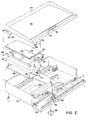
- the griddle assembly is best shown in the exploded view of Fig. 2.
- the steel griddle plate 28 is a separate unit which is attached to the housing 22.
- Dependent from the bottom, near the rear edge, and at opposite sides of the first heat zone of plate 28 are two lugs, one of which is seen at 54. Similar lugs are associated with each heat zone.
- An insulating blanket frame 56 is hinged to and between these two lugs by two screws (one of which is seen at 58) secured in place by a nut 60 and washer 62. Thus, the blanket frame 56 may swing up to an operating position or swing down to a service position.
- the length of lug 54 is such that a heating module 64 fits snugly and exactly between blanket frame 56 and bottom of griddle plate 28 when the blanket frame swings up and is secured to the bottom of plate 28 by any suitable devices, such as bolts, represented at 66, 68.
- the heating module 64 is enclosed within a sheet metal housing 70 which has the heat spreading aluminum plate 48 as the top surface. Enclosed within the housing are the aluminum silicate block 50, and heating wires 52. The electrical connections are made via wires 72 and a terminal block 74. Therefore, to install, replace, or change heat modules one only has to disconnect wires 72, remove bolts 66,68 or another suitable fastener, swing down the blanket frame 56, lift out the old heating module 64, insert a new heating module 64, swing frame 56 up to the capture position, reinstall bolts 66,68, and reconnect wire 72 from the new module to terminal block 74.
- the aluminum plate 48 When the blanket frame 56 is bolted into the capture position the aluminum plate 48 is in an intimate contact with the underside of steel griddle plate 28.
- the aluminum plate 48 includes a slot 76 for receiving a tube (Fig. 4) on the underside of the steel plate through which a thermocouple 78 is inserted.
- the blanket frame 56 and an underlying plate 80 capture between them a blanket 82 of glass wool or another suitable heat insulating material which tends to prevent a loss of heat to the environment.
- a bar or strip of similar insulating material 83 completes the heat insulation. This construction directs heat toward the cooking surface of plate 28, keeps the work area cooler, reduces the need for restaurant air conditioning, and contributes to worker comfort, especially the cook's comfort.
- the blanket frame 56 has cross bars 84, 86 which mate with members 120 (see Fig. 9) on the bottom of heating module 64.
- the mating of these module members 120 and frame cross bars 84, 86 insures that the heating member 64 is correctly positioned.
- thermocouple The installation and mounting of the thermocouple is shown in Figs. 3-6.
- the steel plate 28 has a number of holes 88 drilled there in at an angle A, which may preferably be in the order of about 15°.
- a second hole 90 of a smaller diameter is drilled co-axially into the center of the first hole 88.
- the second hole is drilled to a depth which leaves a minimum unbroken thickness B of steel between the distal end of hole 90 and the top or cooking surface C of the steel griddle plate 28. It has been found that the distance B is best when it is equal to about 0.100 inches.
- the hole 90 should be drilled as far as possible in order to put the thermocouple as near as possible to the cooking surface C.
- the hole must not be drilled so far that the cooking surface C is damaged by the onslaught of cooks who almost constantly scrape the cooking surface C in order to remove any debris that remains clinging to the surface.
- the scraping is with a strong spatula so that the cook may exert a relatively heavy force upon surface C.
- a thin stainless steel tube 92 (Fig. 4) is inserted into the coaxial hole 88 with the largest diameter, bent over and welded to the bottom of the steel griddle plate 28.
- the tube 92 extends to the front edge 94 (Fig. 2) of the griddle plate 28. Therefore, when the door 26 is open, a maintenance man has easy access to the tube 92 at the front of the griddle for replacing the thermocouple.
- thermocouple is shown in Fig. 5 as including a stainless steel tube 78 (about one-sixteenth inch in diameter) which is so very thin that it is very flexible.
- Connector 96 on the proximal end of the thermocouple tube 78 connects a wire 98 to a thermocouple inside the distal tip end of tube 78.
- the opposite end of wire 98 is connected to a solid state controller 100 (Fig. 2) which includes a potentiometer that is adjusted responsive to the sensed temperature.
- thermocouple is inserted through tube 92 until its distal tip end in intimate contact with steel griddle plate 28 (distance B, .100-inches from the cooking surface C).
- thermocouples may be provided at any desired locations on the steel griddle plate 28.
- thermocouple 78 This close and intimate contact between the cooking surface C and thermocouple 78 (Fig. 6) may be compared with the inefficient prior art technique (Fig. 7) where the steel griddle plate 102 is in the range of one half to one and a quarter inches thick.
- the prior art heating elements 104 are suspended below the griddle plate 102. Usually, they are a "Cal-Rod” burner positioned some distance away from the plate.
- the thermocouple 106 is generally in among these "Cal Rod” units on so that it tended to pick up the temperature of the burner and not the temperature on the cooking surface C of the griddle plate 102.
- thermocouple intimate contact with the cooking surface C (Fig. 6).
- the preferred wiring pattern for the resistance heating (nickel-chrome) wire 52 in the inventive heating element is best seen in Fig. 8.
- most heating elements tended to extend along the length of the heating module 64 (front to back in Fig. 2).
- the thermally caused expansion and contraction of the heating rods or wires would destroy block 50 and the resultant anchorage of the heating wire.
- the invention solves this problem by running the wires in a serpentine pattern from side to side (across the narrow direction) of heating module 64.
- Another reason for extending the wire 52 from side by side relates to the problems of heating the edges of the griddle.
- the front edge 94 (Fig.
- the plate is exposed to a natural cooling by ambient air which cooling would not be experienced in the middle of the griddle, for example.
- the plate is exposed to the heat of a different griddle heat zone.
- the left edge of a middle heat zone on the griddle might be heated above the desired temperature by a migration of heat energy from the heat zone of the adjacent heating module.
- the right edge of the same middle heat zone might surrender heat by a migration of heat energy to the heat zone on the right.
- the resistance wire 52 follows a serpentine path wherein the wires which snake back and forth are spaced closer to each other in the two end zones 108, 110 of the heater than in the middle zone 112 of the heater. Accordingly, the wires 52 give off less heat energy in the middle zone which is surrounded by uniformly heated portions of the steel griddle plate 28. The wires 52 give off a more concentrated heat energy in the front and rear zones 108, 110. By carefully spacing the heating wires 52, the heat zone may be given a much more uniform heat than was available heretofore. Since it is an excellent conductor of heat, the aluminum plate 48 further helps to spread the heat evenly and thereby to provide the cooking surface with a greater uniformity of heat.
- the wires 72 are connected from terminal block 74 (Fig. 2) to supply electrical energy to the nickel-chrome heating wires 52.
- the patches 114, 116 are preferably fiber glass fabric cemented to the top of the aluminum silicate block 50 in order to provide a mechanical resistance to abrasion from wires 72.
- thermocouple 78 is buried very near cooking surface C within a coaxial pair of holes in the steel plate 28. Therefore, the monitored temperature is the temperature at the cooking surface C and not the temperature of some point below the bottom of plate 28.
- the aluminum plate 48 is in intimate contact with the entire undersurface of steel griddle plate 28 (except for the location of the thermocouple). This intimate contact spreads the heat more uniformly before it reaches the steel griddle plate.
- an aluminum silicate block 50 having nickel chrome or other resistance heating wires 52 embedded therein. These resistance wires are placed as near as possible to the aluminum heat spreading plate, considering the need for an adequate amount of electrical insulation that is required to avoid an electrical hazard.
- the upper surface of the block is covered by a fiber glass fabric 118. There is no need to so protect the bottom surface of the aluminum silicate block 50 because it is encased in a metal housing 70.
- a thick fiber glass wool blanket 82 provides thermal installation against the heat of the griddle.
- Blanket 82 is enclosed between a blanket frame 56 and a bottom plate 80.
- a cross member 84 is part of frame 56.
- the dependent tab 120 is attached to the bottom plate 70 of the housing encasing the heating If it is properly caught, the heating module is in perfect position.
Landscapes
- Engineering & Computer Science (AREA)
- Food Science & Technology (AREA)
- Baking, Grill, Roasting (AREA)
- Measurement Of Force In General (AREA)
- Slide Fasteners, Snap Fasteners, And Hook Fasteners (AREA)
- Measuring Temperature Or Quantity Of Heat (AREA)
- Artificial Fish Reefs (AREA)
- Electric Stoves And Ranges (AREA)
Applications Claiming Priority (2)
| Application Number | Priority Date | Filing Date | Title |
|---|---|---|---|
| US292738 | 1994-08-18 | ||
| US08/292,738 US5413032A (en) | 1994-08-18 | 1994-08-18 | Restaurant type griddle with modular construction and which is load sensitive |
Publications (2)
| Publication Number | Publication Date |
|---|---|
| EP0697185A1 true EP0697185A1 (de) | 1996-02-21 |
| EP0697185B1 EP0697185B1 (de) | 1998-10-14 |
Family
ID=23125986
Family Applications (1)
| Application Number | Title | Priority Date | Filing Date |
|---|---|---|---|
| EP95100101A Expired - Lifetime EP0697185B1 (de) | 1994-08-18 | 1995-01-05 | Grill für Restaurants mit modularem Aufbau und der Lastsensibel ist |
Country Status (9)
| Country | Link |
|---|---|
| US (1) | US5413032A (de) |
| EP (1) | EP0697185B1 (de) |
| JP (1) | JPH0866318A (de) |
| AT (1) | ATE172088T1 (de) |
| AU (1) | AU673475B2 (de) |
| CA (1) | CA2138109A1 (de) |
| DE (1) | DE69505321T2 (de) |
| DK (1) | DK0697185T3 (de) |
| ES (1) | ES2124435T3 (de) |
Cited By (2)
| Publication number | Priority date | Publication date | Assignee | Title |
|---|---|---|---|---|
| US8074563B2 (en) | 2009-01-29 | 2011-12-13 | General Electric Company | Griddle with a heat spreader |
| EP3598848B1 (de) | 2018-07-19 | 2021-03-31 | E.G.O. Elektro-Gerätebau GmbH | Heizeinrichtung für ein kochfeld und kochfeld |
Families Citing this family (56)
| Publication number | Priority date | Publication date | Assignee | Title |
|---|---|---|---|---|
| JPH0795926A (ja) * | 1993-09-29 | 1995-04-11 | Matsushita Electric Ind Co Ltd | ホットプレート |
| US5676043A (en) * | 1995-10-03 | 1997-10-14 | Best; Willie H. | Griddle assembly having discrete cooking zones |
| US5619910A (en) * | 1996-01-04 | 1997-04-15 | Keating Of Chicago, Inc. | Laminated griddle top |
| US5961866A (en) * | 1996-03-27 | 1999-10-05 | Alto-Shaam, Inc. | Food heating unit |
| US6073542A (en) * | 1998-01-20 | 2000-06-13 | Perez; Primitivo | Portable gas and electric griddle for outdoor-indoor applications |
| US5964145A (en) * | 1998-02-04 | 1999-10-12 | Legion Industries, Inc. | Griddle |
| US6138554A (en) * | 1999-03-12 | 2000-10-31 | Gas Research Institute | Multi-layer griddle |
| USD451334S1 (en) | 2001-02-12 | 2001-12-04 | Vernon R. Dillenbeck | Grill |
| US6389960B1 (en) | 2001-07-12 | 2002-05-21 | Middleby-Marshall, Inc. | Gas-fired cooking device with griddle surface heated by heat bank |
| US6758207B1 (en) | 2003-04-04 | 2004-07-06 | Middleby-Marshall, Inc. | Gas-fired cooking device with braising cavity having surface heated by heat bank |
| ES2313074T3 (es) * | 2003-06-30 | 2009-03-01 | Conair Corporation | Aparato para cocinas reversible. |
| US6837152B1 (en) * | 2003-12-12 | 2005-01-04 | Fancy Food Service Equipment Co., Ltd. | Water-cooled muffler device for a grill apparatus |
| US6914221B1 (en) * | 2004-01-23 | 2005-07-05 | Hatco Corporation | System and method for warming food |
| SG163536A1 (en) * | 2005-06-29 | 2010-08-30 | Watlow Electric Mfg | Smart layered heater surfaces |
| US7647866B2 (en) * | 2005-10-06 | 2010-01-19 | John Edwin Button | Griddle for cooking and preparing foods |
| US20070210064A1 (en) * | 2006-03-06 | 2007-09-13 | Hatco Corporation | System for warming food |
| KR100771628B1 (ko) * | 2006-05-11 | 2007-10-31 | 엘지전자 주식회사 | 전기레인지 |
| WO2009007781A2 (en) * | 2007-07-10 | 2009-01-15 | Premark Feg L.L.C. | Multi-zone composite cooking griddle with unitary thermally conductive plate |
| DE102008008143B4 (de) * | 2008-02-08 | 2010-08-05 | Eisfink Max Maier Gmbh & Co. Kg | Grillvorrichtung |
| US7638738B1 (en) * | 2008-07-03 | 2009-12-29 | Babington Enterprises | Griddle cooking system |
| USD613117S1 (en) * | 2009-10-21 | 2010-04-06 | Henry Alan Richburg | Removable stove top griddle |
| USD614915S1 (en) * | 2009-12-18 | 2010-05-04 | Paul Schnitman | Multipurpose cooking griddle |
| US20120006809A1 (en) * | 2010-06-23 | 2012-01-12 | Colorado State University Research Foundation | Sublimation crucible with embedded heater element |
| USD632925S1 (en) * | 2010-09-24 | 2011-02-22 | Magellan Group Ltd. | Griddle |
| USD676721S1 (en) | 2010-11-22 | 2013-02-26 | John Edwin Button | Grill top griddle |
| DE102010062503A1 (de) | 2010-12-07 | 2012-06-14 | BSH Bosch und Siemens Hausgeräte GmbH | Gargutträger |
| EP2647321B1 (de) * | 2012-04-04 | 2014-12-31 | Eksen Makine Sanayi ve Ticaret A.S. | Toaster mit fixen und verstellbaren mechanischen Thermostaten |
| EP2671482B1 (de) * | 2012-06-05 | 2015-05-06 | Koninklijke Philips N.V. | Grill |
| US9782039B2 (en) | 2014-05-23 | 2017-10-10 | Viking Range, Llc | Griddle |
| US9357879B2 (en) | 2014-05-23 | 2016-06-07 | Viking Range, Llc | Griddle |
| MA41646A (fr) * | 2015-03-05 | 2018-01-09 | Spectrum Brands Inc | Gril de cuisson électrique à usages multiples |
| US10327588B2 (en) | 2016-05-04 | 2019-06-25 | North Atlantic Imports, Llc | Griddle device, system, and method |
| US10327589B1 (en) | 2016-05-04 | 2019-06-25 | North Atlantic Imports, Llc | Outdoor cooking station with griddle, system and method thereof |
| US10524312B2 (en) | 2016-07-01 | 2019-12-31 | Weber-Stephen Products Llc | Electric grill with current protection circuitry |
| US11454677B2 (en) | 2016-07-01 | 2022-09-27 | Weber-Stephen Products Llc | Wireless control and status monitoring for electric grill with current protection circuitry |
| US10537199B2 (en) | 2016-07-01 | 2020-01-21 | Weber-Stephen Products Llc | Digital power supply |
| US10551893B2 (en) | 2016-07-01 | 2020-02-04 | Weber-Stephen Products Llc | Digital power supply with wireless monitoring and control |
| IT201700036911A1 (it) * | 2017-04-04 | 2018-10-04 | Manfred Andergassen | Un'apparecchiatura di barbecue perfezionata |
| IT201700074735A1 (it) * | 2017-07-04 | 2019-01-04 | Airone S R L | Apparecchiatura perfezionata per la cottura di alimenti |
| USD833207S1 (en) * | 2017-07-27 | 2018-11-13 | Mr. Bar-B-Q Products Llc | Griddle with removable tray |
| US10555377B2 (en) * | 2017-11-29 | 2020-02-04 | Shenzhen Chenbei Technology Co., Ltd. | Warmer with integrated heating module |
| FR3088413B1 (fr) * | 2018-11-09 | 2020-12-18 | Rosinox | Systeme de chauffe et appareil de cuisson le comportant |
| USD976643S1 (en) * | 2019-10-29 | 2023-01-31 | Justin Olson | Heater-mountable cooktop |
| US11365888B2 (en) * | 2019-12-05 | 2022-06-21 | Haier Us Appliance Solutions, Inc. | Cooktop appliance with modular griddle system |
| US11877693B2 (en) | 2020-02-11 | 2024-01-23 | North Atlantic Imports, Llc | Griddle cooking station and method thereof |
| USD940496S1 (en) * | 2020-04-22 | 2022-01-11 | Guangzhou Hengfu Hardware Technology Co., Ltd | Teppanyaki grill |
| US11980322B2 (en) * | 2020-07-21 | 2024-05-14 | Nexgrill Industries, Inc. | Outdoor griddle station with grease management system |
| US12359820B2 (en) | 2022-11-18 | 2025-07-15 | Haier Us Appliance Solutions, Inc. | Cooktop including a single input control of multiple heating elements |
| US12352450B2 (en) | 2022-11-23 | 2025-07-08 | Haier Us Appliance Solutions, Inc. | Gas cooktop with griddle assembly including removable temperature probe |
| US12460824B2 (en) | 2022-11-23 | 2025-11-04 | Haier Us Appliance Solutions, Inc. | Gas cooktop with griddle assembly including temperature probe for monitoring failure modes |
| US12270552B2 (en) | 2022-11-23 | 2025-04-08 | Haier Us Appliance Solutions, Inc. | Gas cooktop with griddle assembly including removable temperature probe |
| USD1081245S1 (en) * | 2022-11-29 | 2025-07-01 | Enhong Dai | Griddle |
| KR102544526B1 (ko) * | 2023-02-23 | 2023-06-16 | 주식회사 신성하인스 | 유지 보수가 용이하고 성능이 향상된 인덕션 부침기 |
| USD1007236S1 (en) * | 2023-06-13 | 2023-12-12 | Yinbing Chen | Griddle |
| USD1081244S1 (en) * | 2023-08-02 | 2025-07-01 | Laxminarasimhan Vasan | Griddle |
| USD1059115S1 (en) * | 2023-10-08 | 2025-01-28 | Xiaomei Chen | Teppanyaki grill |
Citations (8)
| Publication number | Priority date | Publication date | Assignee | Title |
|---|---|---|---|---|
| US3317709A (en) * | 1964-05-11 | 1967-05-02 | Mc Graw Edison Co | Electric griddle |
| DE2747553A1 (de) * | 1977-10-22 | 1979-04-26 | Eugen Dr Ing Harsanyi | Tragbares tischgrillgeraet mit waermespeicherelement |
| US4164175A (en) * | 1977-12-01 | 1979-08-14 | Ultra-Heat Corporation | Broilers and electric heaters therefor |
| EP0105175A1 (de) * | 1982-09-07 | 1984-04-11 | Kanthal GmbH | Vakuumgeformte elektrische Heizvorrichtung und Verfahren zu deren Herstellung |
| DE3407965A1 (de) * | 1984-03-03 | 1985-09-05 | E.G.O. Elektro-Geräte Blanc u. Fischer, 7519 Oberderdingen | Grillplatte |
| EP0197905A1 (de) * | 1985-03-22 | 1986-10-15 | Novlab Storkök AB | Kochfläche |
| EP0248699A1 (de) * | 1986-05-30 | 1987-12-09 | Perrichon | Elektrischer Kocher mit hohem Wirkungsgrad, insbesondere für Gast- und Kantinenwirte |
| DE3830327A1 (de) * | 1988-09-07 | 1990-03-15 | Dieter Schanuel | Elektrisch beheizbarer behaelter, wie friteuse, und verfahren zu seiner herstellung |
Family Cites Families (28)
| Publication number | Priority date | Publication date | Assignee | Title |
|---|---|---|---|---|
| US1831889A (en) * | 1931-11-17 | Electrically heated cooking | ||
| US993314A (en) * | 1911-01-03 | 1911-05-23 | Herman Mieth | Electrically-heated vessel. |
| US1112582A (en) * | 1913-10-07 | 1914-10-06 | Frank R Whittlesey | Electric heater. |
| US1465995A (en) * | 1922-03-16 | 1923-08-28 | Robert E Pearson | Electric cooking and heating apparatus |
| US2035147A (en) * | 1934-03-05 | 1936-03-24 | Oliver C Dennis | Electric frying pan |
| US2070482A (en) * | 1935-08-15 | 1937-02-09 | Hawkins Luty | Electrical heating device |
| US2119421A (en) * | 1937-01-22 | 1938-05-31 | James R Cross | Electric cooking utensil |
| US2430715A (en) * | 1942-06-08 | 1947-11-11 | Lowell And Grayson Mfg Company | Electric heater for cooking utensils |
| CH228606A (de) * | 1942-10-05 | 1943-09-15 | Delz & Co W | Elektrische Wärmevorrichtung. |
| US3010006A (en) * | 1953-10-02 | 1961-11-21 | Webcor Inc | Cooking utensil |
| US3047702A (en) * | 1958-10-03 | 1962-07-31 | Fredrick L Lefebvre | Plate heater |
| US3043943A (en) * | 1959-12-24 | 1962-07-10 | Cornwall Corp | Food warmer |
| US3231718A (en) * | 1962-02-05 | 1966-01-25 | Akay Corp | Automatic electric food warmer tray |
| US3245462A (en) * | 1963-08-01 | 1966-04-12 | Speedster Inc | Heavy duty griddle top |
| US3479490A (en) * | 1969-02-06 | 1969-11-18 | Norman H Stark | High temperature infrared radiant heating device |
| US3636299A (en) * | 1970-11-12 | 1972-01-18 | Luther H Stewart Jr | Lazy susan hotplate |
| US3674983A (en) * | 1971-04-08 | 1972-07-04 | Gen Electric | Smooth surface electric cooktop |
| US3715975A (en) * | 1971-05-11 | 1973-02-13 | Speedline Partnership | Food heating device |
| US3739148A (en) * | 1972-01-28 | 1973-06-12 | Gen Electric | Food warming dish |
| US3809859A (en) * | 1973-01-08 | 1974-05-07 | Black Body Corp | Infrared emitter |
| US3936660A (en) * | 1974-09-30 | 1976-02-03 | Fluoroware Systems Corporation | Hot plate |
| US4017967A (en) * | 1975-03-31 | 1977-04-19 | Black Body Corporation | Method of making infrared emitter |
| US4142094A (en) * | 1977-06-13 | 1979-02-27 | George Barradas | Electrical appliance |
| US4794228A (en) * | 1986-08-25 | 1988-12-27 | Heatron, Inc. | Self-regulating heater assembly |
| JPH02247997A (ja) * | 1989-03-20 | 1990-10-03 | Shinmei Sekkei Kk | ホットプレート調理装置 |
| US4987827A (en) * | 1990-03-19 | 1991-01-29 | Marquez Mariaelena S | Cooking apparatus |
| AU652608B2 (en) * | 1990-11-19 | 1994-09-01 | Breville Pty Ltd | Sandwich toaster |
| US5094221A (en) * | 1991-10-10 | 1992-03-10 | Ho Ying K | Portable radiant gas grill |
-
1994
- 1994-08-18 US US08/292,738 patent/US5413032A/en not_active Expired - Fee Related
- 1994-12-14 CA CA002138109A patent/CA2138109A1/en not_active Abandoned
- 1994-12-20 AU AU81647/94A patent/AU673475B2/en not_active Ceased
-
1995
- 1995-01-05 EP EP95100101A patent/EP0697185B1/de not_active Expired - Lifetime
- 1995-01-05 AT AT95100101T patent/ATE172088T1/de active
- 1995-01-05 DE DE69505321T patent/DE69505321T2/de not_active Expired - Fee Related
- 1995-01-05 DK DK95100101T patent/DK0697185T3/da active
- 1995-01-05 ES ES95100101T patent/ES2124435T3/es not_active Expired - Lifetime
- 1995-03-13 JP JP7052829A patent/JPH0866318A/ja active Pending
Patent Citations (8)
| Publication number | Priority date | Publication date | Assignee | Title |
|---|---|---|---|---|
| US3317709A (en) * | 1964-05-11 | 1967-05-02 | Mc Graw Edison Co | Electric griddle |
| DE2747553A1 (de) * | 1977-10-22 | 1979-04-26 | Eugen Dr Ing Harsanyi | Tragbares tischgrillgeraet mit waermespeicherelement |
| US4164175A (en) * | 1977-12-01 | 1979-08-14 | Ultra-Heat Corporation | Broilers and electric heaters therefor |
| EP0105175A1 (de) * | 1982-09-07 | 1984-04-11 | Kanthal GmbH | Vakuumgeformte elektrische Heizvorrichtung und Verfahren zu deren Herstellung |
| DE3407965A1 (de) * | 1984-03-03 | 1985-09-05 | E.G.O. Elektro-Geräte Blanc u. Fischer, 7519 Oberderdingen | Grillplatte |
| EP0197905A1 (de) * | 1985-03-22 | 1986-10-15 | Novlab Storkök AB | Kochfläche |
| EP0248699A1 (de) * | 1986-05-30 | 1987-12-09 | Perrichon | Elektrischer Kocher mit hohem Wirkungsgrad, insbesondere für Gast- und Kantinenwirte |
| DE3830327A1 (de) * | 1988-09-07 | 1990-03-15 | Dieter Schanuel | Elektrisch beheizbarer behaelter, wie friteuse, und verfahren zu seiner herstellung |
Cited By (2)
| Publication number | Priority date | Publication date | Assignee | Title |
|---|---|---|---|---|
| US8074563B2 (en) | 2009-01-29 | 2011-12-13 | General Electric Company | Griddle with a heat spreader |
| EP3598848B1 (de) | 2018-07-19 | 2021-03-31 | E.G.O. Elektro-Gerätebau GmbH | Heizeinrichtung für ein kochfeld und kochfeld |
Also Published As
| Publication number | Publication date |
|---|---|
| AU8164794A (en) | 1996-02-29 |
| JPH0866318A (ja) | 1996-03-12 |
| ES2124435T3 (es) | 1999-02-01 |
| ATE172088T1 (de) | 1998-10-15 |
| EP0697185B1 (de) | 1998-10-14 |
| AU673475B2 (en) | 1996-11-07 |
| DE69505321T2 (de) | 1999-04-08 |
| CA2138109A1 (en) | 1996-02-19 |
| DE69505321D1 (de) | 1998-11-19 |
| US5413032A (en) | 1995-05-09 |
| DK0697185T3 (da) | 1999-06-23 |
Similar Documents
| Publication | Publication Date | Title |
|---|---|---|
| US5413032A (en) | Restaurant type griddle with modular construction and which is load sensitive | |
| US5676043A (en) | Griddle assembly having discrete cooking zones | |
| US8084719B2 (en) | Variable heat distribution for indoor cooking appliance | |
| CA2613702C (en) | Smart layered heater surfaces | |
| EP1648275B1 (de) | Umdrehbares kochgerät | |
| US4394564A (en) | Solid plate heating unit | |
| US8530795B2 (en) | Electric cooking apparatus | |
| US11000157B2 (en) | Hot and cold holding system | |
| US5964145A (en) | Griddle | |
| WO2000033712A9 (en) | Food heating unit | |
| KR20100124932A (ko) | 전기히터를 부분교체 가능한 전기식 철판조리장치 | |
| US5619910A (en) | Laminated griddle top | |
| US6518549B1 (en) | Modular radiant heater units for use in grills having edge heat weighting | |
| CA1284589C (en) | Apparatus for cooking food for being eaten with bread | |
| WO1998037796A1 (en) | Griller unit | |
| KR200461130Y1 (ko) | 구이용 전열조리 장치 | |
| AU2005295542B2 (en) | A food serving bar | |
| US5004617A (en) | Method of heating food | |
| EP0179894A1 (de) | Heizvorrichtung | |
| JPS6370029A (ja) | 高効率電気加熱器具 | |
| US20080083728A1 (en) | Heating element for oven | |
| US6127659A (en) | Food warmer | |
| EP3847933A1 (de) | Elektrogrill mit kohlewiderstand | |
| WO2011132004A1 (en) | Contact between thermostat and heating element of electric grill - toaster - barbeque | |
| EP3398399B1 (de) | Heizvorrichtung und steuerungsverfahren der heizvorrichtung |
Legal Events
| Date | Code | Title | Description |
|---|---|---|---|
| PUAI | Public reference made under article 153(3) epc to a published international application that has entered the european phase |
Free format text: ORIGINAL CODE: 0009012 |
|
| AK | Designated contracting states |
Kind code of ref document: A1 Designated state(s): AT BE CH DE DK ES FR GB GR IE IT LI LU MC NL PT SE |
|
| AX | Request for extension of the european patent |
Free format text: LT PAYMENT 950105;SI PAYMENT 950105 |
|
| RAX | Requested extension states of the european patent have changed |
Free format text: LT PAYMENT 950105;SI PAYMENT 950105 |
|
| 17P | Request for examination filed |
Effective date: 19960406 |
|
| 17Q | First examination report despatched |
Effective date: 19960506 |
|
| GRAG | Despatch of communication of intention to grant |
Free format text: ORIGINAL CODE: EPIDOS AGRA |
|
| GRAG | Despatch of communication of intention to grant |
Free format text: ORIGINAL CODE: EPIDOS AGRA |
|
| GRAH | Despatch of communication of intention to grant a patent |
Free format text: ORIGINAL CODE: EPIDOS IGRA |
|
| GRAH | Despatch of communication of intention to grant a patent |
Free format text: ORIGINAL CODE: EPIDOS IGRA |
|
| GRAA | (expected) grant |
Free format text: ORIGINAL CODE: 0009210 |
|
| AK | Designated contracting states |
Kind code of ref document: B1 Designated state(s): AT BE CH DE DK ES FR GB GR IE IT LI LU MC NL PT SE |
|
| AX | Request for extension of the european patent |
Free format text: LT PAYMENT 950105;SI PAYMENT 950105 |
|
| LTIE | Lt: invalidation of european patent or patent extension | ||
| REF | Corresponds to: |
Ref document number: 172088 Country of ref document: AT Date of ref document: 19981015 Kind code of ref document: T |
|
| REG | Reference to a national code |
Ref country code: CH Ref legal event code: EP |
|
| REF | Corresponds to: |
Ref document number: 69505321 Country of ref document: DE Date of ref document: 19981119 |
|
| ET | Fr: translation filed | ||
| PGFP | Annual fee paid to national office [announced via postgrant information from national office to epo] |
Ref country code: CH Payment date: 19981223 Year of fee payment: 5 |
|
| PGFP | Annual fee paid to national office [announced via postgrant information from national office to epo] |
Ref country code: GB Payment date: 19981229 Year of fee payment: 5 |
|
| PGFP | Annual fee paid to national office [announced via postgrant information from national office to epo] |
Ref country code: AT Payment date: 19981230 Year of fee payment: 5 |
|
| REG | Reference to a national code |
Ref country code: IE Ref legal event code: FG4D |
|
| PGFP | Annual fee paid to national office [announced via postgrant information from national office to epo] |
Ref country code: SE Payment date: 19990104 Year of fee payment: 5 |
|
| PGFP | Annual fee paid to national office [announced via postgrant information from national office to epo] |
Ref country code: PT Payment date: 19990105 Year of fee payment: 5 |
|
| PGFP | Annual fee paid to national office [announced via postgrant information from national office to epo] |
Ref country code: FR Payment date: 19990118 Year of fee payment: 5 |
|
| PGFP | Annual fee paid to national office [announced via postgrant information from national office to epo] |
Ref country code: MC Payment date: 19990121 Year of fee payment: 5 Ref country code: LU Payment date: 19990121 Year of fee payment: 5 Ref country code: BE Payment date: 19990121 Year of fee payment: 5 |
|
| PGFP | Annual fee paid to national office [announced via postgrant information from national office to epo] |
Ref country code: ES Payment date: 19990125 Year of fee payment: 5 Ref country code: DK Payment date: 19990125 Year of fee payment: 5 |
|
| PGFP | Annual fee paid to national office [announced via postgrant information from national office to epo] |
Ref country code: IE Payment date: 19990127 Year of fee payment: 5 |
|
| PGFP | Annual fee paid to national office [announced via postgrant information from national office to epo] |
Ref country code: NL Payment date: 19990128 Year of fee payment: 5 |
|
| PGFP | Annual fee paid to national office [announced via postgrant information from national office to epo] |
Ref country code: GR Payment date: 19990129 Year of fee payment: 5 |
|
| REG | Reference to a national code |
Ref country code: ES Ref legal event code: FG2A Ref document number: 2124435 Country of ref document: ES Kind code of ref document: T3 |
|
| REG | Reference to a national code |
Ref country code: PT Ref legal event code: SC4A Free format text: AVAILABILITY OF NATIONAL TRANSLATION Effective date: 19981130 |
|
| PGFP | Annual fee paid to national office [announced via postgrant information from national office to epo] |
Ref country code: DE Payment date: 19990323 Year of fee payment: 5 |
|
| REG | Reference to a national code |
Ref country code: DK Ref legal event code: T3 |
|
| PLBE | No opposition filed within time limit |
Free format text: ORIGINAL CODE: 0009261 |
|
| STAA | Information on the status of an ep patent application or granted ep patent |
Free format text: STATUS: NO OPPOSITION FILED WITHIN TIME LIMIT |
|
| 26N | No opposition filed | ||
| PG25 | Lapsed in a contracting state [announced via postgrant information from national office to epo] |
Ref country code: LU Free format text: LAPSE BECAUSE OF NON-PAYMENT OF DUE FEES Effective date: 20000105 Ref country code: IE Free format text: LAPSE BECAUSE OF NON-PAYMENT OF DUE FEES Effective date: 20000105 Ref country code: GB Free format text: LAPSE BECAUSE OF NON-PAYMENT OF DUE FEES Effective date: 20000105 Ref country code: DK Free format text: LAPSE BECAUSE OF NON-PAYMENT OF DUE FEES Effective date: 20000105 Ref country code: AT Free format text: LAPSE BECAUSE OF NON-PAYMENT OF DUE FEES Effective date: 20000105 |
|
| PG25 | Lapsed in a contracting state [announced via postgrant information from national office to epo] |
Ref country code: SE Free format text: LAPSE BECAUSE OF NON-PAYMENT OF DUE FEES Effective date: 20000106 |
|
| PG25 | Lapsed in a contracting state [announced via postgrant information from national office to epo] |
Ref country code: ES Free format text: LAPSE BECAUSE OF NON-PAYMENT OF DUE FEES Effective date: 20000107 |
|
| PG25 | Lapsed in a contracting state [announced via postgrant information from national office to epo] |
Ref country code: MC Free format text: THE PATENT HAS BEEN ANNULLED BY A DECISION OF A NATIONAL AUTHORITY Effective date: 20000131 Ref country code: LI Free format text: LAPSE BECAUSE OF NON-PAYMENT OF DUE FEES Effective date: 20000131 Ref country code: GR Free format text: LAPSE BECAUSE OF NON-PAYMENT OF DUE FEES Effective date: 20000131 Ref country code: CH Free format text: LAPSE BECAUSE OF NON-PAYMENT OF DUE FEES Effective date: 20000131 Ref country code: BE Free format text: LAPSE BECAUSE OF NON-PAYMENT OF DUE FEES Effective date: 20000131 |
|
| BERE | Be: lapsed |
Owner name: MIDDLEBY MARSHALL INC. Effective date: 20000131 |
|
| PG25 | Lapsed in a contracting state [announced via postgrant information from national office to epo] |
Ref country code: PT Free format text: LAPSE BECAUSE OF NON-PAYMENT OF DUE FEES Effective date: 20000731 |
|
| PG25 | Lapsed in a contracting state [announced via postgrant information from national office to epo] |
Ref country code: NL Free format text: LAPSE BECAUSE OF NON-PAYMENT OF DUE FEES Effective date: 20000801 |
|
| GBPC | Gb: european patent ceased through non-payment of renewal fee |
Effective date: 20000105 |
|
| EUG | Se: european patent has lapsed |
Ref document number: 95100101.5 |
|
| REG | Reference to a national code |
Ref country code: CH Ref legal event code: PL |
|
| PG25 | Lapsed in a contracting state [announced via postgrant information from national office to epo] |
Ref country code: FR Free format text: LAPSE BECAUSE OF NON-PAYMENT OF DUE FEES Effective date: 20000929 |
|
| NLV4 | Nl: lapsed or anulled due to non-payment of the annual fee |
Effective date: 20000801 |
|
| REG | Reference to a national code |
Ref country code: DK Ref legal event code: EBP |
|
| PG25 | Lapsed in a contracting state [announced via postgrant information from national office to epo] |
Ref country code: DE Free format text: LAPSE BECAUSE OF NON-PAYMENT OF DUE FEES Effective date: 20001101 |
|
| REG | Reference to a national code |
Ref country code: FR Ref legal event code: ST |
|
| REG | Reference to a national code |
Ref country code: PT Ref legal event code: MM4A Free format text: LAPSE DUE TO NON-PAYMENT OF FEES Effective date: 20000731 |
|
| REG | Reference to a national code |
Ref country code: IE Ref legal event code: MM4A |
|
| REG | Reference to a national code |
Ref country code: ES Ref legal event code: FD2A Effective date: 20011010 |
|
| PG25 | Lapsed in a contracting state [announced via postgrant information from national office to epo] |
Ref country code: IT Free format text: LAPSE BECAUSE OF NON-PAYMENT OF DUE FEES Effective date: 20050105 |