EP0698480A1 - Dispositif d'essorage du type à bande filtrante - Google Patents
Dispositif d'essorage du type à bande filtrante Download PDFInfo
- Publication number
- EP0698480A1 EP0698480A1 EP94113207A EP94113207A EP0698480A1 EP 0698480 A1 EP0698480 A1 EP 0698480A1 EP 94113207 A EP94113207 A EP 94113207A EP 94113207 A EP94113207 A EP 94113207A EP 0698480 A1 EP0698480 A1 EP 0698480A1
- Authority
- EP
- European Patent Office
- Prior art keywords
- filter belt
- rollers
- curvature
- roller chain
- filter
- Prior art date
- Legal status (The legal status is an assumption and is not a legal conclusion. Google has not performed a legal analysis and makes no representation as to the accuracy of the status listed.)
- Ceased
Links
- 239000010802 sludge Substances 0.000 claims abstract description 11
- 239000000969 carrier Substances 0.000 description 3
- 238000005096 rolling process Methods 0.000 description 3
- 239000011324 bead Substances 0.000 description 2
- 238000010276 construction Methods 0.000 description 2
- 239000004744 fabric Substances 0.000 description 2
- XLYOFNOQVPJJNP-UHFFFAOYSA-N water Substances O XLYOFNOQVPJJNP-UHFFFAOYSA-N 0.000 description 2
- 238000007599 discharging Methods 0.000 description 1
- 230000002093 peripheral effect Effects 0.000 description 1
- 239000007921 spray Substances 0.000 description 1
Images

Classifications
-
- B—PERFORMING OPERATIONS; TRANSPORTING
- B30—PRESSES
- B30B—PRESSES IN GENERAL
- B30B9/00—Presses specially adapted for particular purposes
- B30B9/02—Presses specially adapted for particular purposes for squeezing-out liquid from liquid-containing material, e.g. juice from fruits, oil from oil-containing material
- B30B9/24—Presses specially adapted for particular purposes for squeezing-out liquid from liquid-containing material, e.g. juice from fruits, oil from oil-containing material using an endless pressing band
- B30B9/246—The material being conveyed around a drum between pressing bands
-
- B—PERFORMING OPERATIONS; TRANSPORTING
- B01—PHYSICAL OR CHEMICAL PROCESSES OR APPARATUS IN GENERAL
- B01D—SEPARATION
- B01D33/00—Filters with filtering elements which move during the filtering operation
- B01D33/04—Filters with filtering elements which move during the filtering operation with filtering bands or the like supported on cylinders which are impervious for filtering
- B01D33/042—Filters with filtering elements which move during the filtering operation with filtering bands or the like supported on cylinders which are impervious for filtering whereby the filtration and squeezing-out take place between at least two filtering bands
-
- B—PERFORMING OPERATIONS; TRANSPORTING
- B01—PHYSICAL OR CHEMICAL PROCESSES OR APPARATUS IN GENERAL
- B01D—SEPARATION
- B01D33/00—Filters with filtering elements which move during the filtering operation
- B01D33/056—Construction of filtering bands or supporting belts, e.g. devices for centering, mounting or sealing the filtering bands or the supporting belts
-
- B—PERFORMING OPERATIONS; TRANSPORTING
- B01—PHYSICAL OR CHEMICAL PROCESSES OR APPARATUS IN GENERAL
- B01D—SEPARATION
- B01D33/00—Filters with filtering elements which move during the filtering operation
- B01D33/44—Regenerating the filter material in the filter
- B01D33/46—Regenerating the filter material in the filter by scrapers, brushes nozzles or the like acting on the cake-side of the filtering element
- B01D33/466—Regenerating the filter material in the filter by scrapers, brushes nozzles or the like acting on the cake-side of the filtering element scrapers
-
- B—PERFORMING OPERATIONS; TRANSPORTING
- B01—PHYSICAL OR CHEMICAL PROCESSES OR APPARATUS IN GENERAL
- B01D—SEPARATION
- B01D33/00—Filters with filtering elements which move during the filtering operation
- B01D33/44—Regenerating the filter material in the filter
- B01D33/48—Regenerating the filter material in the filter by flushing, e.g. counter-current air-bumps
- B01D33/50—Regenerating the filter material in the filter by flushing, e.g. counter-current air-bumps with backwash arms, shoes or nozzles
-
- B—PERFORMING OPERATIONS; TRANSPORTING
- B30—PRESSES
- B30B—PRESSES IN GENERAL
- B30B9/00—Presses specially adapted for particular purposes
- B30B9/02—Presses specially adapted for particular purposes for squeezing-out liquid from liquid-containing material, e.g. juice from fruits, oil from oil-containing material
- B30B9/24—Presses specially adapted for particular purposes for squeezing-out liquid from liquid-containing material, e.g. juice from fruits, oil from oil-containing material using an endless pressing band
Definitions
- the present invention relates to a dewatering apparatus of filter belt type, i.e., an apparatus in which sludge to be fed into a space between double filter belts is dewatered by pressing by means of rollers.
- the present invention has an object of providing a dewatering apparatus which is simple in construction and has a high rate of dewatering.
- the present invention is a dewatering apparatus of filter belt type comprising a guide member having a guide surface whose radius of curvature varies between a large one and a small one, an endless roller chain which travels along the guide member, restricting sprocket means which has engaging tooth surfaces for engaging with rollers of the roller chain and is rotatably supported near one end portion of the guide member, endless filter belt means adapted to hold sludge between an upper filter belt and a lower filter belt.
- the filter belt means is arranged to partly overlap on the rollers from a side of the guide surface of a larger radius of curvature and to depart from the rollers at a side of the guide surface of a smaller radius of curvature, whereby the upper filter belt and the lower filter belt are separated from each other to discharge the sludge.
- Driving roller means gives a traction to the filter belt means preferably on a side at which the filter belt means is separated from the roller chain.
- the sprocket means may comprise a pair of sprockets which are disposed near both ends of the rollers or a sprocket which is disposed substantially in an axially central portion of the rollers and has a width enough to guide the roller chain.
- the guide member may be polygonal in cross section having alternately arranged sections of larger radius of curvature and smaller radius of curvature.
- numeral 1 denotes a dewatering apparatus
- numeral 2 denotes side walls defining an outer periphery or frame of the dewatering apparatus 1
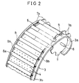
- numeral 3 denotes a guide member which is fixed to each side of the side walls 2.
- This guide member 3 has a shape like a comma-shaped bead or a slightly deformed C-shape and is made up of an introducing portion 3a of a semicirculer section, a guide surface portion and a discontinuous portion 3d.
- the guide surface portion is made up of an arcuate section 3b whose radius of curvature is large (i.e., its curvature is small) and an arcuate section 3c whose radius of curvature is small (i.e., its curvature is large).
- This guide member 3 is provided on its entire surface with a large number of drain holes 4.
- Teeth 7a of a pair of restricting sprockets 7 which are fixed to a shaft 6 of the sprocket at the same phase are arranged to project beyond the narrow grooves 5.
- the shaft 6 of the sprocket 7 is rotatably supported on both side walls 2.
- the roller chain 8 is made into an endless chain having a large number of rollers 8a which are disposed in parallel with each other and are connected by links 8b so as to be rotatable and slightly movable in an axial direction of the roller 8a.
- the roller chain 8 is fitted into an outer periphery of the guide member 3 such that each roller 8a is moved while rotating on each of the arcuate sections 3b and 3c and is moved forwards by skipping the discontinuous portion 3d.
- the filter belts 9 are made up of an upper (or an outer as seen in connection with rotation) filter belt or cloth 9a and a lower (or inner as seen in connection with rotation) filter belt or cloth 9b.
- the sludge S which is fed onto the lower filer belt 9b is pinched under pressure between the lower filter belt 9b and the upper filter belt 9a.
- the dewatering operation is performed while the filter belts 9a, 9b make substantially one rotation around the guide member 3 on the roller chain 8 in the direction shown by an arrow A.
- the upper filter belt 9a and the lower filter belt 9b are respectively tracted by driving rollers 10, 11.
- both filter belts 9, 9b After dewatering in a combined operation of both filter belts 9, 9b, they are separated from each other after passing through a guide roller 12, thereby discharging the cake C, and are circulated by being guided by guide rollers 13 and guide (or restriction) rollers 15, 16.
- the guide roller 12 may also be constituted as a driving roller.
- the filter belts 9 to be tracted by the driving rollers 10, 11 move, after positioning by the guide (or restriction) rollers 15, 16, through a rolling operation or function of the rollers 8a from the arcuate section 3b of large radius of curvature towards the arcuate section 3c of smaller radius of curvature.
- a perpendicular force to be urged against the rollers 8a by the traction works or operates as a squeezing force, thereby squeezing the water content in the sludge S.
- the squeezed water partially flows either directly through the outer surfaces of the filter belts or along the rollers and is discharged partially through the discharge holes 4 and finally through a discharge outlet 20.
- the radius of curvature of the guide member 3 may be changed to further multiple stages, instead of the above-described two stages in the form of the above-described arcuate sections of 3b and 3c.
- the filter belts 9 are separated into the upper filter belt 9b and the lower filter belt 9a after passing through the guide roller 12.
- the residue or dewatered cake C is either freely dropped or scraped by a knife or a scraper 21.
- Sludge which remains adhered on the filter belts is washed with a spray 22.
- the filter belts 9a, 9b are guided or restricted by the guide (or restriction) rollers 15, 16 into a correct position and continue the squeezing operation by receiving the feeding of the new sludge S.
- the rolling force to be added from the filter belts 9 to the rollers 8a facilitates the movement of the filter belts 9 due to the roller function or rolling function.
- the roller chain 8 travels on the guide member 3 at one-half the speed of the filter belts 9 and, at the discontinuous portion 3d, reaches the introducing portion 3a by skipping it. Since there are provided a pair of sprockets 7 in the introducing portion 3a, each of the rollers 8a is engaged with teeth 7a of the right and the left sprockets 7. If one of the rollers 8a is inclined, it may be engaged with one of the teeth 7a but will remain out of contact with the other of the teeth 7a.
- roller 8a on the side of non-contact also moves down to the bottom of the teeth. Since both sprockets 7, 7 are in the name phase, the roller 8a in question becomes parallel with the shaft 6 of the sprockets 7, 7, thereby assuming a right position. As a result, the roller chain 8 can move on the guide member 3 in the correct locus.
- the guide member 3 is substantially in the shape of the comma-shaped bead in cross section. It may of course be possible to make it to a substantial polygon which is made up of alternately arranged sections of larger radius of curvature and smaller radius of curvature so as to vary the squeezing force to be operated on the filter belts In any case, however, it is necessary to provide a restricting sprocket 7 on an inner side or an outer side of the guide member 3 to thereby correct the posture of the roller chain 8. In addition, in case there is an excess or a shortage in the length of the roller chain 8 relative to the peripheral length of the guide member 3, the excess or shortage of the roller chain 8 can be adjusted by the positioning of the restricting sprocket 7.
- the restricting sprocket 7 a sprocket which has teeth whose width is large enough to correctly guide the roller chain 8, there can also be obtained a restricting function by the width of the teeth. Therefore, there may be provided only one sprocket in substantially the axially central portion of the roller 8a.
- the construction of the supporting member can be made simple, and the length of the guide member along which the roller chain travels can be made long. Further, there can be provided a section having a smaller radius of curvature. Therefore, the squeezing can be performed for a longer period of time and a higher pressure can be applied in the sections having a smaller radius of curvature. As a consequence, a higher rate of dewatering can be obtained.
- the excess or shortage of the roller chain can be adjusted by the restricting sprocket. Still furthermore, since the travelling direction of the roller chain is always restricted by the restricting sprocket, there will occur no askew travelling of the roller chain and, consequently, a smooth operation can be continued.
Landscapes
- Chemical & Material Sciences (AREA)
- Chemical Kinetics & Catalysis (AREA)
- Engineering & Computer Science (AREA)
- Mechanical Engineering (AREA)
- Treatment Of Sludge (AREA)
- Filtration Of Liquid (AREA)
Priority Applications (2)
| Application Number | Priority Date | Filing Date | Title |
|---|---|---|---|
| JP5033664A JPH0732846B2 (ja) | 1993-02-23 | 1993-02-23 | 濾布ベルト式脱水機 |
| EP94113207A EP0698480A1 (fr) | 1993-02-23 | 1994-08-24 | Dispositif d'essorage du type à bande filtrante |
Applications Claiming Priority (3)
| Application Number | Priority Date | Filing Date | Title |
|---|---|---|---|
| JP5033664A JPH0732846B2 (ja) | 1993-02-23 | 1993-02-23 | 濾布ベルト式脱水機 |
| EP94113207A EP0698480A1 (fr) | 1993-02-23 | 1994-08-24 | Dispositif d'essorage du type à bande filtrante |
| US08/493,473 US5656165A (en) | 1993-02-23 | 1995-06-22 | Dewatering apparatus of filter belt type |
Publications (1)
| Publication Number | Publication Date |
|---|---|
| EP0698480A1 true EP0698480A1 (fr) | 1996-02-28 |
Family
ID=27235860
Family Applications (1)
| Application Number | Title | Priority Date | Filing Date |
|---|---|---|---|
| EP94113207A Ceased EP0698480A1 (fr) | 1993-02-23 | 1994-08-24 | Dispositif d'essorage du type à bande filtrante |
Country Status (2)
| Country | Link |
|---|---|
| EP (1) | EP0698480A1 (fr) |
| JP (1) | JPH0732846B2 (fr) |
Cited By (1)
| Publication number | Priority date | Publication date | Assignee | Title |
|---|---|---|---|---|
| EP0920896A1 (fr) * | 1997-12-03 | 1999-06-09 | Voith Sulzer Papiertechnik Patent GmbH | Procédé de déshydration d'une suspension fibreuse |
Families Citing this family (1)
| Publication number | Priority date | Publication date | Assignee | Title |
|---|---|---|---|---|
| US5656165A (en) * | 1993-02-23 | 1997-08-12 | Yamamoto Kogyo Kabushiki Kaisha | Dewatering apparatus of filter belt type |
Citations (5)
| Publication number | Priority date | Publication date | Assignee | Title |
|---|---|---|---|---|
| DE1786320A1 (de) * | 1968-09-17 | 1972-01-05 | Rawi Bedrijfsmechanisatie N V | Wasserreinigungsanordnung |
| GB2051598A (en) * | 1979-05-17 | 1981-01-21 | Wickham & Co Ltd D | Apparatus for dewatering sludges |
| EP0155658A2 (fr) * | 1984-03-23 | 1985-09-25 | Alb. Klein GmbH & Co. KG | Presse à double bande |
| JPS62224499A (ja) * | 1986-03-26 | 1987-10-02 | Ebara Infilco Co Ltd | 汚泥脱水装置の運転方法 |
| EP0311526A1 (fr) * | 1987-10-07 | 1989-04-12 | Guy Gaudfrin | Filtre-presse à toiles filtrantes sans fin |
-
1993
- 1993-02-23 JP JP5033664A patent/JPH0732846B2/ja not_active Expired - Lifetime
-
1994
- 1994-08-24 EP EP94113207A patent/EP0698480A1/fr not_active Ceased
Patent Citations (5)
| Publication number | Priority date | Publication date | Assignee | Title |
|---|---|---|---|---|
| DE1786320A1 (de) * | 1968-09-17 | 1972-01-05 | Rawi Bedrijfsmechanisatie N V | Wasserreinigungsanordnung |
| GB2051598A (en) * | 1979-05-17 | 1981-01-21 | Wickham & Co Ltd D | Apparatus for dewatering sludges |
| EP0155658A2 (fr) * | 1984-03-23 | 1985-09-25 | Alb. Klein GmbH & Co. KG | Presse à double bande |
| JPS62224499A (ja) * | 1986-03-26 | 1987-10-02 | Ebara Infilco Co Ltd | 汚泥脱水装置の運転方法 |
| EP0311526A1 (fr) * | 1987-10-07 | 1989-04-12 | Guy Gaudfrin | Filtre-presse à toiles filtrantes sans fin |
Non-Patent Citations (1)
| Title |
|---|
| PATENT ABSTRACTS OF JAPAN vol. 12, no. 83 (M - 677)<2930> 16 March 1988 (1988-03-16) * |
Cited By (2)
| Publication number | Priority date | Publication date | Assignee | Title |
|---|---|---|---|---|
| EP0920896A1 (fr) * | 1997-12-03 | 1999-06-09 | Voith Sulzer Papiertechnik Patent GmbH | Procédé de déshydration d'une suspension fibreuse |
| US6143133A (en) * | 1997-12-03 | 2000-11-07 | Voith Sulzer Papiertechnik Patent Gmbh | Method and device for drainage of a fibrous suspension |
Also Published As
| Publication number | Publication date |
|---|---|
| JPH06246111A (ja) | 1994-09-06 |
| JPH0732846B2 (ja) | 1995-04-12 |
Similar Documents
| Publication | Publication Date | Title |
|---|---|---|
| US5549195A (en) | Movable surface with articulated plates | |
| US5656165A (en) | Dewatering apparatus of filter belt type | |
| DE112011105280B4 (de) | Polygon-Kompensationskopplung für ketten- und zahnradgetriebene Systeme | |
| CA2220719C (fr) | Machine a emballer | |
| GB1575327A (en) | Drive unit for an endless conveyor | |
| US4887708A (en) | Drive apparatus for belt power turns | |
| CN101460765A (zh) | 导能链 | |
| EP0698480A1 (fr) | Dispositif d'essorage du type à bande filtrante | |
| FI62000C (fi) | Filterpress foer avvattning av avlopps- eller konditioneringsslam | |
| EP0020148A1 (fr) | Transporteurs et élévateurs du type à godets | |
| CA1320146C (fr) | Filtre-presse a bandes-filtres sans fin | |
| KR19990008060A (ko) | 컨베이어용 팰릿 | |
| WO1995030610A1 (fr) | Installations d'acheminement | |
| DE2504696C3 (de) | Kettenspannvorrichtung für kettenbetriebene Arbeitsmaschinen, insbesondere im Bergbau | |
| US4142461A (en) | Device for dewatering sludge and other material containing water and solid particles | |
| WO2004089789A1 (fr) | Dispositif d'appoint pour convoyeur a courroie tubulaire et convoyeur a courroie tubulaire equipe dudit dispositif | |
| DE2424435C2 (de) | Zwischenantrieb für ein Förderband | |
| JPS62230499A (ja) | 汚泥脱水装置の運転方法 | |
| CA2260507A1 (fr) | Chaine de transporteur a accumulation a friction controlee | |
| US4410080A (en) | Delivery device for a freezing plant | |
| DE2752936A1 (de) | Doppelmittelkettenfoerderer | |
| JPH078326B2 (ja) | 回転ドラム式脱水装置 | |
| GB2048136A (en) | Apparatus and method for reforming round cans into rectangular cans | |
| EP0391017B1 (fr) | Appareil pour mettre la pâte en boule | |
| DE10243117B4 (de) | Förderbahn für Stückgut, insbesondere für Gepäck-Behälter |
Legal Events
| Date | Code | Title | Description |
|---|---|---|---|
| PUAI | Public reference made under article 153(3) epc to a published international application that has entered the european phase |
Free format text: ORIGINAL CODE: 0009012 |
|
| AK | Designated contracting states |
Kind code of ref document: A1 Designated state(s): BE DE FR GB IT SE |
|
| 17P | Request for examination filed |
Effective date: 19960807 |
|
| 17Q | First examination report despatched |
Effective date: 19980612 |
|
| GRAG | Despatch of communication of intention to grant |
Free format text: ORIGINAL CODE: EPIDOS AGRA |
|
| STAA | Information on the status of an ep patent application or granted ep patent |
Free format text: STATUS: THE APPLICATION HAS BEEN REFUSED |
|
| 18R | Application refused |
Effective date: 19991204 |