EP0920896A1 - Procédé de déshydration d'une suspension fibreuse - Google Patents
Procédé de déshydration d'une suspension fibreuse Download PDFInfo
- Publication number
- EP0920896A1 EP0920896A1 EP98118686A EP98118686A EP0920896A1 EP 0920896 A1 EP0920896 A1 EP 0920896A1 EP 98118686 A EP98118686 A EP 98118686A EP 98118686 A EP98118686 A EP 98118686A EP 0920896 A1 EP0920896 A1 EP 0920896A1
- Authority
- EP
- European Patent Office
- Prior art keywords
- layer
- suspension
- zone
- water
- water extraction
- Prior art date
- Legal status (The legal status is an assumption and is not a legal conclusion. Google has not performed a legal analysis and makes no representation as to the accuracy of the status listed.)
- Withdrawn
Links
- 239000000725 suspension Substances 0.000 title claims abstract description 54
- 239000000835 fiber Substances 0.000 title claims abstract description 34
- 238000000034 method Methods 0.000 title claims description 55
- XLYOFNOQVPJJNP-UHFFFAOYSA-N water Substances O XLYOFNOQVPJJNP-UHFFFAOYSA-N 0.000 claims abstract description 17
- 239000007787 solid Substances 0.000 claims abstract description 8
- 230000003247 decreasing effect Effects 0.000 claims abstract description 3
- 239000000706 filtrate Substances 0.000 claims description 28
- 230000000694 effects Effects 0.000 claims description 8
- 239000002657 fibrous material Substances 0.000 claims description 5
- 239000004809 Teflon Substances 0.000 claims description 2
- 229920006362 Teflon® Polymers 0.000 claims description 2
- 230000032258 transport Effects 0.000 claims 2
- 230000000717 retained effect Effects 0.000 claims 1
- 238000003809 water extraction Methods 0.000 abstract 9
- 230000003068 static effect Effects 0.000 abstract 1
- 238000005406 washing Methods 0.000 description 6
- 230000007423 decrease Effects 0.000 description 4
- 239000004744 fabric Substances 0.000 description 4
- 239000000463 material Substances 0.000 description 4
- 230000002349 favourable effect Effects 0.000 description 3
- 239000007788 liquid Substances 0.000 description 3
- 238000007789 sealing Methods 0.000 description 3
- 230000015572 biosynthetic process Effects 0.000 description 2
- 239000012634 fragment Substances 0.000 description 2
- 238000000926 separation method Methods 0.000 description 2
- 241000294754 Macroptilium atropurpureum Species 0.000 description 1
- 239000000919 ceramic Substances 0.000 description 1
- 239000011248 coating agent Substances 0.000 description 1
- 238000000576 coating method Methods 0.000 description 1
- 238000011109 contamination Methods 0.000 description 1
- 238000010586 diagram Methods 0.000 description 1
- 229910003480 inorganic solid Inorganic materials 0.000 description 1
- 230000003993 interaction Effects 0.000 description 1
- 238000005461 lubrication Methods 0.000 description 1
- 230000014759 maintenance of location Effects 0.000 description 1
- 230000007246 mechanism Effects 0.000 description 1
- 238000010327 methods by industry Methods 0.000 description 1
- 239000000203 mixture Substances 0.000 description 1
- 239000002245 particle Substances 0.000 description 1
- 238000004064 recycling Methods 0.000 description 1
- 230000002940 repellent Effects 0.000 description 1
- 239000005871 repellent Substances 0.000 description 1
- 230000000630 rising effect Effects 0.000 description 1
- 239000007858 starting material Substances 0.000 description 1
- 239000000126 substance Substances 0.000 description 1
Images



Classifications
-
- B—PERFORMING OPERATIONS; TRANSPORTING
- B01—PHYSICAL OR CHEMICAL PROCESSES OR APPARATUS IN GENERAL
- B01D—SEPARATION
- B01D33/00—Filters with filtering elements which move during the filtering operation
- B01D33/04—Filters with filtering elements which move during the filtering operation with filtering bands or the like supported on cylinders which are impervious for filtering
-
- B—PERFORMING OPERATIONS; TRANSPORTING
- B01—PHYSICAL OR CHEMICAL PROCESSES OR APPARATUS IN GENERAL
- B01D—SEPARATION
- B01D33/00—Filters with filtering elements which move during the filtering operation
- B01D33/58—Handling the filter cake in the filter for purposes other than for regenerating the filter cake remaining on the filtering element
- B01D33/62—Handling the filter cake in the filter for purposes other than for regenerating the filter cake remaining on the filtering element for drying
- B01D33/64—Handling the filter cake in the filter for purposes other than for regenerating the filter cake remaining on the filtering element for drying by compression
Definitions
- the invention relates to a method for dewatering a fiber suspension according to the preamble of claim 1.
- washing processes are more or less strongly interconnected, because is for washing a fiber suspension dewatering is of course necessary. Washing processes are mostly relative low initial material densities (0.5 - 3%). The extent of the washing effect depends on other parameters, not just the increase in consistency.
- Methods for dewatering can be carried out with various known devices for Dewatering of a fiber suspension can be carried out. The most important are Various types of screen presses and filter presses.
- the fiber suspension is between a screen and a Roller or inserted between two sieves and compressed so that part of the Water leaks.
- the suspension is either imported by a Cloth box from which the suspension runs into the area of the sieve or sieves or through a headbox that forms a free jet.
- the fabric box can not with too thin fabric densities Suspension are used. Then a headbox is required.
- Drainage processes are known, e.g. from WO 96/08600, in which whole deliberate frictional forces are generated between two surfaces moving relative to each other, which are so large that roll formation of the thickened fiber material occurs. Vacuum is applied to support this effect. Such procedures are the first to be carried out reliably at higher consistencies.
- the invention has for its object to a method of the type mentioned find and design such that even with a simple device a high Drainage performance is achieved.
- the surface can advantageously be very smooth, e.g. be polished. It's also a repellent and / or anti-friction coating, such as. Teflon or ceramic, an advantage.
- the method according to the invention offers the possibility of a Part of the filtrate already obtained in the fiber.
- this will known filtrate recycling made possible in a particularly advantageous manner, namely by adding on the opposite side of the permeable surface already formed layer.
- An addition point can be selected for the filtrate, where the fibrous layer already has a certain filter effect for the applied Can provide filtrate.
- the filtrate must first penetrate the layer before it can emerge again. In this way through the layer, just those desired components of the returned filtrate. It has shown that the 1st filtrate is also a relatively large one in addition to the inorganic solids Contains amount of organic. These are especially the fine fibers and Fiber fragments that contribute to sheet strength.
- these substances come to a place already thickened fibrous layer from which the water first flows through it before the permeable surface, e.g. the sieve.
- the remain Fiber fragments depend on their size and affinity for the rest of the fiber, so no longer go into the filtrate.
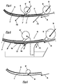
- Fig. 1 essentially shows the first surface 1 and the second surface 2, these Surfaces are arranged so that a converging drainage gap 5 with a curved drainage zone 6 forms. Areas 1 and 2 are in side view indicated.
- the first surface 1 lies on an only partially drawn endless one Screen belt.
- the second surface 2 stands still while the Sieve belt 4 is moved in the direction of movement A relative to the second surface 2.
- T, T ' Screen tension
- the screen belt 4 against a curved surface, here the second surface 2 pressed. This creates a between the two surfaces 1 and 2 Pressure with which the fiber suspension can be dewatered.
- the Drainage is supported here by centrifugal force, since it takes place radially outwards.
- the second surface 2 is designed so that the pressed against it first surface 1 a shape with different radii of curvature R1, R2, R3 occupies.
- the radii of curvature decrease in the direction of movement A, i.e. the Curvature gets stronger.
- the pressure between the surfaces decreases with decreasing Radius of curvature too.
- the relatively large initial radius of curvature R1 results in a gentle fleece formation, which ensures the desired retention of the fibrous materials is improved.
- Fibrous suspension S e.g. in the form of a flat jet, injected. Because the first Surface 1 is permeable to water, filtrate F1, F2, F3 passes through it. The remaining fiber suspension is thickened so that a layer 7 is formed, which is transported on the first surface 1.
- the figures show the Size ratios not to scale. It should only be the necessary Make steps clear when carrying out the method according to the invention.
- FIG. 2 goes into the conditions in the process diagram of FIG. 1 in somewhat more detail on.
- Fibrous suspension S is shown schematically in its various stages.
- Man recognizes a layer 7, which is located on the first surface 1 and from this in Direction of movement A is transported.
- This layer 7 has already been dewatered that it has a certain structure.
- the invention offers the possibility of working in multiple layers with simple means, by, as FIG. 3 shows, further suspension S 'through a further headbox 9' is added. This can preferably be done in the drainage zone 6 through the second happen through area 2. According to FIG. 3, the choice is made accordingly Operating parameters the further fiber suspension S 'directly into the low viscosity Suspension layer 7 'initiated, in such a way that the layer 7 already formed is not is torn open. As already mentioned, the first can be an advantage at this point Filtrate F1 are returned to the fibrous layer. This driving style increases the Yield and demands the selectivity of the laundry.
- the pressure drop (according to Bernoulli) in the range of Flow expansion should be so strong that the liquid in the headbox 9 'is not must be pumped in, but is sucked in automatically. That can be an advantage be if e.g. at this point the first filtrate collected in the open filtrate container F1 should be fed again. It may be useful to use the water-permeable Surface, so here the sieve belt 4 to attach a sealing device 17 so that it Sucking in air or sucking back water into the fiber layer prevented.
- This sealing device can be a flexible impermeable band 18 contain.
- the inflow point can also be provided with an adjustable flap 8 with which the flow and pressure conditions can be influenced.
- a drainage device is shown in simplified form in FIG the method according to the invention can be carried out.
- this device is the second surface on a curved slide shoe 10, which here in a substantially horizontal position is fixed.
- the first area belongs to that revolving sieve belt 4 and by tensioning devices, not shown here pressed against the shoe 10 below.
- the suspension S passes through a Headbox 9 in the converging drainage gap 5.
- the Drainage zone 6 is located between the sieve belt 4 and the sliding block 10. After the pulp suspension has passed the dewatering zone 6, it is removed from the Sieve belt 4 transported to a dewatering roller 11, on which it due to the screen tension generated pressure is further dewatered.
- the radius of curvature of the dewatering roller 11 is smaller than the radius of curvature of the sliding block 10 because this increases the drainage pressure further can.
- the thickened fiber suspension stick to the dewatering roller 11 is by a scraper 13 removed from this and with a discharge device 14 from the Device removed.
- the dewatering roller 11 generally runs with the screen belt 4 with or drives it, but it can also have a relative speed to the sieve belt have, in particular, are certain.
- the water that is printed out as intended from the pulp suspension arrives as Filtrate in appropriate collection points, four in the case shown here Different filtrate qualities F1 to F4 can be obtained. If the filtrate is not or is only thrown off insufficiently, wipers 15 against the running sieve belt 4 can be employed. The type of division into different filtrate qualities remains Reserved by a specialist and depends on the requirements for the process. Man in this device also recognizes a second headbox 9 'arranged in this way is that from it through the shoe 10 through either further suspension or a filtrate, e.g. the first filtrate F1, are introduced into the drainage zone 6 can.
- a filtrate e.g. the first filtrate F1
- Fig. 8 shows the part of an apparatus for performing the method in which the Direction of movement A has a substantially downward course. At a Such an arrangement is the addition of the suspension S in the dewatering zone 6 facilitated. The self-suction from the first filtrate F1 can also be mentioned enable particularly easily. The thickened suspension is here without further Pressing removed from the sieve belt 4.
- FIG. 9 Another flow guidance is shown in FIG. 9.
- the filtrate F1 and F2 enters Collection container 16, which are located above the drainage zone. In the Filtrate discharge may be necessary.
- This device also contains a third headbox 9 ''. This enables a higher throughput.
- the device for carrying out the method according to FIG. 10 contains a relative one long area in which the sieve belt 4 is pressed against a sliding block 10, which in this case is resiliently supported.
- the dewatering zone 6 thus formed begins with a rising part followed and set by a substantially horizontal area continues until the course of the sieve belt is almost completely deflected. Then it runs back to the deflection roller 19, on which dewatered further due to the fabric tension becomes. If it is also used as a drive roller, a counter roller 20 be appropriate. Then the screen tension can be kept low if necessary, and blockage in the relatively long drainage zone is avoided.
- Radius of curvature decreases considerably in the direction of movement A, which - as already mentioned - the drainage pressure gradually increases. It is an advantage Radius of the deflection roller 19 is smaller than the minimum radius of curvature on the sliding block 10th
- Figures 1 to 10 show such shapes of the second surface 2, in which the Constantly decrease the radii of curvature, viewed in the direction of movement A.
- the variant according to FIG. 11 is provided with a constant radius of curvature R, designed as a cylindrical surface. This allows the device to continue simplify; the drainage effect sets in faster.
Landscapes
- Chemical & Material Sciences (AREA)
- Chemical Kinetics & Catalysis (AREA)
- Paper (AREA)
- Filtration Of Liquid (AREA)
Applications Claiming Priority (2)
| Application Number | Priority Date | Filing Date | Title |
|---|---|---|---|
| DE19753604A DE19753604C2 (de) | 1997-12-03 | 1997-12-03 | Verfahren zum Entwässern einer Faserstoffsuspension |
| DE19753604 | 1997-12-03 |
Publications (1)
| Publication Number | Publication Date |
|---|---|
| EP0920896A1 true EP0920896A1 (fr) | 1999-06-09 |
Family
ID=7850601
Family Applications (1)
| Application Number | Title | Priority Date | Filing Date |
|---|---|---|---|
| EP98118686A Withdrawn EP0920896A1 (fr) | 1997-12-03 | 1998-10-02 | Procédé de déshydration d'une suspension fibreuse |
Country Status (3)
| Country | Link |
|---|---|
| US (1) | US6143133A (fr) |
| EP (1) | EP0920896A1 (fr) |
| DE (1) | DE19753604C2 (fr) |
Cited By (1)
| Publication number | Priority date | Publication date | Assignee | Title |
|---|---|---|---|---|
| EP1967245A1 (fr) * | 2007-02-14 | 2008-09-10 | Levitronix LLC | Unité de pompe-filtre, dispositif de pompe-filtre doté d'une telle unité tout comme procédé destiné à l'exfiltration |
Families Citing this family (3)
| Publication number | Priority date | Publication date | Assignee | Title |
|---|---|---|---|---|
| DE19806402A1 (de) * | 1998-02-17 | 1999-08-19 | Voith Sulzer Papiertech Patent | Verfahren zum Zusammenführen zweier Suspensionsschichten sowie Eindickvorrichtung |
| WO2010104867A1 (fr) * | 2009-03-09 | 2010-09-16 | Univenture | Procédé et appareil pour séparer des particules d'un liquide |
| WO2016208459A1 (fr) * | 2015-06-22 | 2016-12-29 | 株式会社村田製作所 | Dispositif de filtration, procédé de filtration, et filtre de filtration |
Citations (6)
| Publication number | Priority date | Publication date | Assignee | Title |
|---|---|---|---|---|
| GB2051598A (en) * | 1979-05-17 | 1981-01-21 | Wickham & Co Ltd D | Apparatus for dewatering sludges |
| JPS6049894A (ja) * | 1983-08-29 | 1985-03-19 | Toray Ind Inc | 固液分離方法 |
| US4879034A (en) * | 1984-03-23 | 1989-11-07 | Alb. Klein Gmbh & Co. Kg | Dewatering device with two filtering belts |
| JPH0649894A (ja) * | 1992-06-09 | 1994-02-22 | Kosai Kin | 鋼角管構造壁板枠耐力型組立式建築 |
| WO1995030046A1 (fr) * | 1994-05-03 | 1995-11-09 | Kvaerner Pulping Technologies Ab | Procede de traitement d'un materiau fibreux a teneur en liquide et appareil de mise en application du procede |
| EP0698480A1 (fr) * | 1993-02-23 | 1996-02-28 | Yamamoto Kogyo Kabushiki Kaisha | Dispositif d'essorage du type à bande filtrante |
Family Cites Families (15)
| Publication number | Priority date | Publication date | Assignee | Title |
|---|---|---|---|---|
| US36297A (en) * | 1862-08-26 | Improvement in baling-pressej | ||
| CH644414A5 (de) * | 1980-02-06 | 1984-07-31 | Escher Wyss Gmbh | Siebmaschine, insbesondere zur behandlung von aus altpapier gewonnenen waesserigen faserstoffsuspensionen. |
| US4722793A (en) * | 1986-07-03 | 1988-02-02 | The Black Clawson Company | Apparatus and method for thickening pulp and paper stock |
| US4886005A (en) * | 1987-12-03 | 1989-12-12 | Atlanta Attachment Company | Thread undercut attachment for a multi-needle sewing machine |
| US5186791A (en) * | 1988-10-28 | 1993-02-16 | The Black Clawson Company | Apparatus for thickening pulp and paper stock |
| EP0376446A3 (fr) * | 1988-11-30 | 1991-04-17 | The Black Clawson Company | Epaississeur à 3 rouleaux pour pâte à papier et son utilisation |
| FI86963C (fi) | 1989-07-06 | 1992-11-10 | Ahlstroem Oy | Anordning och foerfarande foer behandling av massa |
| US5133832A (en) * | 1991-07-08 | 1992-07-28 | The Black Clawson Company | Process and system for preparation of waste paper stock with short and long fiber fractionation |
| DE4304908A1 (de) * | 1993-02-18 | 1994-06-23 | Voith Gmbh J M | Entwässerungseinrichtung |
| US5656165A (en) * | 1993-02-23 | 1997-08-12 | Yamamoto Kogyo Kabushiki Kaisha | Dewatering apparatus of filter belt type |
| DE4341580C1 (de) * | 1993-12-07 | 1995-02-16 | Bellmer Gmbh & Co Kg Geb | Vorrichtung zur Entwässerung von Suspensionen |
| SE503543C2 (sv) * | 1994-09-14 | 1996-07-01 | Kvaerner Hymac As | Förfarande och anordning för koncentrering av en fibersuspension |
| US5599426A (en) * | 1994-10-11 | 1997-02-04 | Hoffman Environmental Systems, Inc. | Method of washing pulp using a single endless support fabric |
| DE19648771C2 (de) * | 1996-08-30 | 1999-10-14 | Voith Sulzer Stoffaufbereitung | Verfahren und Vorrichtung zum Entwässern einer Faserstoffsuspension mit intensiver Entwässerung |
| DE19648773A1 (de) * | 1996-08-30 | 1998-03-05 | Voith Sulzer Stoffaufbereitung | Verfahren und Vorrichtungen zum Entwässern einer Faserstoffsuspension |
-
1997
- 1997-12-03 DE DE19753604A patent/DE19753604C2/de not_active Expired - Fee Related
-
1998
- 1998-10-02 EP EP98118686A patent/EP0920896A1/fr not_active Withdrawn
- 1998-11-24 US US09/198,459 patent/US6143133A/en not_active Expired - Fee Related
Patent Citations (6)
| Publication number | Priority date | Publication date | Assignee | Title |
|---|---|---|---|---|
| GB2051598A (en) * | 1979-05-17 | 1981-01-21 | Wickham & Co Ltd D | Apparatus for dewatering sludges |
| JPS6049894A (ja) * | 1983-08-29 | 1985-03-19 | Toray Ind Inc | 固液分離方法 |
| US4879034A (en) * | 1984-03-23 | 1989-11-07 | Alb. Klein Gmbh & Co. Kg | Dewatering device with two filtering belts |
| JPH0649894A (ja) * | 1992-06-09 | 1994-02-22 | Kosai Kin | 鋼角管構造壁板枠耐力型組立式建築 |
| EP0698480A1 (fr) * | 1993-02-23 | 1996-02-28 | Yamamoto Kogyo Kabushiki Kaisha | Dispositif d'essorage du type à bande filtrante |
| WO1995030046A1 (fr) * | 1994-05-03 | 1995-11-09 | Kvaerner Pulping Technologies Ab | Procede de traitement d'un materiau fibreux a teneur en liquide et appareil de mise en application du procede |
Non-Patent Citations (1)
| Title |
|---|
| PATENT ABSTRACTS OF JAPAN vol. 009, no. 179 (M - 399) 24 July 1985 (1985-07-24) * |
Cited By (2)
| Publication number | Priority date | Publication date | Assignee | Title |
|---|---|---|---|---|
| EP1967245A1 (fr) * | 2007-02-14 | 2008-09-10 | Levitronix LLC | Unité de pompe-filtre, dispositif de pompe-filtre doté d'une telle unité tout comme procédé destiné à l'exfiltration |
| US8349172B2 (en) | 2007-02-14 | 2013-01-08 | Levitronix Technologies, LLC | Filter and pump unit, filter and pump apparatus having such a unit and also method for filtering out |
Also Published As
| Publication number | Publication date |
|---|---|
| DE19753604A1 (de) | 1999-06-10 |
| DE19753604C2 (de) | 1999-12-16 |
| US6143133A (en) | 2000-11-07 |
Similar Documents
| Publication | Publication Date | Title |
|---|---|---|
| DE3328162A1 (de) | Papiermaschine | |
| DE4102356C1 (fr) | ||
| AT400857B (de) | Maschine zur herstellung einer faserstoffbahn | |
| DE2716583A1 (de) | Verfahren und vorrichtung zum loesen der bahn vom formungssieb in einer papiermaschine und zum leiten der bahn in den pressenteil der papiermaschine | |
| DE2627102A1 (de) | Verfahren und vorrichtung zur bildung einer faserbahn | |
| EP0831174B1 (fr) | Procédé et dispositif pour la déshydratation d'une suspension fibreuse | |
| DE19753604C2 (de) | Verfahren zum Entwässern einer Faserstoffsuspension | |
| DE1147470B (de) | Vorrichtung zum Herstellen von Bahnen aus Papier, Pappe od. dgl. | |
| DE69716027T2 (de) | Verfahren und anordnung zur verhinderung der wiederbefeuchtung der bahn in einer nasspartie | |
| DE2000661C3 (de) | Bahnbildungszone einer Papiermaschine | |
| DE3014321A1 (de) | Papiermaschine mit einem siebzylinder | |
| DE2051444A1 (de) | Verfahren und Einrichtung zur Her stellung von Faserbahnen | |
| DE3222428A1 (de) | Doppelsieb-papiermaschine | |
| DE3532458C2 (fr) | ||
| EP0803604B1 (fr) | Presse humide | |
| DE4443874A1 (de) | Verfahren zur Entwässerung einer Papierfaserstoffschicht in einem Doppelsieb-Former und Vorrichtung zu seiner Durchführung | |
| EP0863253B1 (fr) | Procédé pour épaissir une suspension de fibres | |
| DE2100964A1 (de) | Vorrichtung zur Herstellung von Faser bahnen in einer Papiermaschine | |
| WO1999040994A1 (fr) | Epaississeur | |
| DE2826158A1 (de) | Verfahren und maschine zur herstellung von faserbahnen | |
| DE9207656U1 (de) | Maschine zur Herstellung einer Faserstoffbahn | |
| DE4026339C2 (de) | Spezialband für eine Entwässerungspresse einer Papiermaschine | |
| DE4105803A1 (de) | Entwaesserungseinrichtung fuer suspensionen | |
| DE2061506A1 (de) | Vorrichtung zur Herstellung von Papier | |
| DE2647295A1 (de) | Papiermaschine |
Legal Events
| Date | Code | Title | Description |
|---|---|---|---|
| PUAI | Public reference made under article 153(3) epc to a published international application that has entered the european phase |
Free format text: ORIGINAL CODE: 0009012 |
|
| AK | Designated contracting states |
Kind code of ref document: A1 Designated state(s): AT DE FI FR GB IT |
|
| AX | Request for extension of the european patent |
Free format text: AL;LT;LV;MK;RO;SI |
|
| 17P | Request for examination filed |
Effective date: 19991209 |
|
| AKX | Designation fees paid |
Free format text: AT DE FI FR GB IT |
|
| RAP1 | Party data changed (applicant data changed or rights of an application transferred) |
Owner name: VOITH PAPER PATENT GMBH |
|
| 17Q | First examination report despatched |
Effective date: 20030514 |
|
| STAA | Information on the status of an ep patent application or granted ep patent |
Free format text: STATUS: THE APPLICATION HAS BEEN WITHDRAWN |
|
| 18W | Application withdrawn |
Effective date: 20040513 |