EP0698708B1 - Dispositif de verrouillage pour attacher un objet portatif à un objet fixe - Google Patents
Dispositif de verrouillage pour attacher un objet portatif à un objet fixe Download PDFInfo
- Publication number
- EP0698708B1 EP0698708B1 EP95202231A EP95202231A EP0698708B1 EP 0698708 B1 EP0698708 B1 EP 0698708B1 EP 95202231 A EP95202231 A EP 95202231A EP 95202231 A EP95202231 A EP 95202231A EP 0698708 B1 EP0698708 B1 EP 0698708B1
- Authority
- EP
- European Patent Office
- Prior art keywords
- portions
- recess
- members
- undercut
- rib
- Prior art date
- Legal status (The legal status is an assumption and is not a legal conclusion. Google has not performed a legal analysis and makes no representation as to the accuracy of the status listed.)
- Expired - Lifetime
Links
- 230000000295 complement effect Effects 0.000 claims abstract description 5
- 238000006073 displacement reaction Methods 0.000 claims description 6
- 238000003780 insertion Methods 0.000 claims description 6
- 230000037431 insertion Effects 0.000 claims description 6
- 230000000452 restraining effect Effects 0.000 claims description 4
- 239000003292 glue Substances 0.000 claims 1
- 230000007704 transition Effects 0.000 claims 1
- 238000000034 method Methods 0.000 description 2
- 229910000831 Steel Inorganic materials 0.000 description 1
- 238000004026 adhesive bonding Methods 0.000 description 1
- 230000013011 mating Effects 0.000 description 1
- 230000007246 mechanism Effects 0.000 description 1
- 238000012986 modification Methods 0.000 description 1
- 230000004048 modification Effects 0.000 description 1
- 239000010959 steel Substances 0.000 description 1
- 239000002023 wood Substances 0.000 description 1
Images




Classifications
-
- E—FIXED CONSTRUCTIONS
- E05—LOCKS; KEYS; WINDOW OR DOOR FITTINGS; SAFES
- E05B—LOCKS; ACCESSORIES THEREFOR; HANDCUFFS
- E05B73/00—Devices for locking portable objects against unauthorised removal; Miscellaneous locking devices
- E05B73/0082—Devices for locking portable objects against unauthorised removal; Miscellaneous locking devices for office machines, e.g. PC's, portable computers, typewriters, calculators
Definitions
- the present invention generally relates to locking devices and more particularly to an arrangement for safely connecting to each other a pair of objects so as to avoid the disconnection thereof.
- Known devices for the purposes in question usually comprise male and female profiled matching rails, such as of dove-tail cross-section equipped with suitable key locking mechanisms (see for example Swedish Patent No. 8400972-9).
- a locking device for arresting a portable object such as TV set, VCR or attache case to a stationary object comprising:
- Such a locking device is known from WO-A-9413913.
- the locking device according to the invention is further characterised in that said rib (22) and said recess (12) extend in the direction of free insertion of said rib (22) in said recess (12), such that the first and the second members (10, 20) are mutually engaged against relative transverse displacement, once inserted one into the other.
- the undercut portions are preferably of a circular profile.
- the locking device may be associated with steel cable or the like by which an additional portable object can be safely secured by one and the same locking device.
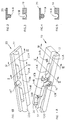
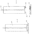
- Figs. 1a and 1b there is shown the first, bottom or female locking member denoted 10 being of generally elongated block shape of a rectangular cross-section. All along the block 10 there is formed a recess 12 having an undercut cross-section, in the illustrated example being of a more than half a circular cross-section. However, other undercut profiles may be used such as square, polygonal or dove-tail.
- the undercut recess 12 is interfered at two locations, namely by open-top portions 14a and 14b whereby the overhanging circular portions (above the horizontal diameter thereof) is cut away to form a U-shaped cross-section as shown in Fig. 5.
- the overhanging circular portions above the horizontal diameter thereof
- Fig. 5 There are thus formed three distanced undercut sub-portions namely 12a, 12b and 12c, separated by the two relieved, non-undercut portions 14a and 14b.
- a bore 16' with an enlarged portion 16'a for receiving a key-operated device for locking the pair of locking members together as will be explained further below.
- the upper, male block shaped locking member designated 20 it comprises a bulged rib 22 of a complementary cross-section (Fig. 4) namely slidingly fitting into the recess 12.
- the circular contour of the rib 22 is interfered by cut-away portions 24a and 24b (see Fig. 2).
- the distances and arrangement of the upper member 20 conforms that of the bottom member 10, namely that three male portions 22a, 22b and 22c are present with two relieved portions 24a and 24b.
- the member 20 is also provided with a complementary bore designated 16'' which, together with the bore 16' of the member 10, defines a cavity for a key operated locking device of any known design.
- the far end side of the member 10 is provided with an additional cavity 30 extended by an open-sided recess 32, which is used if a cable security arrangement is to be employed.
- a pair of bores 34a and 34b are formed for passing of screws by which the bottom locking member 10 can be mounted to the stationary object (not shown).
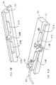
- Figs. 6a and 6b illustrate the manner of interlocking of the members 10 and 20 to each other. This is conveniently achieved by inserting the male portion 22c from above into the cavity portion 14b, the relieved portion 24b into the undercut portion 12b, the portion 22b into the cavity portion 14a, and the relieved portion 24a into the undercut portion 12a. After such interconnection, the member 20 can slide into complete overlapping along a short distance only -- which is considered as the main advantage relative to the situation where the members have to be engaged by sliding the upper member all along the bottom member which would have been the case but for the interchanging relieved and undercut arrangement of portions as described above.
- TV set 140 has attached thereto (preferably by gluing according to a procedure that will be described later) a pair of male locking blocks 120 at its two sides, whereas table or other support 142 has secured thereto bottom locking members 110, e.g. by wood screws 134 (Fig. 7c).
- Figs. 7c and 7d the TV set 140 with its locking members 120 is hold above the bottom locking members 110, inserted thereinto (Fig. 7e) and slide to its final position (Figs. 7f and 7g), then locked with an any suitable key operated locking unit 116.
- the following technique is proposed. First, the members 110 are affixed to the table 142. The members 120 are then engaged in the ultimate matching position, namely interlocked with and overlapping the members 110.
- a double-side sticking strip is applied to the top surface of the members 120, and the TV set placed thereon. It can then be disengaged, and the members 120 further secured by screws - if deemed necessary.
- a cable arrangement may be provided for the combined securement of an additional portable unit, such as VCR set 144.
- a cable 60 is affixed to the VCR unit 144 (see Fig. 7c) by any means such as a plate 162 and screws 164.
- the cable 160 extends upwardly and terminated with a cap 166 configured to be accommodated within the recess 30 (see Fig. 1a).
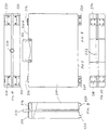
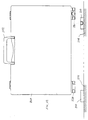
- Attache case 240 of Fig. 8 thus comprises two pairs of male lock members 220, engageable in a similar manner as before described with respect to the locking device 10 of the preceding embodiment, to female, fixed members 210 (Fig. 12).
- case 240 is preferably openable from its bottom side 240a, which is provided with lock 270, whereas its handle 272 and pair of hinges 274, 276 are located at its top side 240b. In this manner, the lock 270 is inaccessible and thus protected against tampering therewith.
Landscapes
- Engineering & Computer Science (AREA)
- Computer Hardware Design (AREA)
- Casings For Electric Apparatus (AREA)
- Lock And Its Accessories (AREA)
- Telephone Function (AREA)
- Connection Of Plates (AREA)
- Insertion Pins And Rivets (AREA)
- Clamps And Clips (AREA)
Claims (7)
- Dispositif de verrouillage pour immobiliser un objet portable tel qu'un téléviseur, magnétoscope ou attaché-case sur un objet stationnaire comprenant :CARACTERISE EN CE QUEun premier organe allongé (10) avec une rainure (12) longitudinale, la rainure ayant au moins une partie profilée coupée (12A, 12B, 12C) et au moins deux parties non coupées (14A, 14B) espacées ;un second organe allongé complémentaire avec une nervure en saillie (22) s'étendant longitudinalement, la nervure ayant au moins une partie (22A, 22D, 22C) pouvant coulisser sur les parties (12A, 12B, 12C) et au moins deux parties (24A, 24B) librement insérables dans lesdites parties non coupées (14A, 14B) du premier organe (10), arrangées dans la même disposition espacée ;de sorte que la nervure (22) dudit second organe (20) puisse être librement insérée dans ladite rainure (12) du premier organe (10) en position de recouvrement partiel des organes (10, 20) ce par quoi les parties coulissantes (22A, 22B, 22C) s'engagent dans les parties non coupées (14A, 14B) et les parties librement insérables (24A, 24B) s'engagent dans les parties coupées (12A, 12B, 12C) et ensuite peuvent être glissées dans ladite rainure (12) par un déplacement longitudinal dans une position de recouvrement de sorte que les parties coulissantes (22A, 22B, 22C) s'engagent avec les parties coupées (12A, 12B, 12C) et que lesdites parties librement insérables (24A, 24B) s'engagent avec les parties non coupées (14A, 14B) les premiers et second organes (10, 20) étant ainsi limités en déplacement mutuel dans une direction opposée à la direction d'insertion libre de la nervure (22) dans la rainure (12)les premier et second organes (10, 20) étant percés do troua (16', 16'A, 16") définissant une cavité dans ladite position de recouvrement des organes (10, 20) et des moyens de limitation adaptés à recevoir le moyen de verrouillage ; etdes moyens de verrouillage (16) pour bloquer les organes (10, 20) l'un sur l'autre contre leur glissement longitudinal à partir de ladite position de recouvrement, les moyens de verrouillage (16) étant insérés dans ladite cavité et maintenus par les moyens de maintien définis par les trous (16', 16'A, 16")
La nervure (22) et la rainure (12) s'étendent dans la direction de libre insertion de la nervure (22) dans la rainure (12) de sorte que les premier et second organes (10, 20) soient mutuellement bloqués contre un mouvement transversal relatif après insertion de l'un dans l'autre. - Dispositif selon la revendication 1 caractérisé en ce que la section transversale des parties coupées (12A, 12B, 12C) du premier organe (10) et des parties coulissantes (22A, 22B, 22C) du second organe est plus qu'à demi circulaire et que les sections transversales des parties non coupées (14A, 14B) du premier organe (10) et les parties librement insérables (24A, 24B) du second organe (20) sont en forme de "V", la largeur du "V" étant sensiblement égale au diamètre et à la partie ouverte de la section plus qu'à demi circulaire des parties coupées (12A, 12B, 12C) du premier organe (10).
- Dispositif selon la revendication 1 ou 2 caractérisé en ce que les transitions entre les parties respectives des premier et second organe (10, 20) sont chanfreinées pour que l'insertion libre de la nervure (22) soit guidée.
- Dispositif selon l'une quelconque des revendications précédentes dans lequel sont inclus dans le premier organe (10) trois parties coupées (12A, 12B, 12C) et deux parties non coupées (14A, 14B).
- Dispositif selon l'une quelconque des revendications précédentes dans lequel le premier organe (10) est adapté pour être fixé sur l'objet stationnaire et le second (20) sur l'objet portable.
- Dispositif selon la revendication 5 dans lequel le premier organe (10) est fixé sur l'objet stationnaire par des vis (134) et le second organe (20) par collage.
- Dispositif selon l'une quelconque des revendications précédentes dans lequel le premier organe (10) comprend une cavité (30) prolongée par une cavité à coté ouvert (32) et comprenant de plus un câble (60, 160) avec un embout (66, 166), insérables respectivement dans la cavité à côté ouvert (32) et dans la cavité (30), devenant verrouillé une fois que les premier et second organes (10, 20) sont en position de recouvrement.
Applications Claiming Priority (2)
| Application Number | Priority Date | Filing Date | Title |
|---|---|---|---|
| IL110720A IL110720A (en) | 1994-08-19 | 1994-08-19 | Locking device for fixing a portable object to a stationary object |
| IL11072094 | 1994-08-19 |
Publications (2)
| Publication Number | Publication Date |
|---|---|
| EP0698708A1 EP0698708A1 (fr) | 1996-02-28 |
| EP0698708B1 true EP0698708B1 (fr) | 2000-03-08 |
Family
ID=11066481
Family Applications (1)
| Application Number | Title | Priority Date | Filing Date |
|---|---|---|---|
| EP95202231A Expired - Lifetime EP0698708B1 (fr) | 1994-08-19 | 1995-08-17 | Dispositif de verrouillage pour attacher un objet portatif à un objet fixe |
Country Status (5)
| Country | Link |
|---|---|
| US (1) | US5601273A (fr) |
| EP (1) | EP0698708B1 (fr) |
| AT (1) | ATE190377T1 (fr) |
| DE (1) | DE69515399T2 (fr) |
| IL (1) | IL110720A (fr) |
Families Citing this family (6)
| Publication number | Priority date | Publication date | Assignee | Title |
|---|---|---|---|---|
| SE507315C2 (sv) * | 1992-12-09 | 1998-05-11 | Ulf Lundagaards | Låsanordning för att låsa ett föremål i förhållande till ett underlag |
| US6345874B2 (en) * | 1999-09-23 | 2002-02-12 | Avaya Technologies Corp. | Cabinet mounting structure |
| IL148661A0 (en) * | 2002-03-13 | 2002-09-12 | Avganim Mair | A locking arrangement of a portable article such as computer processor casing to a work surface |
| US20070119219A1 (en) * | 2005-08-22 | 2007-05-31 | Annette, Llc | Computer lock and corresponding security hole pattern |
| CN101290812B (zh) * | 2007-04-16 | 2010-05-26 | 明基电通股份有限公司 | 显示器及其卡固结构 |
| US10836304B2 (en) * | 2015-11-20 | 2020-11-17 | Ian Taberner | Security mounting arrangement |
Family Cites Families (12)
| Publication number | Priority date | Publication date | Assignee | Title |
|---|---|---|---|---|
| US3967476A (en) * | 1973-01-11 | 1976-07-06 | Look Robert A | Ski lock |
| DE2400124A1 (de) * | 1974-01-03 | 1975-07-10 | Guenter Noack | Ski-diebstahlsicherung |
| US4022036A (en) * | 1975-12-19 | 1977-05-10 | Cebuhar Stanley W | Tamperproof security device for equipment and method of protection |
| US4493267A (en) * | 1982-01-18 | 1985-01-15 | Jedziniak Francis J | Securable storage assembly for data processing device |
| US4496271A (en) * | 1982-09-30 | 1985-01-29 | East/West Industries, Inc. | Restraining fittings |
| GB2153902A (en) * | 1984-02-10 | 1985-08-29 | Ronald Michael Tipene | Securing devices |
| US4691891A (en) * | 1985-09-25 | 1987-09-08 | Robert Dionne | Device for preventing unauthorized removal of portable objects |
| US5076079A (en) * | 1990-01-22 | 1991-12-31 | Monoson David B | Anti-theft device for computers and the like |
| US5052651A (en) * | 1990-03-13 | 1991-10-01 | Mardesich Enterprises | Fastener for portable equipment |
| US5050836A (en) * | 1990-06-21 | 1991-09-24 | Makous Joseph M | Security device for portable equipment |
| US5228658A (en) * | 1992-03-02 | 1993-07-20 | Qualtec Data Products, Inc. | Equipment security apparatus |
| SE507315C2 (sv) * | 1992-12-09 | 1998-05-11 | Ulf Lundagaards | Låsanordning för att låsa ett föremål i förhållande till ett underlag |
-
1994
- 1994-08-19 IL IL110720A patent/IL110720A/xx not_active IP Right Cessation
-
1995
- 1995-08-16 US US08/515,814 patent/US5601273A/en not_active Expired - Lifetime
- 1995-08-17 DE DE69515399T patent/DE69515399T2/de not_active Expired - Lifetime
- 1995-08-17 AT AT95202231T patent/ATE190377T1/de active
- 1995-08-17 EP EP95202231A patent/EP0698708B1/fr not_active Expired - Lifetime
Also Published As
| Publication number | Publication date |
|---|---|
| IL110720A0 (en) | 1994-11-11 |
| IL110720A (en) | 1997-04-15 |
| US5601273A (en) | 1997-02-11 |
| ATE190377T1 (de) | 2000-03-15 |
| DE69515399D1 (de) | 2000-04-13 |
| DE69515399T2 (de) | 2000-10-19 |
| EP0698708A1 (fr) | 1996-02-28 |
Similar Documents
| Publication | Publication Date | Title |
|---|---|---|
| US5692722A (en) | Locking device | |
| US5022200A (en) | Interlocking sections for portable floors and the like | |
| US6128881A (en) | Portable floor | |
| US4988131A (en) | Interlocking sections for portable floors and the like | |
| US6619080B1 (en) | Lock bolt structure of steel cable lock | |
| US5217384A (en) | Mechanical locking on plug connection between electrical switch and connecting plug | |
| KR20010041994A (ko) | 고정 및 분리 시스템 | |
| EP0698708B1 (fr) | Dispositif de verrouillage pour attacher un objet portatif à un objet fixe | |
| HUT75438A (en) | Cylinder lock and a corresponding profiled key | |
| CA2191217A1 (fr) | Ensemble serrure a barre de verrouillage | |
| HK1002517A1 (en) | Door grip assembly | |
| EP0432167B1 (fr) | Elements d'assemblage pour planchers mobiles et analogues | |
| US7131300B1 (en) | Seal guard | |
| US2352190A (en) | Padlock | |
| US20030088954A1 (en) | Secure storage system for cremation urns | |
| CA1302671C (fr) | Charniere | |
| US20070234764A1 (en) | Hasps, Shackles and Padlocks | |
| US20240243520A1 (en) | Tamper resistant connector assembly | |
| JPH061030B2 (ja) | パネル外れ止め装置 | |
| EP1403532B1 (fr) | Dispositif de fixation d'articles sur un mur | |
| US4289343A (en) | Lock for slidable door | |
| JP3028488U (ja) | 防犯ケース | |
| GB2268959A (en) | Panel securing arrangement | |
| US20060099844A1 (en) | Plate locking systems for mated electrical connectors and methods thereof | |
| EP0499296A2 (fr) | Sections emboîtables pour planchers portables et semblable |
Legal Events
| Date | Code | Title | Description |
|---|---|---|---|
| PUAI | Public reference made under article 153(3) epc to a published international application that has entered the european phase |
Free format text: ORIGINAL CODE: 0009012 |
|
| AK | Designated contracting states |
Kind code of ref document: A1 Designated state(s): AT BE CH DE DK ES FR GB GR IE IT LI NL PT SE |
|
| 17P | Request for examination filed |
Effective date: 19960809 |
|
| 17Q | First examination report despatched |
Effective date: 19981013 |
|
| GRAG | Despatch of communication of intention to grant |
Free format text: ORIGINAL CODE: EPIDOS AGRA |
|
| GRAG | Despatch of communication of intention to grant |
Free format text: ORIGINAL CODE: EPIDOS AGRA |
|
| GRAH | Despatch of communication of intention to grant a patent |
Free format text: ORIGINAL CODE: EPIDOS IGRA |
|
| GRAH | Despatch of communication of intention to grant a patent |
Free format text: ORIGINAL CODE: EPIDOS IGRA |
|
| GRAA | (expected) grant |
Free format text: ORIGINAL CODE: 0009210 |
|
| AK | Designated contracting states |
Kind code of ref document: B1 Designated state(s): AT BE CH DE DK ES FR GB GR IE IT LI NL PT SE |
|
| PG25 | Lapsed in a contracting state [announced via postgrant information from national office to epo] |
Ref country code: SE Free format text: THE PATENT HAS BEEN ANNULLED BY A DECISION OF A NATIONAL AUTHORITY Effective date: 20000308 Ref country code: NL Free format text: LAPSE BECAUSE OF FAILURE TO SUBMIT A TRANSLATION OF THE DESCRIPTION OR TO PAY THE FEE WITHIN THE PRESCRIBED TIME-LIMIT Effective date: 20000308 Ref country code: LI Free format text: LAPSE BECAUSE OF NON-PAYMENT OF DUE FEES Effective date: 20000308 Ref country code: GR Free format text: LAPSE BECAUSE OF NON-PAYMENT OF DUE FEES Effective date: 20000308 Ref country code: ES Free format text: THE PATENT HAS BEEN ANNULLED BY A DECISION OF A NATIONAL AUTHORITY Effective date: 20000308 Ref country code: CH Free format text: LAPSE BECAUSE OF NON-PAYMENT OF DUE FEES Effective date: 20000308 Ref country code: BE Free format text: LAPSE BECAUSE OF FAILURE TO SUBMIT A TRANSLATION OF THE DESCRIPTION OR TO PAY THE FEE WITHIN THE PRESCRIBED TIME-LIMIT Effective date: 20000308 Ref country code: AT Free format text: LAPSE BECAUSE OF FAILURE TO SUBMIT A TRANSLATION OF THE DESCRIPTION OR TO PAY THE FEE WITHIN THE PRESCRIBED TIME-LIMIT Effective date: 20000308 |
|
| REF | Corresponds to: |
Ref document number: 190377 Country of ref document: AT Date of ref document: 20000315 Kind code of ref document: T |
|
| REG | Reference to a national code |
Ref country code: CH Ref legal event code: EP |
|
| REF | Corresponds to: |
Ref document number: 69515399 Country of ref document: DE Date of ref document: 20000413 |
|
| REG | Reference to a national code |
Ref country code: IE Ref legal event code: FG4D |
|
| ITF | It: translation for a ep patent filed | ||
| PG25 | Lapsed in a contracting state [announced via postgrant information from national office to epo] |
Ref country code: PT Free format text: LAPSE BECAUSE OF FAILURE TO SUBMIT A TRANSLATION OF THE DESCRIPTION OR TO PAY THE FEE WITHIN THE PRESCRIBED TIME-LIMIT Effective date: 20000608 Ref country code: DK Free format text: LAPSE BECAUSE OF FAILURE TO SUBMIT A TRANSLATION OF THE DESCRIPTION OR TO PAY THE FEE WITHIN THE PRESCRIBED TIME-LIMIT Effective date: 20000608 |
|
| ET | Fr: translation filed | ||
| NLV1 | Nl: lapsed or annulled due to failure to fulfill the requirements of art. 29p and 29m of the patents act | ||
| PG25 | Lapsed in a contracting state [announced via postgrant information from national office to epo] |
Ref country code: IE Free format text: LAPSE BECAUSE OF NON-PAYMENT OF DUE FEES Effective date: 20000817 |
|
| REG | Reference to a national code |
Ref country code: CH Ref legal event code: PL |
|
| PLBE | No opposition filed within time limit |
Free format text: ORIGINAL CODE: 0009261 |
|
| STAA | Information on the status of an ep patent application or granted ep patent |
Free format text: STATUS: NO OPPOSITION FILED WITHIN TIME LIMIT |
|
| 26N | No opposition filed | ||
| REG | Reference to a national code |
Ref country code: IE Ref legal event code: MM4A |
|
| REG | Reference to a national code |
Ref country code: GB Ref legal event code: IF02 |
|
| PG25 | Lapsed in a contracting state [announced via postgrant information from national office to epo] |
Ref country code: IT Free format text: LAPSE BECAUSE OF NON-PAYMENT OF DUE FEES;WARNING: LAPSES OF ITALIAN PATENTS WITH EFFECTIVE DATE BEFORE 2007 MAY HAVE OCCURRED AT ANY TIME BEFORE 2007. THE CORRECT EFFECTIVE DATE MAY BE DIFFERENT FROM THE ONE RECORDED. Effective date: 20050817 |
|
| PGFP | Annual fee paid to national office [announced via postgrant information from national office to epo] |
Ref country code: FR Payment date: 20090811 Year of fee payment: 15 |
|
| PGFP | Annual fee paid to national office [announced via postgrant information from national office to epo] |
Ref country code: GB Payment date: 20090807 Year of fee payment: 15 Ref country code: DE Payment date: 20090911 Year of fee payment: 15 |
|
| GBPC | Gb: european patent ceased through non-payment of renewal fee |
Effective date: 20100817 |
|
| REG | Reference to a national code |
Ref country code: FR Ref legal event code: ST Effective date: 20110502 |
|
| REG | Reference to a national code |
Ref country code: DE Ref legal event code: R119 Ref document number: 69515399 Country of ref document: DE Effective date: 20110301 |
|
| PG25 | Lapsed in a contracting state [announced via postgrant information from national office to epo] |
Ref country code: FR Free format text: LAPSE BECAUSE OF NON-PAYMENT OF DUE FEES Effective date: 20100831 Ref country code: DE Free format text: LAPSE BECAUSE OF NON-PAYMENT OF DUE FEES Effective date: 20110301 |
|
| PG25 | Lapsed in a contracting state [announced via postgrant information from national office to epo] |
Ref country code: GB Free format text: LAPSE BECAUSE OF NON-PAYMENT OF DUE FEES Effective date: 20100817 |