EP0699003A1 - Verfahren und vorrichtung zur bildsignalkodierung - Google Patents
Verfahren und vorrichtung zur bildsignalkodierung Download PDFInfo
- Publication number
- EP0699003A1 EP0699003A1 EP95908375A EP95908375A EP0699003A1 EP 0699003 A1 EP0699003 A1 EP 0699003A1 EP 95908375 A EP95908375 A EP 95908375A EP 95908375 A EP95908375 A EP 95908375A EP 0699003 A1 EP0699003 A1 EP 0699003A1
- Authority
- EP
- European Patent Office
- Prior art keywords
- data
- quantization
- image signal
- quantized
- quantization scale
- Prior art date
- Legal status (The legal status is an assumption and is not a legal conclusion. Google has not performed a legal analysis and makes no representation as to the accuracy of the status listed.)
- Withdrawn
Links
Images




Classifications
-
- H—ELECTRICITY
- H04—ELECTRIC COMMUNICATION TECHNIQUE
- H04N—PICTORIAL COMMUNICATION, e.g. TELEVISION
- H04N19/00—Methods or arrangements for coding, decoding, compressing or decompressing digital video signals
- H04N19/50—Methods or arrangements for coding, decoding, compressing or decompressing digital video signals using predictive coding
- H04N19/59—Methods or arrangements for coding, decoding, compressing or decompressing digital video signals using predictive coding involving spatial sub-sampling or interpolation, e.g. alteration of picture size or resolution
-
- H—ELECTRICITY
- H04—ELECTRIC COMMUNICATION TECHNIQUE
- H04N—PICTORIAL COMMUNICATION, e.g. TELEVISION
- H04N19/00—Methods or arrangements for coding, decoding, compressing or decompressing digital video signals
- H04N19/10—Methods or arrangements for coding, decoding, compressing or decompressing digital video signals using adaptive coding
- H04N19/102—Methods or arrangements for coding, decoding, compressing or decompressing digital video signals using adaptive coding characterised by the element, parameter or selection affected or controlled by the adaptive coding
- H04N19/124—Quantisation
- H04N19/126—Details of normalisation or weighting functions, e.g. normalisation matrices or variable uniform quantisers
-
- H—ELECTRICITY
- H04—ELECTRIC COMMUNICATION TECHNIQUE
- H04N—PICTORIAL COMMUNICATION, e.g. TELEVISION
- H04N19/00—Methods or arrangements for coding, decoding, compressing or decompressing digital video signals
- H04N19/10—Methods or arrangements for coding, decoding, compressing or decompressing digital video signals using adaptive coding
- H04N19/102—Methods or arrangements for coding, decoding, compressing or decompressing digital video signals using adaptive coding characterised by the element, parameter or selection affected or controlled by the adaptive coding
- H04N19/132—Sampling, masking or truncation of coding units, e.g. adaptive resampling, frame skipping, frame interpolation or high-frequency transform coefficient masking
-
- H—ELECTRICITY
- H04—ELECTRIC COMMUNICATION TECHNIQUE
- H04N—PICTORIAL COMMUNICATION, e.g. TELEVISION
- H04N19/00—Methods or arrangements for coding, decoding, compressing or decompressing digital video signals
- H04N19/10—Methods or arrangements for coding, decoding, compressing or decompressing digital video signals using adaptive coding
- H04N19/169—Methods or arrangements for coding, decoding, compressing or decompressing digital video signals using adaptive coding characterised by the coding unit, i.e. the structural portion or semantic portion of the video signal being the object or the subject of the adaptive coding
- H04N19/17—Methods or arrangements for coding, decoding, compressing or decompressing digital video signals using adaptive coding characterised by the coding unit, i.e. the structural portion or semantic portion of the video signal being the object or the subject of the adaptive coding the unit being an image region, e.g. an object
- H04N19/176—Methods or arrangements for coding, decoding, compressing or decompressing digital video signals using adaptive coding characterised by the coding unit, i.e. the structural portion or semantic portion of the video signal being the object or the subject of the adaptive coding the unit being an image region, e.g. an object the region being a block, e.g. a macroblock
-
- H—ELECTRICITY
- H04—ELECTRIC COMMUNICATION TECHNIQUE
- H04N—PICTORIAL COMMUNICATION, e.g. TELEVISION
- H04N19/00—Methods or arrangements for coding, decoding, compressing or decompressing digital video signals
- H04N19/10—Methods or arrangements for coding, decoding, compressing or decompressing digital video signals using adaptive coding
- H04N19/169—Methods or arrangements for coding, decoding, compressing or decompressing digital video signals using adaptive coding characterised by the coding unit, i.e. the structural portion or semantic portion of the video signal being the object or the subject of the adaptive coding
- H04N19/18—Methods or arrangements for coding, decoding, compressing or decompressing digital video signals using adaptive coding characterised by the coding unit, i.e. the structural portion or semantic portion of the video signal being the object or the subject of the adaptive coding the unit being a set of transform coefficients
-
- H—ELECTRICITY
- H04—ELECTRIC COMMUNICATION TECHNIQUE
- H04N—PICTORIAL COMMUNICATION, e.g. TELEVISION
- H04N19/00—Methods or arrangements for coding, decoding, compressing or decompressing digital video signals
- H04N19/10—Methods or arrangements for coding, decoding, compressing or decompressing digital video signals using adaptive coding
- H04N19/102—Methods or arrangements for coding, decoding, compressing or decompressing digital video signals using adaptive coding characterised by the element, parameter or selection affected or controlled by the adaptive coding
- H04N19/124—Quantisation
-
- H—ELECTRICITY
- H04—ELECTRIC COMMUNICATION TECHNIQUE
- H04N—PICTORIAL COMMUNICATION, e.g. TELEVISION
- H04N19/00—Methods or arrangements for coding, decoding, compressing or decompressing digital video signals
- H04N19/60—Methods or arrangements for coding, decoding, compressing or decompressing digital video signals using transform coding
Definitions
- This invention relates to an image signal encoding method and an image signal encoding apparatus used in various application fields such as digital storage media, television broadcasting, communication networks, and more particularly, this invention is applicable to an image signal encoding method and apparatus thereof for processing digitized motion picture sequence for transmission or storage in a compressed form.
- DCT discrete cosine transform
- the moving picture expert group employs a quantization method for quantizing the DCT coefficients in the transformed blocks so as to represent by a set of symbols with a manageable size.
- the DCT coefficient is divided by a constant "q" (hereinafter, referred to as "quantization scale”).
- quantization scale a constant
- each DCT coefficient is approximated to the nearest integer to the DCT coefficient (hereinafter, referred to as “quantized DCT coefficient").
- quantized DCT coefficient By doing the inverse operation by multiplying the quantized DCT coefficient by the quantization scale "q", It is possible to restore the DCT coefficient to that before coding.
- the picture to transform is a motion picture
- a typical characteristic of image signal is that there are a few changes between consecutive frames except for some motion of objects in the screen.
- a technique, commonly referred to as motion compensation is used.
- the current picture with blocks is represented by displacement vector taken from the previously coded pictures.
- the motion compensation scheme further reduces the number of bits needed to code the motion picture.
- the displacement of the blocks in some cases, may result in some visible sharp edges between displaced blocks. This is generally called as block noise.
- the moving picture expert group has employed such two mentioned schemes (discrete cosine transform and motion compensation) to respective schemes of MPEG1 and MPEG2 of the motion picture sequence coding standard.
- coding using motion compensation In practice, coding using motion compensation, coding using DCT/quantization, or coding using combination of both motion compensation and DCT/quantization are adaptively decided to each block.
- MPEG1 and MPEG2 have a rate control mechanism controlling the distribution of the number of bits for each block in the motion picture.
- the size of the quantization scale used in quantizer is set for each macro block corresponding to four DCT blocks, that is 16 x 16 pixels.
- the quantized DCT coefficients produced by the quantizer can be represented as the data composed of series of zero value followed by a non-zero value.
- Runlength coding can achieve significant data compression with redundant inputs characterized by long clusters of like symbols, so that the runlength coding is used in the MPEG1 and MPEG2 as the coding of the quantized DCT coefficients.
- a lower quantization scale will result in a shorter runs of zeros and more bits to encode the quantized DCT coefficients.
- the DCT coefficients having comparatively low energy do not give much effect to the picture quality, it is desirable to represent the quantized DCT coefficients by zero so as to heighten the coding efficiency.
- the DCT coefficients having comparatively high energy gives much effect to the picture quality, it is desirable to improve non-zero coefficients corresponding to the DCT coefficients having comparatively high energy without shortening the length of the runs of zeros of the quantized DCT coefficients.
- an object of the present invention is to provide an image signal encoding method and apparatus thereof capable of improving considerably the picture quality of video sequence comparing with the conventional ones.
- an image signal encoding method for encoding the image signal comprising the steps of: compressing dynamic ranges of image signal for each pixel; performing orthogonal transform on the image signal having compressed dynamic ranges for each unit block in order to transform the image signal to coefficient data; and quantizing the coefficient data to produce a quantized data.
- the image signal encoding method for encoding the image signal comprises the steps of: performing orthogonal transform on the image signal for each unit block in order to transform the image signal to coefficient data; quantizing the coefficient data based on a first quantization scale to produce a first quantized data; and quantizing the coefficient data, concerning only a coefficient data which has the first quantized data being non-zero, based on a second quantization scale which is smaller than the first quantization scale, to produce a second quantized data.
- an image signal decoding method for decoding the quantized data which is produced by compressing the dynamic ranges of image signal for each pixel, by performing the orthogonal transform on the image signal having the compressed dynamic ranges for each unit block to transform the image signal to the coefficient data, and by quantizing the coefficient data comprises the steps of: inverse-quantizing the quantized to produce the coefficient data; inverse-orthogonal-transforming the coefficient data for each unit block to produce the decoded picture, and extending the dynamic ranges of the decoded image signal for each pixel.
- the image signal encoding apparatus for encoding an image signal, comprising: dynamic range compressing means for compressing dynamic ranges of image signal for each pixel; orthogonal transforming means for orthogonal-transforming the image signal having compressed dynamic ranges for each block in order to transform it into coefficient data; and quantization means for quantizing the coefficient data to produce a quantized data.
- the image signal encoding apparatus for encoding image signal comprises: means for performing the orthogonal transform on image signal for each unit block to transform the image signal to coefficient data; first quantization means for quantizing the coefficient data based on a first quantization scale to produce a first quantized data; and second quantization means for quantizing the coefficient data, concerning only a coefficient data which has the first quantized data being non-zero practically, based on a second quantization scale which is smaller than the first quantization scale, to produce a second quantized data.
- an image signal decoding apparatus for decoding the quantized data which is produced by compressing the dynamic ranges of image signal for each pixel, by performing the orthogonal transform on the image signal having the compressed dynamic ranges for each unit block to transform the image signal to the coefficient data, and by quantizing the coefficient data, comprises: inverse quantization means for producing the coefficient data; inverse orthogonal transform means for inverse-orthogonal-transforming the coefficient data for each unit block to produce the decoded picture; and dynamic range extending means for extending the dynamic ranges of the decoded image signal.
- the step for producing the encoded picture data comprises the steps of: compressing the dynamic ranges of image signal for each pixel; orthogonal-transforming the image signal having the compressed dynamic ranges for each unit block to transform the image signal to coefficient data; and quantizing the coefficient data to produce the quantized data.
- the step for producing the encoded picture data comprises the steps of: orthogonal-transforming the image signal for each unit block to transform the image signal to coefficient data; quantizing the coefficient data based on a first quantization scale to produce a first quantized data; and quantizing the coefficient data, concerning only the coefficient data which has the first quantized data being non-zero practically, based on the second quantization scale which is smaller than the first quantization scale, to produce the second quantized data.
- the dynamic ranges of the image signal ⁇ A ⁇ is compressed for each pixel to orthogonal transform (for example, discrete cosine transform), so that the number of bits necessary to encode a picture can be further reduced.
- orthogonal transform for example, discrete cosine transform
- only the coefficient data ⁇ Z ⁇ , which has the first quantized data being non-zero, among the coefficient data obtained by orthogonal transform is quantized based on the second quantization scale q-1, q2, ... q-c, ... which are smaller than the first quantization scale q, so as to minimize the quantization difference. Therefore, the picture quality can be further improved comparing to the conventional ones.
- a picture quality of encoding motion picture sequence can be improved by decreasing the difficulty of the source picture sequence and refining a quantization level used in encoders.
- the difficulty of motion picture sequence is defined as a minimum of data necessary to express the motion picture sequence in coding using the parameters of fixed sets in an encoder or the length of coding sequence.
- the motion picture sequence of relatively high difficulty is expressed by means of coding sequence longer than that of relatively low difficulty.
- the sequence having high difficulty is structured by much sharp edges and image cuts. Seeing such sharp edges and image cuts through pixel level, it is understood that the sharp edges and image cuts are large difference between neighboring pixels in the identical frame or between corresponding pixels between adjacent frames.
- Such difficulty of sequence can be decreased by reducing the dynamic ranges at the pixel level of the image sequence.
- linear maps are used in order to easily realize the difficulty reduction. Using linear maps enables to lower the difference of pixel level between neighboring pixels and to make the sharp edges smooth. While, such coded pictures can be restored by reverse mapping. Although the dynamic ranges at a pixel level are restored in a condition that a texture of the picture is a little damaged, such damage is not able to be detected by human sense. Accordingly, the compression of picture information through linear mappings is effective.
- DCT discrete cosine transform
- the embodiment proposes an encoding system using two systems.
- the one called in this application as a multi-step quantization refinement scheme is introduced and a method for improving a precision of non-zero quantized coefficient will be described.
- a dynamic range compression circuit 1 sequentially and linearly compresses dynamic range of each pixel in the source motion picture sequences.
- an encoder circuit 20 codes the data by performing DCT, quantization, and variable length coding.
- the data having compressed dynamic range is coded so as to lessen the bit number comparing to the case where the source picture is just coded, and it has become possible to assign a surplus bit corresponding to the reduced bit number.
- the quantized coefficient can be refined more.
- the coded data output from the encoder circuit 20 is recorded in a disc 21 via a recording circuit which is not shown.
- the coded data recorded in the disc 21 is read out via a reproduction circuit which is not shown to output to a decoder circuit 22.
- Television broadcasting or communication network can be used as a transmission line to transmit the coded data instead of the disc 21.
- a decoder circuit 22 is constructed as shown in Fig. 7.
- the coded data read from the disc 21 via the reproduction circuit is stored once in a receiving buffer 41.
- the coded data read from the receiving buffer is variable-length-decoded by a variable length decoder circuit 42.
- the quantization scale used in coding is also decoded.
- An inverse quantizer 43 inverse-quantizes the quantized DCT coefficient based on the decoded quantization scale and supplies it to an inverse DCT circuit 44.
- the inverse DCT circuit 44 performs inverse DCT on the inverse-quantized DCT coefficient and outputs the decoded picture.
- the decoder circuit 22 includes the construction such as a predictor to correspond to the coded data which is predictively encoded, but the description is omitted for simplification.
- the decoder circuit 22 decodes the coded data as the above method and gives it to a dynamic range extension circuit 3.
- a quantization refinement scheme to be introduced so as to improve a precision of the non-zero quantized DCT coefficient will be described. First, a multi-step quantization refinement scheme will be described and second a single-step quantization refinement scheme will be described.
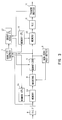
- Fig. 2 shows a multi-step quantization refinement circuit included in the encoder circuit 20.
- the multi-step quantization refinement circuit is structured by a discrete cosine transform (DCT) circuit 4 and quantization circuits, etc..
- DCT discrete cosine transform
- the DCT circuit 4 transforms the inputted data into a DCT coefficient and supplies it to the quantization circuit.
- the quantization circuit inputs DCT coefficient into a quantizer 5q out of quantizers 5q to 5q-n of a number of n+1, which quantizer 5q having the largest quantization scale, in order to quantize the DCT coefficient by a quantization scale q.
- the quantized DCT coefficient is given to a non-zero position identification circuit 6.
- the quantization scale q at this time is set as follows.
- An VLC circuit 10 performs runlength coding to convert the inputted quantized DCT coefficient into the data represented by a pair of the length of zero value and the successive non-zero value, and performs variable length coding on the data by using the predetermined conversion table to produce the coded data for transmission, and outputs it to a transmission buffer 11.
- the transmission buffer 11 stores the coded data for transmission once, and outputs it at the predetermined timing. Therefore, the data which has already quantized, runlength coded, and variable-length coded, which corresponds to the block before the DCT coefficient to be quantized from now, is stored once in the transmission buffer 11.
- the quantization scale controller 12 monitors the stored amount of the data stored in the buffer 11, controls the quantization scale q of the quantizer 5q for the DCT coefficient to be quantized from now in order that the transmission buffer 11 does not overflow or underflow, and simultaneously, controls the quantization scale of each quantizer in response to the quantization scale q.
- the rate control mechanism described above is realized by such quantization scale control.
- the non-zero position identification circuit 6 identifies the position of the quantized coefficient having a value other than zero value among the quantized DCT coefficients, and supplies the position information to masking circuits 9q-1, 9q-2, ... 9q-n of a number-n. Based on the position information supplied from the non-zero position identification circuit, these number-n masking circuits 9q-1, 9q-2, ... 9q-n supplies, to respective quantizers 5q-1, 5q-2, ...
- changing the input value to zero is referred to as masking.
- the quantizers 5q-1, 5q-2, ... 5q-n of a number-n quantize again the input DCT coefficients by using the quantization scales q-1, q-2, ... q-n respectively.
- the DCT coefficients having zero value is zero in the quantized DCT coefficients after quantization, so that only the set ⁇ Z ⁇ of non-zero value is actually quantized again by the requantization, and the accuracy is improved.
- the quantized DCT coefficients respectively quantized by the quantizers 5q-1, 5q-2, ... 5q-n are inputted into these corresponding inspection circuits 7q, 7q-1, 7q-2, ... 7q-n.
- the inspection circuits 7q, 7q-1, 7q-2, ... 7q-n inspect the quality of a refined quantized coefficient.
- the inspection includes monitoring of an increase of bit number necessary to the quantization refinement scheme and inspecting of the quality of the refined quantized DCT coefficient.
- each inspection circuit has the same construction inside as the VLC 10, and performs tentative runlength coding and variable length coding on each quantized DCT coefficient to supply the information having the obtained code length to the selection circuit 8.
- the selection circuit 8 selects the quantized DCT coefficient corresponding to the quality requested and the quantization scale corresponding to the quantized DCT coefficient. Further, comparing the code length obtained from the quality inspection circuit 7q and the code length obtained from other each of inspection circuits, if the code length increase corresponding to the quantized DCT coefficient selected based on the requested quality exceeds the maximum permitted code length increase, the quantized DCT coefficient and its quantization scale is outputted, the quantized DCT coefficient corresponding to the quality close to the requested quality within the limit of the maximum permitted code length increase.
- the quantized DCT coefficient corresponding to the minimum quantization scale within the limit of the maximum permitted code length increase can be selected.
- the quantized DCT coefficient is selected in this embodiment on the basis of the quality not to become the surplus quality.
- the VLC circuit performs runlength coding and variable length coding on the quantized DCT coefficient output from the selection circuit 8, and outputs the obtained coded code to the transmission buffer 11. Further, the VLC circuit also codes the quantization scale corresponding to the selected quantized DCT coefficient as a coded code.
- the transmission buffer 11 stores the coded code once and outputs the coded code at the predetermined timing.
- the masking circuits are provided at the previous stage of the quantizers.
- the masking circuits can be provided behind the quantizers, and can mask the quantized DCT coefficients corresponding to the position where the quantized DCT coefficient changed to zero value by the quantizer 5q.
- the masking circuits are provided for respective quantizers.
- the DCT coefficient can be assigned to each quantizer.
- the quality is inspected by comparing the practical DCT coefficient ad each quantized DCT coefficient.
- the quantized DCT coefficient by one quantization scale are compared with the quantized DCT coefficient by the quantization scale which is one stage smaller, and the quantized DCT coefficient at the time when the difference in the quality improvement was gone can be selected.
- the scale of circuit becomes larger than a multi-step quantization refinement circuit 2 which will be described below, but processing speed is improved by the parallel processing of quantization.
- a set ⁇ A ⁇ of DCT coefficients from a DCT circuit 4 is stored in a memory 13.
- a memory controller 14 controls writing and reading of the memory 13.
- the DCT coefficients read from the memory 13 are supplied to a masking circuit 9.
- the masking circuit 9 outputs the supplied DCT coefficients untouched when a quantizer 5 quantizes using the initial quantization scale q, and outputs zero when the quantizer 5 quantizes again after changing the other DCT coefficients other than a set ⁇ Z ⁇ of non-zero value detected by a non-zero position detecting circuit 6 into zero.
- the quantization circuit 5 quantizes the DCT coefficients based on the quantization scale set by a quantization scale controller 17.
- the quantized DCT coefficients output from the quantizer 5 is superscribed and stored in a memory 15 successively, while the DCT coefficient in the same block is quantized repeatedly.
- a memory controller 16 controls writing and reading of the memory 15.
- the quantized DCT coefficients read from the memory 15 is output via the VLC 10 and the transmission buffer 11.
- the inspection circuit 7 monitors the quality inspection of the quantized DCT coefficients and the code length increase due to quantization refinement, similar to the inspection circuits 7q, 7q-1, 7q-2, ... 7q-n in Fig. 2, and at the same time, requests the change of the quantization scale to the quantization scale controller 17 if necessary. Moreover, the inspection circuit 7 sends to the memory controller 14 the signal for requesting rereading of DCT coefficients from the memory 13, and requests reading of refined quantized DCT coefficients from the memory 15 to the memory controller 16.
- the quantization scale controller 17 composed of the above rate control mechanism cooperating with the transmission buffer 11 similar to the quantization scale controller 12 in Fig. 2, and sets the initial quantization scale q. Further, the quantization scale controller 17 sets successively a plurality of different quantization scales in response to the request of changing the quantization scale from the inspection circuit 7.
- Fig. 4 shows the multi-step quantization refinement procedure in an encoder circuit 20 using the multi-step quantization refinement circuit (No.2).
- the process in the portion surrounded by a broken line in the figure is the specific process in the multi-step quantization refinement scheme.
- step SP1 when the quantization process starts (step SP1), the initial quantization scale q is produced by the rate control mechanism (step SP2), and the DCT coefficient read from the memory 13 is supplied to the quantizer 5.
- the quantizer 5 successively quantizes the DCT coefficient by using the initial quantization scale q (step SP3).
- step SP4 When a quantization refinement process is not selected or the conventional quantization process is employed, it directly proceeds to step SP4, and the quantized DCT coefficient and the produced quantization scale are coded at the VLC circuit 10 as the coded data for transmission.
- the non-zero position identification circuit 6 identifies the positions of the sets of non-zero quantized DCT coefficient and memorizes the positions, and a refinement process of the quantized DCT coefficients placed at these positions starts (step SP5).
- step SP6 the same DCT coefficient as the DCT coefficient quantized at step SP3 is reread from the memory 13, and the masking circuit 9 performs masking on the DCT coefficient at zero position by using the position information stored in the non-zero position identification circuit 6.
- the quantizer 5 requantizes the DCT coefficient at the position identified as non-zero value by using the quantization scale q-1 which is one stage lower.
- the quality of the quantized DCT coefficient refined by the quantizer 5 and the increase of the code length are inspected by the inspection circuit 7, so as to judge whether or not the improvement is needed.
- step SP7 If an affirmative result is obtained in step SP7 (or in case that quality improvement of the refined quantized DCT coefficient is necessary), it proceeds to step SP8 to increase a value of parameter x and returns to the step SP5. Consequently, the value of parameter x increases from "1" to "2".
- the DCT coefficient at a position of the quantized DCT coefficient of non-zero is quantized by a quantization scale q-2 of low by one step in order to inspect the quality of quantized DCT coefficient.
- quantization by the quantization scales q-3, q-4, ... q-n of small by one step are repeated.
- steps SP5 to SP8 are repeated until a negative result is obtained in the step SP7 or a necessity to improve the quality of the refined quantized DCT coefficient disappears.
- the quality inspection circuit 7 sends to the memory controller 16 the instruction to read the refined DCT coefficient from the memory 15, the latest quantized DCT coefficient is read from the memory 15, and a series of the multi-step quantization refinement process terminates.
- the inspection at step SP7 includes monitoring of the increase of the bit number necessary to refinement of quantization and inspecting of the quality of the refined quantized DCT coefficient as described above. Further, the foundation of the inspection of the refined quantized DCT coefficient are gains of signal-to-noise ratio between the practical DCT coefficient and the refined quantized DCT coefficient, mean square error between the practical DCT coefficient and the refined quantized DCT coefficient, or the deviation of the refined quantized DCT coefficient for the practical DCT coefficient.
- the masking circuit is provided in the previous stage of the quantizer.
- the masking circuit can be provided behind the quantizer, and in quantization using the initial quantization scale q, the quantized DCT coefficient corresponding to the position of zero can be changed into zero value.
- the practical DCT coefficient is compared with each quantized DCT coefficient to inspect the quality.
- the quantized DCT coefficient by one quantization scale can be compared with the quantized DCT coefficient by the quantization scale one stage lower successively, to select the quantized DCT coefficient at the time when there is no difference in the improvement of quality.
- the processing time becomes longer than the multi-step quantization refinement circuit (No.1) described above because of necessity of the repeating action, but the circuit scale can be minimized.
- a position at which the DCT coefficient is zero is masked, and only the DCT coefficient at a position of non-zero DCT coefficient is requantized by means of these smaller quantization scales q-1, q-2, ... q-n. Consequently, the length of series of zero coefficients is not effected if it is quantized by the smaller quantization scale.
- the masking of the quantized coefficient at a zero position is important. Otherwise, there is a possibility that some leading zero coefficient becomes non-zero one due to reduction of the quantization scale. That is, it is possible to improve a precision of the non-zero coefficient without effect of the length of series of zero coefficients.
- Fig. 5 shows a single-step quantization refinement circuit included in the encoder circuit 20.
- the single-step quantization refinement circuit is structured by a discrete cosine transform (DCT) circuit 4 and a quantization circuit, etc..
- DCT discrete cosine transform
- the single-step quantization refinement circuit uses two quantization scales of an initial quantization scale q for omitting repeating operation of DCT coefficient refinement process and one quantization scale q-c having a small step quantization scale.
- a data set ⁇ A ⁇ transformed into the DCT coefficient is given to a quantizer 31q and it is quantized with the initial quantization scale q given from a quantization scale controller 34.
- the initial quantization scale q is set by the rate control mechanism similar to the case of the multi-step quantization refinement.
- a position in which a coefficient value is non-zero among the quantized DCT coefficients is identified by a non-zero position identification circuit 32 and it is given to a masking circuit 33.
- a quantizer 31q-c ( ⁇ A ⁇ ⁇ ⁇ Z ⁇ ) is quantized with the practically smaller quantization scale q-c, and is outputted.
- the symbol “c” is a constant giving a fixed decrement larger than "0" and smaller than "q”.
- "c” is set to "c1" in intra mode, and is set to "c2" in inter mode, respectively.
- step SP10 when the quantization process starts (step SP10), an initial quantization scale q is produced from the rate control mechanism (step SP11), and the initial quantization scale q is supplied to the quantizer 31q.
- the quantizer 31q uses the initial quantization scale q and sequentially quantizes DCT coefficients (step SP12).
- the process proceeds from the step SP12 to the step SP13, and the quantized DCT coefficient and the produced quantization scale are coded as the coded data for transmission at the VLC circuit 10.
- a coding mode is judged whether it is inter mode or intra mode, and a quantization scale controller 34 sets the fixed decrement value "c" of the quantization scale of the quantizer 31q-c to one suitable value to respective modes.
- intra coding mode is applied to a block coded by using only DCT and quantization
- inter coding mode is applied to a block coded by using both the motion compression and DCT and quantization.
- I-picture In MPEG1 and MPEG2 described above, the coding using I-picture, P-picture, and B-picture is well known. All macro block in I-picture is intra-coded. P-picture includes both of the macro block generally intra coded, and the macro block forward predicted. B-picture includes the macro block generally intra coded, the macro block forward predicted, the macro block backward predicted, and the macro block bidirectional predicted.
- the intra mode corresponds to the macro block intra coded in I-picture, P-picture, and B-picture, and the inter mode corresponds to the other macro block.
- a quantization scale q-c2 is selected at the step SP16, then the non-zero quantized DCT coefficient is more refined by the quantization scale q-c2 (step SP18).
- a quantization scale q-c1 is selected in the step SP17, then the non-zero quantized DCT coefficient is further refined by the quantization scale q-c1 (step SP18).
- the masking circuit is provided behind the quantizer.
- the masking circuit can be provided at the previous stage of the quantizer, and the quantized DCT coefficient corresponding to the position of zero can be changed into zero when the initial quantization scale q is used to quantize.
- difficulty of the image data is compressed by linear mapping, then it is discrete-cosine-transformed. Furthermore, in a quantization of the coefficient data by the initial quantization scale q, DCT coefficient having a quantization coefficient of non-zero value is quantized again by a fixed quantization scale q-c smaller than an initial quantization scale q, so that it is possible to realize a coding in high quantization precision and good picture quality. As a result, it is possible to more reduce mosquito noise and block noise comparing to that of the conventional one.
- a scale value of the fixed quantization scale q-c is set according to a coding mode, so it is possible to realize a coding suitable to respective modes.
- linear mapping is used to reduce a dynamic range of pixel level of an image sequence.
- the present invention is not only limited to this, but may use non-linear mapping so as to reduce the dynamic range and may use a reverse mapping so as to restore the dynamic range attaining a more high ratio of compression.
- DCT coefficients of the image data transformed by a discrete cosine transform are quantized and refined.
- DCT discrete cosine transform
- dynamic ranges are compressed for each pixel and orthogonal transformed, and when the coefficient data obtained by the orthogonal transform is quantized by means of the first quantization scale, the coefficient data having the first quantization data value of non-zero is quantized by the second quantization scale smaller than the first quantization scale, so that the image signal encoding method and apparatus thereof enabling to improve the picture quality with a bit rate of the level similar to that of the conventional method and apparatus.
- An image signal encoding method and apparatus can be utilized for a disc manufacturing apparatus for manufacturing a disc in which a bit stream of MPEG1 or MPEG2 is recorded, or a transmitting apparatus of CATV transmitting a bit stream of MPEG1 or MPEG2 or a digital satellite broadcasting.
- an image signal decoding method and apparatus can be utilized for a disc reproducing apparatus for reproducing a disc in which a bit stream of MPEG1 or MPEG2 is recorded, or a receiving apparatus of CATV transmitting a bit stream of MPEG1 or MPEG2 or a digital satellite broadcasting.
- a picture recording medium according to this invention can be utilized as a recording medium in which a bit stream of MPEG1 or MPEG2 is recorded.
Landscapes
- Engineering & Computer Science (AREA)
- Multimedia (AREA)
- Signal Processing (AREA)
- Compression Or Coding Systems Of Tv Signals (AREA)
- Compression, Expansion, Code Conversion, And Decoders (AREA)
Applications Claiming Priority (3)
| Application Number | Priority Date | Filing Date | Title |
|---|---|---|---|
| JP4040494 | 1994-02-15 | ||
| JP40404/94 | 1994-02-15 | ||
| PCT/JP1995/000202 WO1995022228A1 (fr) | 1994-02-15 | 1995-02-14 | Technique et dispostif de codage de signaux d'images |
Publications (2)
| Publication Number | Publication Date |
|---|---|
| EP0699003A1 true EP0699003A1 (de) | 1996-02-28 |
| EP0699003A4 EP0699003A4 (de) | 1999-10-06 |
Family
ID=12579733
Family Applications (1)
| Application Number | Title | Priority Date | Filing Date |
|---|---|---|---|
| EP95908375A Withdrawn EP0699003A4 (de) | 1994-02-15 | 1995-02-14 | Verfahren und vorrichtung zur bildsignalkodierung |
Country Status (4)
| Country | Link |
|---|---|
| EP (1) | EP0699003A4 (de) |
| KR (1) | KR960702247A (de) |
| CN (1) | CN1123593A (de) |
| WO (1) | WO1995022228A1 (de) |
Cited By (7)
| Publication number | Priority date | Publication date | Assignee | Title |
|---|---|---|---|---|
| EP0783230A3 (de) * | 1995-11-29 | 1999-10-20 | Samsung Electronics Co., Ltd. | Transformationskodierung beliebig geformter Bildsegmente |
| WO2001033862A1 (en) * | 1999-10-29 | 2001-05-10 | Sensormatic Electronics Corporation | Method of and system for dynamic range compression and expansion |
| WO2003010972A1 (en) * | 2001-07-26 | 2003-02-06 | Koninklijke Philips Electronics N.V. | Generating a scalable coded video signal fr om a non-scalable coded video signal |
| EP1359766A2 (de) * | 1997-02-14 | 2003-11-05 | AT&T Corp. | Verfahren zur Erzeugung eines dequantizierten DC-Luminanz oder DC-Chrominanz Koeffizienten |
| EP1045590A3 (de) * | 1999-04-13 | 2005-03-09 | Matsushita Electric Industrial Co., Ltd. | Transkodierer und Transkodierungsverfahren mit Bitratenregulierung |
| US8279940B2 (en) | 1997-02-14 | 2012-10-02 | At&T Intellectual Property Ii, L.P. | System, method and computer-readable medium for encoding a signal into macroblocks |
| WO2019220433A1 (en) * | 2018-05-17 | 2019-11-21 | Amimon Ltd. | Joint source channel coding with h.265 video compression |
Families Citing this family (1)
| Publication number | Priority date | Publication date | Assignee | Title |
|---|---|---|---|---|
| GB0110748D0 (en) * | 2001-05-02 | 2001-06-27 | Apical Ltd | Image enhancement methods and apparatus therefor |
Family Cites Families (6)
| Publication number | Priority date | Publication date | Assignee | Title |
|---|---|---|---|---|
| JPS61147692A (ja) * | 1984-12-21 | 1986-07-05 | Nec Corp | デ−タ圧縮伸張方式 |
| JP2668900B2 (ja) * | 1987-11-24 | 1997-10-27 | ソニー株式会社 | 高能率符号化装置 |
| US5166987A (en) * | 1990-04-04 | 1992-11-24 | Sony Corporation | Encoding apparatus with two stages of data compression |
| US5150208A (en) * | 1990-10-19 | 1992-09-22 | Matsushita Electric Industrial Co., Ltd. | Encoding apparatus |
| JP2834305B2 (ja) * | 1990-10-19 | 1998-12-09 | 松下電器産業株式会社 | 符号化装置 |
| JP3227674B2 (ja) * | 1991-06-27 | 2001-11-12 | ソニー株式会社 | 動画像符号化装置および方法 |
-
1995
- 1995-02-14 EP EP95908375A patent/EP0699003A4/de not_active Withdrawn
- 1995-02-14 KR KR1019950704558A patent/KR960702247A/ko not_active Withdrawn
- 1995-02-14 WO PCT/JP1995/000202 patent/WO1995022228A1/ja not_active Ceased
- 1995-09-21 CN CN95190090A patent/CN1123593A/zh active Pending
Cited By (11)
| Publication number | Priority date | Publication date | Assignee | Title |
|---|---|---|---|---|
| EP0783230A3 (de) * | 1995-11-29 | 1999-10-20 | Samsung Electronics Co., Ltd. | Transformationskodierung beliebig geformter Bildsegmente |
| EP1359766A2 (de) * | 1997-02-14 | 2003-11-05 | AT&T Corp. | Verfahren zur Erzeugung eines dequantizierten DC-Luminanz oder DC-Chrominanz Koeffizienten |
| US8279940B2 (en) | 1997-02-14 | 2012-10-02 | At&T Intellectual Property Ii, L.P. | System, method and computer-readable medium for encoding a signal into macroblocks |
| US8665965B2 (en) | 1997-02-14 | 2014-03-04 | At&T Intellectual Property Ii, L.P. | System, method and computer-readable medium for encoding a signal into macroblocks |
| US9392271B2 (en) | 1997-02-14 | 2016-07-12 | At&T Intellectual Property Ii, L.P. | System, method and computer-readable medium for encoding a signal into macroblocks |
| US10027962B2 (en) | 1997-02-14 | 2018-07-17 | At&T Intellectual Property Ii, L.P. | System, method and computer-readable medium for encoding a signal into macroblocks |
| EP1045590A3 (de) * | 1999-04-13 | 2005-03-09 | Matsushita Electric Industrial Co., Ltd. | Transkodierer und Transkodierungsverfahren mit Bitratenregulierung |
| WO2001033862A1 (en) * | 1999-10-29 | 2001-05-10 | Sensormatic Electronics Corporation | Method of and system for dynamic range compression and expansion |
| WO2003010972A1 (en) * | 2001-07-26 | 2003-02-06 | Koninklijke Philips Electronics N.V. | Generating a scalable coded video signal fr om a non-scalable coded video signal |
| KR100927389B1 (ko) * | 2001-07-26 | 2009-11-19 | 아이피지 일렉트로닉스 503 리미티드 | 스케일가능하지 않은 코딩된 비디오 신호로부터 스케일가능한 코딩된 비디오 신호를 생성하는 방법 |
| WO2019220433A1 (en) * | 2018-05-17 | 2019-11-21 | Amimon Ltd. | Joint source channel coding with h.265 video compression |
Also Published As
| Publication number | Publication date |
|---|---|
| WO1995022228A1 (fr) | 1995-08-17 |
| EP0699003A4 (de) | 1999-10-06 |
| CN1123593A (zh) | 1996-05-29 |
| KR960702247A (ko) | 1996-03-28 |
Similar Documents
| Publication | Publication Date | Title |
|---|---|---|
| US5654706A (en) | System for variable length decoding digital transmission data which has been compressed by selecting a scanning pattern | |
| EP0987899B1 (de) | Adaptives variables Längenkodierungsverfahren für Videodaten | |
| US5416604A (en) | Image compression method for bit-fixation and the apparatus therefor | |
| EP0519962B1 (de) | Digitale bildkodierung mit einer zufallsabtastung der bilder | |
| KR100253931B1 (ko) | 디지탈 영상 시퀀스의 디코딩 방법 및 장치 | |
| KR100781629B1 (ko) | Dct 베이스 기술을 사용하여 압축된 정보를 기억함에 의해 압축 해제에 필요한 메모리를 감축하는 방법 및 이 방법을 구현하기 위한 디코더 | |
| US5714950A (en) | System for variable-length-coding and variable-length-decoding digitaldata | |
| JPH03204290A (ja) | 映像信号符号化方法及びその装置 | |
| US6330369B1 (en) | Method and apparatus for limiting data rate and image quality loss in lossy compression of sequences of digital images | |
| US5515105A (en) | Video signal coder using variance controlled quantization | |
| EP0699003A1 (de) | Verfahren und vorrichtung zur bildsignalkodierung | |
| WO2000018129A1 (en) | Video signal encoding method, video signal encoder, and program recorded medium | |
| KR100242635B1 (ko) | 가변장 부호화 및 가변장 복호화 시스템 | |
| US5654704A (en) | Video variable length code encoder with EOB insertion responsive to word length | |
| US5737021A (en) | Transform coefficient selection method and apparatus for a transform coding system | |
| JP2004501531A (ja) | ビデオ・データをランレングス符号化するための方法と装置 | |
| JPH04255190A (ja) | 画像データ圧縮装置 | |
| JPWO1995022228A1 (ja) | 画像信号符号化方法及び装置 | |
| KR100744442B1 (ko) | 디지털 비디오 및 이미지들에 대한 개선된 캐스케이드 압축 방법 및 시스템 | |
| JPH0730889A (ja) | 画像データ符号化装置 | |
| JPH04233373A (ja) | 画像処理方法 | |
| JPH09107545A (ja) | データストリームを復号化するときエラーをマスキングする方法と装置 | |
| KR19980030781A (ko) | 디지털 브이씨알의 양자화간격 레벨 시프트 방법 | |
| HK1033509B (en) | Methods for coding and decoding an object within an image based on segment data | |
| HK1008711B (en) | Coding and decoding of digital data |
Legal Events
| Date | Code | Title | Description |
|---|---|---|---|
| PUAI | Public reference made under article 153(3) epc to a published international application that has entered the european phase |
Free format text: ORIGINAL CODE: 0009012 |
|
| 17P | Request for examination filed |
Effective date: 19951010 |
|
| AK | Designated contracting states |
Kind code of ref document: A1 Designated state(s): DE FR GB |
|
| A4 | Supplementary search report drawn up and despatched |
Effective date: 19990823 |
|
| AK | Designated contracting states |
Kind code of ref document: A4 Designated state(s): DE FR GB |
|
| RIC1 | Information provided on ipc code assigned before grant |
Free format text: 6H 04N 7/30 A, 6H 04N 7/50 B, 6H 04N 7/26 B, 6H 04N 7/32 B |
|
| 17Q | First examination report despatched |
Effective date: 20000920 |
|
| STAA | Information on the status of an ep patent application or granted ep patent |
Free format text: STATUS: THE APPLICATION IS DEEMED TO BE WITHDRAWN |
|
| 18D | Application deemed to be withdrawn |
Effective date: 20010131 |