EP0699019B1 - Hebelmechanismus - Google Patents
Hebelmechanismus Download PDFInfo
- Publication number
- EP0699019B1 EP0699019B1 EP95305881A EP95305881A EP0699019B1 EP 0699019 B1 EP0699019 B1 EP 0699019B1 EP 95305881 A EP95305881 A EP 95305881A EP 95305881 A EP95305881 A EP 95305881A EP 0699019 B1 EP0699019 B1 EP 0699019B1
- Authority
- EP
- European Patent Office
- Prior art keywords
- lever
- support block
- spring
- panel
- housing
- Prior art date
- Legal status (The legal status is an assumption and is not a legal conclusion. Google has not performed a legal analysis and makes no representation as to the accuracy of the status listed.)
- Expired - Lifetime
Links
Images

Classifications
-
- H—ELECTRICITY
- H05—ELECTRIC TECHNIQUES NOT OTHERWISE PROVIDED FOR
- H05K—PRINTED CIRCUITS; CASINGS OR CONSTRUCTIONAL DETAILS OF ELECTRIC APPARATUS; MANUFACTURE OF ASSEMBLAGES OF ELECTRICAL COMPONENTS
- H05K7/00—Constructional details common to different types of electric apparatus
- H05K7/14—Mounting supporting structure in casing or on frame or rack
- H05K7/1401—Mounting supporting structure in casing or on frame or rack comprising clamping or extracting means
- H05K7/1402—Mounting supporting structure in casing or on frame or rack comprising clamping or extracting means for securing or extracting printed circuit boards
- H05K7/1409—Mounting supporting structure in casing or on frame or rack comprising clamping or extracting means for securing or extracting printed circuit boards by lever-type mechanisms
Definitions
- This invention relates to lever mechanisms and, more specifically a lever mechanism for clamping printed electronic circuit board panels into multi-pin sockets.
- Circuit board panels are commonly used by manufacturers, but do not retain the panels firmly in position, and can be jolted open, allowing the boards to work loose.
- DE-U-7724549 discloses a lever-type latch for a circuit board that, on closing, urges a panel into contact with a connector, but is only latched in position by being retained on a pin attached to the panel.
- DE-A-3732892 discloses a latching mechanism that is secured with a screw-type mechanism.
- GB-A-22310726 discloses a circuit board panel latching mechanism with a retaining hook.
- the object of the present invention is to provide a lever mechanism for clamping and retaining a circuit board panel in its housing.
- EP-A-0 587 451 discloses a lever mechanism for clamping a panel to a housing, the mechanism comprising a support block which, in use, is attached to a board or panel; a first lever, pivotally connected to the support block, and arranged so that, in use, it can engage with the housing when in a first position and disengages from the housing when in a second position; a second lever, pivotally mounted on the first lever, and arranged to hold the first lever in its first position by engagement with the support block; and a spring, for biasing the first lever towards the second position and also for biasing the second lever toward the position in which it engages with the support block.
- a lever mechanism for clamping a panel to a housing comprising:
- the pivotal connection of the first lever to the support block comprises a pivot pin on the lever and an elongate slot or slots in which the pivot pin is free both to rotate and move longitudinally along the slot or slots.
- the further spring can then be a coil spring bearing directly or indirectly on the pivot pin.
- the further spring bears indirectly on the pivot pin through a bearing washer.
- the pivot pin may be provided with a cam surface against which the spring acts, the cam surface being disposed and arranged to bias the first lever towards the second position.
- a first spring then preferably acts solely between the first and second levers to bias the second lever towards the position in which it engages with the support block.
- the support block may arranged to hold a stud fastener that provides an additional latch for the panel to the housing or frame in cases where the added security of tool operation is required.
- the first spring may also be arranged to include a sprag or clip which is used to retain the support block on the panel, and may be made of electrically conductive material and shaped so that it provides an electrical connection between the board and the housing.
- the first lever comprises two interconnecting longitudinal halves, each half having lugs and/or recesses on their inner surfaces to provide pivotable mountings in the form of a pivot pin for mounting the first lever on the support block, and for the second lever on the first lever.
- the lever mechanism of the present invention provides a clamping device that is easily engaged and disengaged, and that is also easily manufactured from a minimum number of components and which enables a predetermined clamp load to be provided regardless of tolerances in components of the panel and housing.
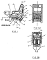
- a first lever assembly 1 is shown attached, via a support block 2, to a panel 3 which carries a printed circuit board 3'.
- the support block 2 is held on the panel 3 by a spring 8 as described below, but could be additionally secured to the panel 3 by screws, a snap-fit assembly, or the like if desired.
- Pivotally mounted in elongate slots 2' on the support block 2 is a first lever 4.
- the lever 4 comprises two sections (see Figs. 5A & 5B) which fit around the support block 2 and a second lever 9 and which also provide a pivot pin 14 against which is engaged a further, coil, spring 15 which biases the first lever away from the panel and provides a clamping force between the panel and housing in use, via the lever 4.
- the lever 4 has, on one edge, a lug 5 which, when in a locked position, engages with a lip 6 protruding from the inner edge of a housing 7 to clamp the panel in position as shown. On the same edge an opposing lug 5' is formed which engages with the opposite side of the lip 6 during unlatching, to ensure removal of the panel from the housing.
- the spring 8 Connected to the support block 2 is the spring 8 which sits within the lever 4 and urges it into an unclamped position (shown in figure 3), in which the lug 5 is disengaged from the lip 6.
- the spring 8 has a clip 8' which engages the surface of the panel 3 to resist removal of the block 2 from the panel 3.
- the second lever 9 is pivotally mounted in recesses 12 on the first lever 4.
- One end of the lever 9 is formed into a flat surface 9' so that it can be easily depressed.
- the opposite end of the lever 9 pivots.
- This end of the second lever 9 is shaped to provide a hook 10 so as to be engageable with a lip 11 positioned on the support block 2 as shown in figure 1.
- the spring 8 exerts a force on the second lever 9, which pivots to engage the hook 10 with the lip 11 thus holding the whole mechanism in a clamping position due to the pivotal mounting of the second lever 9 on the first lever 4.
- the second lever 9 is depressed, this causes it to rotate and the hook 10 of second lever 9 disengages from the lip 11 (as shown in figure 2) so that the spring 8 then urges the lever 4 into the unclamped position.
- the lever 9 is depressed, disengaging the lever 9 from the lip 11, and allowing the force of the spring 8 to move the lever 4 outward to the unclamped position.
- the engagement of the lug 5' against the opposite side of the lip 6 ensures detachment so that the panel can then be removed.
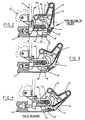
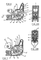
- the second example shown in figures 6 to 10 is substantially similar and the same reference numerals have been used therefore.
- the significant differences are (a) that the spring 8 is an integral part of the second lever 9 and bears only against the underside of the first lever 4, (b) that a separate spring clip 8' is used to secure the support 2 to the panel 3, and (c) that a cam surface 16 is formed on one side of the pivot pin 14 so as to be engaged by the spring 15.
- the functions of the springs 8 & 15 and the spring clip 8' are separated and the spring 15 additionally serves to bias the lever 4 to the unlatched position, the spring 8 serving only to bias the second lever 9 relative to the first lever and the clip 8' serving to retain the support 2 on the panel.
- the axis of the slots 2' is inclined to the longitudinal axis of the spring 15 and to the general direction of the support 2 and this helps to ensure engagement of the lugs 5 on the lip 6 as the lever pivots and compresses the spring.
- a lock mechanism may be provided between the second and first levers in order to lock the second lever in the latched position.
- a spring loaded locking peg may be provided on the first or second levers and may be freed to move or locked in the engaged position by a suitable key-operated lock, thus allowing the latch to be set with a key for either normal push button operation, i.e. pushing on the second lever to release the first lever, or in a mode in which the latch may be slammed shut but require operation of the lock to release it before pushing on the secondary lever allows the latch to be opened.
Landscapes
- Engineering & Computer Science (AREA)
- Microelectronics & Electronic Packaging (AREA)
- Mounting Of Printed Circuit Boards And The Like (AREA)
Claims (10)
- Hebelmechanismus (1) zum Festklemmen einer Platte (3) an einem Gehäuse, wobei der Mechanismus umfasst:dadurch gekennzeichnet, dasseinen Halteblock (2), der im Betrieb an einer Platte befestigt ist;einen ersten Hebel (4), der schwenkbar mit dem Halteblock verbunden und so angeordnet ist, dass er im Betrieb mit dem Gehäuse in Eingriff kommen kann, wenn er in einer ersten Position ist, und mit dem Gehäuse außer Eingriff kommen kann, wenn er in einer zweiten Position ist;einen zweiten Hebel (9), der schwenkbar auf dem ersten Hebel montiert undso angeordnet ist, dass er durch Eingriff mit dem Halteblock den ersten Hebel in seiner ersten Position hält; undeine Feder oder Federn (8) zum Vorspannen des ersten Hebels in die zweite Position und/oder Vorspannen des zweiten Hebels in die Position, in der er mit dem Halteblock in Eingriff ist;
der erste Hebel (4) zur Ausführung einer Translationsbewegung im Verhältnis zum Halteblock (2) gegen die Wirkung einer zweiten Feder (15) montiert ist, um im Betrieb zwischen der Platte (3) dem Gehäuse eine vorbestimmte Klemmlast vorzusehen. - Hebelmechanismus (1) nach Anspruch 1, bei dem die Schwenkverbindung des ersten Hebels (4) mit dem Halteblock (2) einen Schwenkstift (14) auf dem Hebel und einen länglichen Schlitz (2') oder Schlitze umfasst, in denen der Schwenkstift sowohl zum Drehen als auch zu einer Längsbewegung entlang des Schlitzes oder der Schlitze Freiheit hat.
- Hebelmechanismus (1) nach Anspruch 2, bei dem die weitere Feder eine Schraubenfeder ist, die direkt oder indirekt auf den Schwenkstift (14) drückt.
- Hebelmechanismus (1) nach Anspruch 2, bei dem die weitere Feder über eine Auflagescheibe indirekt auf den Schwenkstift (14) drückt.
- Hebelmechanismus (1) nach Anspruch 1 oder Anspruch 4, bei dem der Schwenkstift mit einer Nockenoberfläche versehen ist, gegen welche die Feder (8) wirkt, wobei die Nockenoberfläche so angeordnet und ausgelegt ist, dass sie den ersten Hebel (4) zur zweiten Position hin vorspannt.
- Hebelmechanismus (1) nach Anspruch 5, bei dem die Feder (8) zwischen dem ersten und zweiten Hebel so wirkt, dass sie den zweiten Hebel zu der Position hin vorspannt, in welcher er mit dem Halteblock (2) in Eingriff ist.
- Hebelmechanismus (1) nach einem der Ansprüche 1 bis 6, bei dem der Halteblock (2) so angeordnet ist, dass er ein Stiftbefestigungsmittel hält, das eine zusätzliche Verriegelung für die Platte (3) am Gehäuse oder Rahmen bietet.
- Hebelmechanismus (1) nach einem der vorhergehenden Ansprüche, bei dem die Feder (8) so angeordnet ist, dass sie einen Bolzen oder Clip aufweist, der zum Halten des Halteblocks (2) auf der Platte (3) verwendet wird.
- Hebelmechanismus (1) nach einem der vorhergehenden Ansprüche, bei dem die Feder (8) oder Federn aus elektrisch leitfähigem Material hergestellt und so geformt sind, dass sie eine elektrische Verbindung zwischen der Platte (3) und dem Gehäuse herstellen.
- Hebelmechanismus (1) nach einem der vorhergehenden Ansprüche, bei dem der erste Hebel (4) zwei miteinander verbundene Längshälften umfasst, wobei jede Hälfte auf ihrer Innenoberfläche Ansätze und/oder Vertiefungen hat, um zum Befestigen des ersten Hebels auf dem Halteblock (2) und für den zweiten Hebel (9) auf dem ersten Hebel schwenkbare Befestigungen in der Form eines Schwenkstifts (14) vorzusehen.
Applications Claiming Priority (2)
| Application Number | Priority Date | Filing Date | Title |
|---|---|---|---|
| GB9417194 | 1994-08-25 | ||
| GB9417194A GB9417194D0 (en) | 1994-08-25 | 1994-08-25 | Lever mechanism |
Publications (2)
| Publication Number | Publication Date |
|---|---|
| EP0699019A1 EP0699019A1 (de) | 1996-02-28 |
| EP0699019B1 true EP0699019B1 (de) | 2003-01-02 |
Family
ID=10760402
Family Applications (1)
| Application Number | Title | Priority Date | Filing Date |
|---|---|---|---|
| EP95305881A Expired - Lifetime EP0699019B1 (de) | 1994-08-25 | 1995-08-23 | Hebelmechanismus |
Country Status (4)
| Country | Link |
|---|---|
| US (1) | US5629836A (de) |
| EP (1) | EP0699019B1 (de) |
| DE (1) | DE69529254T2 (de) |
| GB (1) | GB9417194D0 (de) |
Cited By (1)
| Publication number | Priority date | Publication date | Assignee | Title |
|---|---|---|---|---|
| WO2014209334A1 (en) * | 2013-06-28 | 2014-12-31 | Hewlett-Packard Development Company, L.P. | Lever unit |
Families Citing this family (52)
| Publication number | Priority date | Publication date | Assignee | Title |
|---|---|---|---|---|
| US5940276A (en) * | 1995-06-12 | 1999-08-17 | Siemens Aktiengesellschaft | Front system of a printed circuit board assembly having an integrated push-button element for active-passive switching |
| US6101322A (en) * | 1996-06-05 | 2000-08-08 | Compaq Computer Corporation | Removal and insertion of expansion cards in a computer system |
| US5943482A (en) * | 1996-06-05 | 1999-08-24 | Compaq Computer Corporation | Expansion card insertion and removal |
| US5922060A (en) * | 1996-12-31 | 1999-07-13 | Compaq Computer Corporation | Expansion card insertion and removal |
| US6098132A (en) * | 1996-06-05 | 2000-08-01 | Compaq Computer Corporation | Installation and removal of components of a computer |
| US5822196A (en) * | 1996-06-05 | 1998-10-13 | Compaq Computer Corporation | Securing a card in an electronic device |
| US6073196A (en) * | 1996-06-05 | 2000-06-06 | Compaq Computer Corporation | Using communication cycles for connecting and disconnecting devices in a computer system |
| US5902144A (en) * | 1997-08-15 | 1999-05-11 | Intel Corporation | Integrated circuit package burn-in socket linkage system |
| EP0917416A1 (de) * | 1997-11-18 | 1999-05-19 | Dzus Fastener Europe Limited | Verriegelungsvorrichtung |
| GB2334151B (en) * | 1998-02-05 | 2002-06-19 | Vero Electronics Ltd | Injector/ejector device |
| DE19807555C1 (de) * | 1998-02-23 | 1999-12-02 | Siemens Ag | Aufbausystem zum Einschub von elektrischen Flachbaugruppen |
| FR2779901B1 (fr) | 1998-06-12 | 2000-09-01 | Sextant Avionique | Dispositif d'insertion, d'extraction et de verrouillage d'un module dans une baie |
| US5978233A (en) * | 1998-06-18 | 1999-11-02 | Roscoe; Brett D. | Swell-latch printed circuit board latching and ejecting mechanism |
| US6515866B2 (en) | 1998-12-23 | 2003-02-04 | Elma Electronic Ag | Plug module with active-passive switching |
| IL173325A (en) | 1998-12-28 | 2009-11-18 | Elma Electronic Ag | Lever for insertion and removal of plug module |
| EP1453365B1 (de) * | 1998-12-28 | 2006-06-28 | Elma Electronic Ag | Steckbaugruppe mit Aktiv-Passiv-Schaltung und Ein- und Aushebegriff für eine derartige Steckbaugruppe |
| DE29922725U1 (de) * | 1999-12-23 | 2001-03-01 | Siemens AG, 80333 München | Betätigungselement zum Ein- und Aushebeln von Flachbaugruppen mit Verriegelungsschieber, Frontelement für eine Flachbaugruppe mit Betätigungselement und Baugruppenträger zur Aufnahme von Flachbaugruppen |
| US6366457B1 (en) * | 2000-08-30 | 2002-04-02 | International Business Machines Corporation | Bracket for mounting a computer drive device |
| GB2370920B (en) | 2001-01-09 | 2003-01-15 | Sun Microsystems Inc | Ejector mechanism |
| JP3493628B2 (ja) * | 2001-01-18 | 2004-02-03 | 日本航空電子工業株式会社 | コネクタ装置 |
| US7245632B2 (en) * | 2001-08-10 | 2007-07-17 | Sun Microsystems, Inc. | External storage for modular computer systems |
| GB2381953B (en) * | 2001-11-08 | 2004-04-28 | Sun Microsystems Inc | Rack-mountable systems |
| US20030145705A1 (en) * | 2002-02-04 | 2003-08-07 | Blaine Miller | Fence |
| US20030156399A1 (en) * | 2002-02-15 | 2003-08-21 | Cerniglia Sean A. | Integrated bulkhead handle assembly |
| WO2003092346A1 (en) * | 2002-04-26 | 2003-11-06 | Telefonaktiebolaget Lm Ericsson | Board injector/extractor |
| US20040040117A1 (en) * | 2002-09-04 | 2004-03-04 | Purcell Brackets, Inc. | Ejector handle |
| JP2004234194A (ja) * | 2003-01-29 | 2004-08-19 | Toshiba Corp | 電子機器 |
| US6884096B2 (en) * | 2003-04-29 | 2005-04-26 | International Business Machines Corporation | Apparatus for positioning an electrical assembly within a housing |
| US6791843B1 (en) | 2003-06-11 | 2004-09-14 | Hewlett-Packard Development Company, L.P. | Parallel board connection system and method |
| US6967847B2 (en) * | 2003-06-11 | 2005-11-22 | Hewlett-Packard Development Company, L.P. | Computer system with movable card guide |
| US6956746B2 (en) * | 2003-06-20 | 2005-10-18 | Hewlett-Packard Development Company, L.P. | Electronic system with a movable printed circuit assembly |
| US7349228B1 (en) * | 2003-11-24 | 2008-03-25 | Extreme Networks | Ejector assembly for rack-mounted computing devices |
| DE502005003938D1 (de) * | 2004-03-19 | 2008-06-19 | Elma Electronic Ag | Ein- und Aushebevorrichtung für Steckbaugruppen |
| US7251145B1 (en) * | 2004-08-18 | 2007-07-31 | Sun Microsystems, Inc. | Inject/eject mechanism for circuit boards |
| KR100629958B1 (ko) | 2005-01-15 | 2006-09-28 | 황동원 | 반도체용 테스트 및 번인을 위한 비지에이형 소켓 |
| CN102016752B (zh) * | 2008-04-29 | 2013-03-27 | 惠普开发有限公司 | 用于计算机设备的弹射机构 |
| FR2944670A1 (fr) * | 2009-04-15 | 2010-10-22 | Radiall Sa | Ensemble de verrouillage de carte electronique sur un rack. |
| US8167126B2 (en) * | 2009-09-29 | 2012-05-01 | Apple Inc. | Button mechanisms for electronic device cases |
| US8292647B1 (en) * | 2011-06-13 | 2012-10-23 | Tyco Electronics Corporation | Socket connector |
| US8925179B2 (en) | 2011-08-19 | 2015-01-06 | Gables Engineering, Inc. | Mounting and fastening mechanism |
| US9988021B1 (en) | 2013-02-18 | 2018-06-05 | Otis Young | Trailer jack plunger pin release system |
| US8714528B1 (en) | 2013-02-18 | 2014-05-06 | Otis Young | Trailer jack plunger pin release lever system |
| US10110978B2 (en) | 2016-02-19 | 2018-10-23 | Facebook, Inc. | Wavelength division multiplexer with packet switching based on header information or performance metric information for optical channels |
| US10356955B2 (en) | 2016-05-11 | 2019-07-16 | Facebook, Inc. | Modular network switches, associated structures, and associated methods of manufacture and use |
| US10645027B2 (en) | 2016-09-30 | 2020-05-05 | Facebook, Inc. | Network switches configured to employ optical or electrical interfaces |
| US10374709B2 (en) | 2017-07-20 | 2019-08-06 | Facebook, Inc. | Chromatic dispersion management |
| US10873544B2 (en) | 2017-09-14 | 2020-12-22 | Facebook, Inc. | Switching using a power bar pass-through card |
| US10476816B2 (en) | 2017-09-15 | 2019-11-12 | Facebook, Inc. | Lite network switch architecture |
| US10425331B2 (en) | 2017-10-04 | 2019-09-24 | Facebook, Inc. | Pre-routing device for data centers |
| US20200321730A1 (en) * | 2019-06-21 | 2020-10-08 | Intel Corporation | Small form factor connection mechanism for a card to card connector |
| TWM599347U (zh) * | 2020-05-25 | 2020-08-01 | 伍鐌科技股份有限公司 | 扣件結構 |
| US11606874B2 (en) * | 2021-03-18 | 2023-03-14 | Dell Products L.P. | Tolerance absorbing lever mechanism |
Family Cites Families (11)
| Publication number | Priority date | Publication date | Assignee | Title |
|---|---|---|---|---|
| US2869909A (en) * | 1955-05-11 | 1959-01-20 | Mc Graw Edison Co | Latch |
| US2872234A (en) * | 1957-02-15 | 1959-02-03 | Earl M Brinton | Latch |
| DE7724549U1 (de) | 1977-08-06 | 1978-01-19 | Robert Bosch Gmbh, 7000 Stuttgart | Einschub- und Ausziehhilfe |
| US4157583A (en) | 1977-11-04 | 1979-06-05 | General Electric Company | Circuit board clamping assembly |
| DE3508580A1 (de) * | 1985-03-11 | 1986-09-11 | Siemens AG, 1000 Berlin und 8000 München | Steck- und ziehhilfe |
| DE3732892A1 (de) | 1987-09-30 | 1989-04-20 | Festo Kg | Aus einer aufnahmeeinrichtung und mindestens einem traeger von z. b. elektrischen oder pneumatischen bauteilen bestehende anordnung |
| JPH01269762A (ja) * | 1988-04-22 | 1989-10-27 | Tokai Shinku Kenkyusho:Kk | 真空チャンバの扉のクランプ機構及び真空チャンバ付き作業ボックス |
| ES2014614A6 (es) | 1989-05-10 | 1990-07-16 | Telefonica Nacional Espana Co | Caratula apantallada con mecanismo de extraccion-retencion. |
| GB9126235D0 (en) * | 1991-12-11 | 1992-02-12 | Bicc Plc | Enclosure for circuit boards |
| GB9219322D0 (en) | 1992-09-11 | 1992-10-28 | Dzus Fastener Europe | Lever mechanism |
| DE4428529C1 (de) * | 1994-08-12 | 1995-08-24 | Schroff Gmbh | Vorrichtung zum Ausziehen einer Steckbaugruppe |
-
1994
- 1994-08-25 GB GB9417194A patent/GB9417194D0/en active Pending
-
1995
- 1995-08-23 DE DE69529254T patent/DE69529254T2/de not_active Expired - Fee Related
- 1995-08-23 EP EP95305881A patent/EP0699019B1/de not_active Expired - Lifetime
- 1995-08-25 US US08/519,607 patent/US5629836A/en not_active Expired - Fee Related
Cited By (1)
| Publication number | Priority date | Publication date | Assignee | Title |
|---|---|---|---|---|
| WO2014209334A1 (en) * | 2013-06-28 | 2014-12-31 | Hewlett-Packard Development Company, L.P. | Lever unit |
Also Published As
| Publication number | Publication date |
|---|---|
| US5629836A (en) | 1997-05-13 |
| DE69529254T2 (de) | 2003-06-26 |
| GB9417194D0 (en) | 1994-10-12 |
| DE69529254D1 (de) | 2003-02-06 |
| EP0699019A1 (de) | 1996-02-28 |
Similar Documents
| Publication | Publication Date | Title |
|---|---|---|
| EP0699019B1 (de) | Hebelmechanismus | |
| EP0587451B1 (de) | Hebelsystem | |
| US6373713B1 (en) | Single handle printed circuit board assembly insertion, extraction, sensing and locking mechanism | |
| KR100310428B1 (ko) | 편평 가요성 회로용 커넥터 | |
| CN101874329B (zh) | 具有旋转致动器的柔性印刷电路连接器 | |
| US5401179A (en) | Locking mechanism for a connector assembly of low engaging/disengaging force type | |
| US4931907A (en) | Electric module latch assembly | |
| US7175451B2 (en) | Lever mated connector assembly with a position assurance device | |
| US5797772A (en) | Connector provided with a retainer | |
| US6275378B1 (en) | Safety lock for notebook-type computer dock | |
| US5634809A (en) | Connector with lock mechanism | |
| EP1373667A4 (de) | Druck-schloss | |
| US4947289A (en) | Latch mechanism for a plug-in cartridge or the like | |
| US4863395A (en) | Zero insertion force connector with component card | |
| US4787858A (en) | Latching system for computer plug | |
| US20030039100A1 (en) | Insertion latch and ejectable pull handle for rack mounted electronic devices | |
| US5364287A (en) | Connector restraining apparatus | |
| JPH07192800A (ja) | 端子位置保証機構を有する電気コネクタ | |
| JPH09180570A (ja) | スイッチボックスの取付構造 | |
| US5963422A (en) | Systems and methods for releaseably securing an article within a computer system | |
| US20230028263A1 (en) | Card retainers | |
| JPH06245348A (ja) | 電子ユニットのロック装置 | |
| JPH11512225A (ja) | 2つの半体プラグを有する、壁に固定するための組合せ | |
| US6017236A (en) | Mechanism for detecting an unlocked state of connectors | |
| US20040057219A1 (en) | Computer module with integrated cover latching and attachment mechanism |
Legal Events
| Date | Code | Title | Description |
|---|---|---|---|
| PUAI | Public reference made under article 153(3) epc to a published international application that has entered the european phase |
Free format text: ORIGINAL CODE: 0009012 |
|
| AK | Designated contracting states |
Kind code of ref document: A1 Designated state(s): CH DE GB IT LI SE |
|
| 17P | Request for examination filed |
Effective date: 19960809 |
|
| RAP1 | Party data changed (applicant data changed or rights of an application transferred) |
Owner name: MCKECHNIE SPECIALIST PRODUCTS LIMITED |
|
| GRAG | Despatch of communication of intention to grant |
Free format text: ORIGINAL CODE: EPIDOS AGRA |
|
| 17Q | First examination report despatched |
Effective date: 20020516 |
|
| GRAG | Despatch of communication of intention to grant |
Free format text: ORIGINAL CODE: EPIDOS AGRA |
|
| GRAH | Despatch of communication of intention to grant a patent |
Free format text: ORIGINAL CODE: EPIDOS IGRA |
|
| GRAH | Despatch of communication of intention to grant a patent |
Free format text: ORIGINAL CODE: EPIDOS IGRA |
|
| GRAA | (expected) grant |
Free format text: ORIGINAL CODE: 0009210 |
|
| AK | Designated contracting states |
Kind code of ref document: B1 Designated state(s): CH DE GB IT LI SE |
|
| PG25 | Lapsed in a contracting state [announced via postgrant information from national office to epo] |
Ref country code: LI Free format text: LAPSE BECAUSE OF FAILURE TO SUBMIT A TRANSLATION OF THE DESCRIPTION OR TO PAY THE FEE WITHIN THE PRESCRIBED TIME-LIMIT Effective date: 20030102 Ref country code: CH Free format text: LAPSE BECAUSE OF FAILURE TO SUBMIT A TRANSLATION OF THE DESCRIPTION OR TO PAY THE FEE WITHIN THE PRESCRIBED TIME-LIMIT Effective date: 20030102 |
|
| REG | Reference to a national code |
Ref country code: GB Ref legal event code: FG4D Free format text: 20030102 |
|
| REG | Reference to a national code |
Ref country code: CH Ref legal event code: EP |
|
| RAP2 | Party data changed (patent owner data changed or rights of a patent transferred) |
Owner name: MCKECHNIE SPECIALIST PRODUCTS LIMITED |
|
| REF | Corresponds to: |
Ref document number: 69529254 Country of ref document: DE Date of ref document: 20030206 Kind code of ref document: P |
|
| REG | Reference to a national code |
Ref country code: SE Ref legal event code: TRGR |
|
| REG | Reference to a national code |
Ref country code: CH Ref legal event code: PL |
|
| PG25 | Lapsed in a contracting state [announced via postgrant information from national office to epo] |
Ref country code: SE Free format text: LAPSE BECAUSE OF NON-PAYMENT OF DUE FEES Effective date: 20030824 |
|
| PLBE | No opposition filed within time limit |
Free format text: ORIGINAL CODE: 0009261 |
|
| STAA | Information on the status of an ep patent application or granted ep patent |
Free format text: STATUS: NO OPPOSITION FILED WITHIN TIME LIMIT |
|
| 26N | No opposition filed |
Effective date: 20031003 |
|
| EUG | Se: european patent has lapsed | ||
| PGFP | Annual fee paid to national office [announced via postgrant information from national office to epo] |
Ref country code: GB Payment date: 20040915 Year of fee payment: 10 |
|
| PGFP | Annual fee paid to national office [announced via postgrant information from national office to epo] |
Ref country code: DE Payment date: 20040916 Year of fee payment: 10 |
|
| PG25 | Lapsed in a contracting state [announced via postgrant information from national office to epo] |
Ref country code: IT Free format text: LAPSE BECAUSE OF NON-PAYMENT OF DUE FEES;WARNING: LAPSES OF ITALIAN PATENTS WITH EFFECTIVE DATE BEFORE 2007 MAY HAVE OCCURRED AT ANY TIME BEFORE 2007. THE CORRECT EFFECTIVE DATE MAY BE DIFFERENT FROM THE ONE RECORDED. Effective date: 20050823 Ref country code: GB Free format text: LAPSE BECAUSE OF NON-PAYMENT OF DUE FEES Effective date: 20050823 |
|
| PG25 | Lapsed in a contracting state [announced via postgrant information from national office to epo] |
Ref country code: DE Free format text: LAPSE BECAUSE OF NON-PAYMENT OF DUE FEES Effective date: 20060301 |
|
| GBPC | Gb: european patent ceased through non-payment of renewal fee |
Effective date: 20050823 |