EP0699404A1 - Ferrure pour incliner des éléments de mobilier - Google Patents
Ferrure pour incliner des éléments de mobilier Download PDFInfo
- Publication number
- EP0699404A1 EP0699404A1 EP95104266A EP95104266A EP0699404A1 EP 0699404 A1 EP0699404 A1 EP 0699404A1 EP 95104266 A EP95104266 A EP 95104266A EP 95104266 A EP95104266 A EP 95104266A EP 0699404 A1 EP0699404 A1 EP 0699404A1
- Authority
- EP
- European Patent Office
- Prior art keywords
- guide rail
- clamping slide
- slide
- guide
- rail
- Prior art date
- Legal status (The legal status is an assumption and is not a legal conclusion. Google has not performed a legal analysis and makes no representation as to the accuracy of the status listed.)
- Granted
Links
- 239000002184 metal Substances 0.000 claims description 3
- 238000013459 approach Methods 0.000 claims 1
- 230000013011 mating Effects 0.000 description 5
- 238000004080 punching Methods 0.000 description 4
- 210000002105 tongue Anatomy 0.000 description 4
- 238000005452 bending Methods 0.000 description 1
- 238000006073 displacement reaction Methods 0.000 description 1
- 230000002349 favourable effect Effects 0.000 description 1
- 238000003780 insertion Methods 0.000 description 1
- 230000037431 insertion Effects 0.000 description 1
- 230000035515 penetration Effects 0.000 description 1
Images
Classifications
-
- A—HUMAN NECESSITIES
- A47—FURNITURE; DOMESTIC ARTICLES OR APPLIANCES; COFFEE MILLS; SPICE MILLS; SUCTION CLEANERS IN GENERAL
- A47B—TABLES; DESKS; OFFICE FURNITURE; CABINETS; DRAWERS; GENERAL DETAILS OF FURNITURE
- A47B27/00—Drawing desks or tables; Carriers for drawing-boards
- A47B27/02—Adjustable drawing tables without balancing means
-
- A—HUMAN NECESSITIES
- A47—FURNITURE; DOMESTIC ARTICLES OR APPLIANCES; COFFEE MILLS; SPICE MILLS; SUCTION CLEANERS IN GENERAL
- A47B—TABLES; DESKS; OFFICE FURNITURE; CABINETS; DRAWERS; GENERAL DETAILS OF FURNITURE
- A47B17/00—Writing-tables
- A47B17/02—Writing-tables with vertically-adjustable parts
-
- A—HUMAN NECESSITIES
- A47—FURNITURE; DOMESTIC ARTICLES OR APPLIANCES; COFFEE MILLS; SPICE MILLS; SUCTION CLEANERS IN GENERAL
- A47B—TABLES; DESKS; OFFICE FURNITURE; CABINETS; DRAWERS; GENERAL DETAILS OF FURNITURE
- A47B2200/00—General construction of tables or desks
- A47B2200/0035—Tables or desks with features relating to adjustability or folding
- A47B2200/004—Top adjustment
- A47B2200/0043—Inclination adjustable work top
Definitions
- the invention relates to an inclined fitting for pieces of furniture with a furniture part that can be inclined about a horizontal articulation axis, in particular for desks with an inclinable writing surface, for supporting the furniture part in the respective inclined position, the fitting being attached to the piece of furniture stationary below the inclined furniture part with a course that is perpendicular to the articulation axis
- the guide rail also having an upwardly pointing guide surface and a downwardly pointing guide surface and the clamping slide forms counter surfaces interacting with the guide surfaces, such that the clamping slide sits on the guide rail with tilting swivel play and at one from the support lever to the clamping slide pressure exerted at the rear assumes a tilted swivel position tilted backwards and is tilted on the guide rail and, when the
- the guide rail is formed by a flat bar which is overlapped on both sides by a guide plate of the clamping slide, the top and bottom of the flat bar the two guide surfaces and bolts extending between the two guide plates of the clamping slide and a pressure piece resiliently mounted on the clamping slide Form counter surfaces.
- the actuating rod hangs down over two parallelogram levers from the guide rail and, in its raised position of use, pushes the clamping slide up at the rear, so that a support body which can be swiveled above the guide rail and is arranged on the clamping slide can pivot onto the upper side of the guide rail and the clamping slide holds in its sliding pivot position.
- the present invention is based on the object to provide an inclined fitting of the type mentioned, which has a compact and low-parts structure.
- the guide rail is a longitudinally slotted hollow rail on its upper side for the passage of the clamping slide and / or the support lever, which contains a longitudinal channel which is wider with respect to the longitudinal slot and in which at least the one having the counter surfaces has reference to the longitudinal slot wider area of the clamping slide is arranged such that the upward-facing guide surface of the guide rail is formed by a lower channel wall and the downward-pointing guide surface of the guide rail is formed by an upper channel wall that the lower counter surface of the clamping slide assigned to the upwardly pointing guide surface is shorter than the upper mating surface assigned to the downward-facing guide surface and in the longitudinal direction between the front and rear ends of the upper mating surface is arranged near the front end and at a greater distance from the rear end, and he actuating rod one in the longitudinal channel the guide rail below the clamping slide forms a sliding rail which faces a downward-facing sliding surface of the clamping slide, so that in the raised position of use of the actuating rod, the clamping slide rests on the slide rail in
- Such a clamping slide can be made in one piece overall. Furthermore, the clamping slide and the actuating rod are housed inside the guide rail, so that there is a compact design and the clamping slide and the actuating rod are not visible from the outside.
- a further advantage is that the clamping slide sliding backwards when the furniture part is pivoted downwards immediately reaches its tilted swivel position and thus tilted when the actuating rod is lowered into its non-use position.
- the clamping slide remains in its sliding-pivot position after the actuating arm is released due to the pivoted-in supporting body, so that the swivel-mounted furniture part can accidentally fall all the way down.
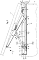
- a desk is indicated by dash-dotted lines, on the body 1 of which a writing surface 2 is attached so as to be inclinable about a horizontal articulation axis 3, which extends along the region of the front edge of the writing surface.
- the writing surface 2 can thus be swung up from its horizontal position, not shown, in the direction of arrow 4 at the rear.
- An inclined fitting 5, which is described in detail below, is used to fix the writing surface 2 by supporting it from below in the different inclined positions. It should be pointed out beforehand that this fitting is not only for desks with an adjustable writing surface, but in general for furniture can be used, which have an inclinable furniture part.
- the fitting 5 contains a guide rail 6, which is fixed beneath the writing surface 2 in a fixed position on the body 1 and extends at right angles to the articulation axis 3, preferably in the region of half the length of the writing surface 2.
- a clamping slide 7 is guided in the longitudinal direction of the rail, to which a support lever 8 is articulated at the top via an articulated axis 9, which points obliquely toward the top of the articulation axis 3 and belongs to a support rod supporting the writing plate 2.
- the end of the support lever 8 facing away from the clamping slide 7 is articulated via a pivot axis 13 approximately half the length of a holding lever 10 which, on the one hand, is pivotably attached to the guide rail 6 at a point arranged between the clamping slide 7 and the front end of the guide rail 6 about a pivot pin 11 is and on the other hand carries at its free end a rotating roller 12 which bears against the writing plate 2 from below and supports it.
- a coil spring 14 is tensioned, which supports the pivoting of the writing plate 2 in the direction of arrow 4.
- the spring force dimensioned so that the writing plate remains below its weight against the force of the spring 14 below.
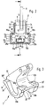
- the guide rail 6 forms an upward-facing guide surface, which in the exemplary embodiment is divided into two individual guide surfaces running at a distance from one another, and a downward-pointing guide surface which is also divided into two individual guide surfaces 17a, 17b, which run at a distance from one another.
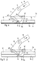
- These arranged on the guide rail 6 and extending in the longitudinal direction of the guide surfaces cooperate with the counter surfaces provided on the clamping slide 7, in such a way that the clamping slide 7 sits with tilt tilt play on the guide rail 6 and one of the support lever 8 on the clamping slide 7 backward pressure force (arrow 18) assumes a tilted swivel position tilted backwards and is tilted on the guide rail 6 (FIG. 4) and assumes a slide swivel position raised at the rear when a pulling force is exerted (arrow 19) and can slide forward along the guide rail 6 (Fig. 5).
- an actuating rod 20 is arranged on the guide rail 6, which extends along the guide rail 6 and is adjustable between a lowered non-use position (FIGS. 1, 2 and 4) and a raised position for use (FIG. 5).
- the actuating rod 20 lifts the clamping slide 7 into the sliding pivot position (FIG. 5), in which the clamping slide can then slide backwards.
- the guide rail 6 is a longitudinally slotted hollow rail on its upper side 21, which is made of sheet metal in the exemplary embodiment, but also in another Way could be manufactured hollow section.
- This hollow rail contains a longitudinal channel 23 which is wider with respect to the longitudinal slot 22 on the top and in which at least the area 24 having the counter surfaces is arranged by the clamping slide 7.
- This clamping slide region 24, like the longitudinal channel 23 receiving it, is wider than the longitudinal slot 22.
- the clamping slide 7 is inserted into the guide rail 5 by inserting it from the end of the guide rail. This insertion takes place before the end of the guide rail 6 is closed by means of end caps 25, 26.
- the longitudinal slot 22 serves for the penetration of the clamping slide 7 and / or the support lever 8, which depends on the location of the hinge axis 9.
- the hinge axis 9 is located approximately at the level of the upper edge of the guide rail, so that the clamping slide 7 emerges somewhat upwards and the support lever 8 engages somewhat in the guide rail and thereby engages in a fork-like recess of the clamping slide, where it is articulated by means of the hinge axis 9 is.
- the upward-facing guide surface 16a, 16b of the guide rail 6 is formed by a lower wall 27 of the longitudinal channel 23 and the downward-pointing guide surface 17a, 17b of the guide rail 6 is formed by an upper channel wall 28, which divides this guide surface into the two individual guide surfaces 17a, 17b are correspondingly divided into two wall sections arranged on both sides of the longitudinal slot 22.
- Each of the two lower individual guide surfaces 16a, 16b of the guide rail 6, which together form the lower guide surface, is assigned a lower individual counter surface 29a or 29b, which are at the same distance from one another as the individual guide surfaces 16a, 16b and together form the lower counter surface of the clamping slide.
- the longitudinal channel 23 of the guide rail 6 has an essentially rectangular cross section, the two channel walls 27, 28 arranged offset in relation to one another in the vertical direction forming the guide surfaces on the rail side.
- the upper mating surface of the clamping slide associated with the upper guide surface 17a, 17b is also subdivided into two individual mating surfaces 30a, 30b arranged on both sides of the longitudinal slot 22, whereby in this connection the exemplary embodiment also provides that the upper mating surface 30a, 30b of the clamping slide for forming a two-point system to the associated guide surface 17a, 17b in one forming the front counter surface end front counter surface section and is subdivided into a rear counter surface section which is arranged at a distance therefrom and forms the rear counter surface end.
- each of these individual counter surfaces 30 a, 30 b is in turn subdivided into a front counter surface section 30 ′ and a rear counter surface section 30 ′′.
- the lower counter surface 29a, 29b of the clamping slide 7 assigned to the lower guide surface 16a, 16b is, as can be seen in particular from FIGS. 4 and 5, shorter in the longitudinal direction of the rail than the upper counter surface 30a, 30b assigned to the upper guide surface 17a, 17b.
- the lower counter surface 29a, 29b is arranged in the longitudinal direction between the front end 30 'and the rear end 30''of the upper counter surface 30a, 30b near the front end 30' and at a greater distance from the rear end 30 ''.
- the connecting line between the front end 30 'of the upper counter surface and the lower counter surface 29a, 29b is somewhat longer than the distance between the two guide surfaces 16a, 16b and 17a, 17b.
- the counter surfaces or counter surface sections i. H. in the exemplary embodiment, the upper counter surface sections 30 'and 30' 'and the lower counter surface 29a, 29b of the clamping slide are expediently rounded in a side view, which is favorable for the pivoting of the clamping slide and its sliding in the guide rail.
- the rounding mentioned is of slightly spherical design.
- the clamping slide 7 is seen in a side view from the area from the top back to the front down to about the lower counter surface 29a, 29b, this inclined area 31 not necessarily having to be linear, as shown, but also one can take another course, which allows the tilting of the clamping slide 7 back down.
- the hinge axis 9, via which the clamping slide 7 is connected to the support lever 8, is expedient arranged about half the length of the upper counter surface 30a, 30b above it.
- the longitudinal channel 23 formed by the guide rail 6 and the clamping slide 7 have a shape which is symmetrical with respect to the vertical central plane (this corresponds to the section line I-I). Only the support lever 8 is articulated off-center on the clamping slide 7, which is of no further importance here and is only connected to the fact that there must be sufficient space for the helical spring 14 in the region of the pivot axis 13 connecting the support lever 8 to the holding lever 10.
- the clamping slide 7 has, above its area 24 which has the counter surfaces 29a, 29b, 30a, 30b, an upper area 32 which extends through the longitudinal slot 22, the two longitudinal slot edges 33, 34 forming a side guide for this upper clamping slide area 32.
- the longitudinal slot edges 33, 34 are formed by upstanding, strip-shaped legs 35, 36 of the guide rail that run parallel to one another.
- the counter surfaces 29a, 29b, 30a, 30b are formed on projections 38, 39 projecting laterally with respect to the clamping slide region 32 guided between the longitudinal slot edges 33, 34 of the guide rail, so that the longitudinal slot 22 is, so to speak, engaged.
- the actuating rod 20 forms a slide rail 40 running in the longitudinal channel 23 of the guide rail below the clamping slide 7.
- the actuating rod 20 has a U-shaped cross section, the two upstanding U-legs forming the slide rail 40 form.
- the crossbar 41 connecting the two upstanding legs lies on the lower channel wall 27.
- the slide rail 40 of the actuating rod 20 is opposite a downward sliding surface 42 of the clamping slide 7, in such a way that in the raised position (Fig. 5) of the actuating rod 20 of the clamping slide 7 in against tilting backwards down into the tilting pivot position securely seated on the slide rail 40 and thus can slide backwards on the slide rail 40 when the support lever 8 exerts a compressive force (arrow 18).
- the clamping slide can also be moved forward when the operating rod 20 is in the raised position of use, but this is of no further importance since the displaceability of the clamping slide forward is independent of the position of the operating rod 20 and when the support lever is pulled 8 done by itself.
- the sliding surface 42 of the clamping slide 7 is so long that the clamping slide is securely guided between the latter and the upper guide surface 30a, 30b of the guide rail without the risk of tilting when the slide rail 40 is in the raised position of use.
- the sliding surface 42 is essentially of the same length as the upper counter surface 30a, 30 of the clamping slide.
- the two lower individual counter surfaces 29a, 29b forming the lower counter surface are arranged at a distance from one another on the clamping slide. Between these two individual counter surfaces 29a and 29b, i. H.
- the actuating rod 20 and the sliding surface 42 are located in the above-mentioned distance range.
- the clamping slide 7 has on its underside a longitudinal recess 43 in the longitudinal direction, in which the actuating rod 20 runs and whose base surface is offset with respect to the lower counter surface 29a, 29b, the sliding surface 42 forms.
- the slide rail 40 of the actuating rod 20 is at a distance from the sliding surface 42, so that the actuating rod 20 leaves the clamping slide 7 unaffected. Only when the actuating rod 20 is raised and the slide rail 40 comes into contact with the sliding surface 42 (indicated by dash-dotted lines in FIG. 2), does the actuating rod influence the behavior of the clamping slide, which can now be pushed back from a position previously locked by tilting.
- the actuating rod 20 runs between the two lower individual counter surfaces 29a and 29b.
- the arrangement could also be reversed, so that the lower counter surface would be in the middle and the slide rail formed by the actuating rod would be on the outside.
- the actuating rod 20 protrudes from the end of the guide rail facing the front of the furniture and is provided there with a handle 44.
- the operating rod 20 can be moved in its longitudinal direction by the user.
- This longitudinal direction is converted into a simultaneous vertical movement so that the actuating rod can be shifted from its lower non-use position into the upper use position.
- ramp surfaces 45 stand obliquely upward from the lower channel wall 27 with a longitudinal spacing from one another, onto which the actuating rod 20 runs when it is moved in the longitudinal direction, so that it simultaneously executes an upward movement.
- the ramp surfaces 45 are formed by punched-out and bent-up punching tongues of the bottom channel wall 27 of the guide rail. These pass through a recess 46 of the actuating rod 20, which are formed on the crosspiece 41 in the exemplary embodiment.
- this recess edge is also formed by an obliquely upstanding punch tongue 47 which bears against the ramp surface 45.
- the punching tongues 47 are thus located on the crossbar 41 of the actuating rod 20. By punching out and bending the punching tongues 47, the recesses 46 are formed automatically.
- the actuating rod 20 is raised from its lowered non-use position into its use position when it is pulled forwards or pushed backwards.
- the ramp surfaces 45 are high towards the front, so that one has to pull the actuating rod 20. In this way it is prevented that in the event of an unintentional bumping of the handle 44 the actuating rod is moved into its position of use and the inclined worktop 2 falls down.
- clamping slide 7 is expediently a one-piece molded part.
- it can be a cast part or a bent sheet metal part.
Landscapes
- Supports Or Holders For Household Use (AREA)
- Clamps And Clips (AREA)
- Hinges (AREA)
- Drawers Of Furniture (AREA)
Applications Claiming Priority (2)
| Application Number | Priority Date | Filing Date | Title |
|---|---|---|---|
| DE9413871U | 1994-08-27 | ||
| DE9413871U DE9413871U1 (de) | 1994-08-27 | 1994-08-27 | Schrägstellbeschlag für Möbelstücke |
Publications (2)
| Publication Number | Publication Date |
|---|---|
| EP0699404A1 true EP0699404A1 (fr) | 1996-03-06 |
| EP0699404B1 EP0699404B1 (fr) | 1997-11-19 |
Family
ID=6912930
Family Applications (1)
| Application Number | Title | Priority Date | Filing Date |
|---|---|---|---|
| EP95104266A Expired - Lifetime EP0699404B1 (fr) | 1994-08-27 | 1995-03-23 | Ferrure pour incliner des éléments de mobilier |
Country Status (3)
| Country | Link |
|---|---|
| EP (1) | EP0699404B1 (fr) |
| AT (1) | ATE160260T1 (fr) |
| DE (2) | DE9413871U1 (fr) |
Cited By (5)
| Publication number | Priority date | Publication date | Assignee | Title |
|---|---|---|---|---|
| RU2335222C2 (ru) * | 2003-12-19 | 2008-10-10 | Молль Функционсмебель Гмбх | Устройство для установки углового положения для предметов мебели |
| CN104913759A (zh) * | 2015-06-16 | 2015-09-16 | 广东澳利坚建筑五金有限公司 | 一种偏心式滑撑铰链偏心距离检测机 |
| CN105342155A (zh) * | 2015-10-24 | 2016-02-24 | 泰州市华诚钨钼制品有限公司 | 一种美术教学示范专用书画桌 |
| CN107625292A (zh) * | 2017-11-02 | 2018-01-26 | 山东劳动职业技术学院 | 一种多功能艺术设计一体桌 |
| CN117243473A (zh) * | 2023-11-06 | 2023-12-19 | 江西金虎保险设备集团有限公司 | 一种触发式密集架防倾倒装置 |
Families Citing this family (2)
| Publication number | Priority date | Publication date | Assignee | Title |
|---|---|---|---|---|
| DE19950595C1 (de) * | 1999-10-21 | 2001-02-01 | Dorn Gmbh C | Verfahren zur Herstellung von Sinterteilen aus einer Aluminiumsintermischung |
| DE10000344B4 (de) * | 2000-01-07 | 2004-04-29 | Moll System- und Funktions-Möbel GmbH | Tisch, insbesondere Arbeits- oder Schreibtisch für Kinder und Jugendliche |
Citations (2)
| Publication number | Priority date | Publication date | Assignee | Title |
|---|---|---|---|---|
| GB191100501A (en) * | 1911-01-07 | 1911-08-31 | Robert Crawford Johnson | Improvements in Book Rests or Supports. |
| DE8910033U1 (de) * | 1989-08-22 | 1989-11-02 | Moll GmbH & Co Fabrik für Spezial- und Funktionsmöbel, 7348 Gruibingen | Schrägstellbeschlag |
-
1994
- 1994-08-27 DE DE9413871U patent/DE9413871U1/de not_active Expired - Lifetime
-
1995
- 1995-03-23 EP EP95104266A patent/EP0699404B1/fr not_active Expired - Lifetime
- 1995-03-23 DE DE59501006T patent/DE59501006D1/de not_active Expired - Fee Related
- 1995-03-23 AT AT95104266T patent/ATE160260T1/de not_active IP Right Cessation
Patent Citations (2)
| Publication number | Priority date | Publication date | Assignee | Title |
|---|---|---|---|---|
| GB191100501A (en) * | 1911-01-07 | 1911-08-31 | Robert Crawford Johnson | Improvements in Book Rests or Supports. |
| DE8910033U1 (de) * | 1989-08-22 | 1989-11-02 | Moll GmbH & Co Fabrik für Spezial- und Funktionsmöbel, 7348 Gruibingen | Schrägstellbeschlag |
Cited By (7)
| Publication number | Priority date | Publication date | Assignee | Title |
|---|---|---|---|---|
| RU2335222C2 (ru) * | 2003-12-19 | 2008-10-10 | Молль Функционсмебель Гмбх | Устройство для установки углового положения для предметов мебели |
| CN104913759A (zh) * | 2015-06-16 | 2015-09-16 | 广东澳利坚建筑五金有限公司 | 一种偏心式滑撑铰链偏心距离检测机 |
| CN104913759B (zh) * | 2015-06-16 | 2017-10-10 | 广东澳利坚建筑五金有限公司 | 一种偏心式滑撑铰链偏心距离检测机 |
| CN105342155A (zh) * | 2015-10-24 | 2016-02-24 | 泰州市华诚钨钼制品有限公司 | 一种美术教学示范专用书画桌 |
| CN107625292A (zh) * | 2017-11-02 | 2018-01-26 | 山东劳动职业技术学院 | 一种多功能艺术设计一体桌 |
| CN107625292B (zh) * | 2017-11-02 | 2018-06-05 | 山东劳动职业技术学院 | 一种多功能艺术设计一体桌 |
| CN117243473A (zh) * | 2023-11-06 | 2023-12-19 | 江西金虎保险设备集团有限公司 | 一种触发式密集架防倾倒装置 |
Also Published As
| Publication number | Publication date |
|---|---|
| DE59501006D1 (de) | 1998-01-02 |
| ATE160260T1 (de) | 1997-12-15 |
| EP0699404B1 (fr) | 1997-11-19 |
| DE9413871U1 (de) | 1994-10-27 |
Similar Documents
| Publication | Publication Date | Title |
|---|---|---|
| DE3300746C2 (fr) | ||
| DE4110830C1 (fr) | ||
| DE29906637U1 (de) | Computertisch | |
| DE3705330A1 (de) | Tisch | |
| DE3446916A1 (de) | Fahrzeugdach | |
| EP1421876B1 (fr) | Dispositif de réglage d'une façade frontale pour tiroirs | |
| DE19653897B4 (de) | Führungsanordnung für ein Türelement | |
| EP0699404B1 (fr) | Ferrure pour incliner des éléments de mobilier | |
| DE9116712U1 (de) | Dachdeckelanordnung für ein Kraftfahrzeug | |
| EP0350897A2 (fr) | Table pliante | |
| EP3369345A1 (fr) | Surface de couchage pourvue de dispositif de réglage de l'inclinaison | |
| DE895855C (de) | Laengs verschiebbarer Sitz, insbesondere fuer Kraftfahrzeuge | |
| DE2402420C3 (de) | Selbstarretierende, verstellbare Stützvorrichtung | |
| DE3404153A1 (de) | Oeffnungsmechanismus fuer ein oberfirstschiebedach | |
| DE3138114C2 (fr) | ||
| DE8535142U1 (de) | Ausziehtisch | |
| DE2847875B1 (de) | Polstersessel,mit herausziehbarer,freitragender Fussstuetze | |
| DE2754962A1 (de) | Kippfenster, insbesondere oberlichtfenster | |
| DE8105936U1 (de) | Lenkrolle fuer verfahrbare gegenstaende | |
| EP0602450A1 (fr) | Pied d'appui ajustable en hauteur pour meubles, en particulier pour tables pliantes pour caravanes ou similaires | |
| DE819865C (de) | Elektrischer Zugschalter | |
| EP0449364B1 (fr) | Dispositif pour découper de l'ensilage d'une réserve de fourrage ensilée | |
| DE2914374C2 (de) | Vorrichtung zum Verstellen eines schwenkbaren Bettrahmenteils | |
| DE2914373C2 (de) | Vorrichtung zum Verstellen eines schwenkbaren Bettrahmenteils | |
| DE2716251B2 (de) | Liftstab zum Einführen bzw. Herausnehmen von Vorhangtragelementen in bzw. aus einer Vorhangschiene |
Legal Events
| Date | Code | Title | Description |
|---|---|---|---|
| PUAI | Public reference made under article 153(3) epc to a published international application that has entered the european phase |
Free format text: ORIGINAL CODE: 0009012 |
|
| AK | Designated contracting states |
Kind code of ref document: A1 Designated state(s): AT BE CH DE IT LI LU NL |
|
| 17P | Request for examination filed |
Effective date: 19960401 |
|
| GRAG | Despatch of communication of intention to grant |
Free format text: ORIGINAL CODE: EPIDOS AGRA |
|
| GRAH | Despatch of communication of intention to grant a patent |
Free format text: ORIGINAL CODE: EPIDOS IGRA |
|
| 17Q | First examination report despatched |
Effective date: 19970423 |
|
| GRAH | Despatch of communication of intention to grant a patent |
Free format text: ORIGINAL CODE: EPIDOS IGRA |
|
| GRAA | (expected) grant |
Free format text: ORIGINAL CODE: 0009210 |
|
| AK | Designated contracting states |
Kind code of ref document: B1 Designated state(s): AT BE CH DE IT LI LU NL |
|
| PG25 | Lapsed in a contracting state [announced via postgrant information from national office to epo] |
Ref country code: IT Free format text: LAPSE BECAUSE OF FAILURE TO SUBMIT A TRANSLATION OF THE DESCRIPTION OR TO PAY THE FEE WITHIN THE PRE;WARNING: LAPSES OF ITALIAN PATENTS WITH EFFECTIVE DATE BEFORE 2007 MAY HAVE OCCURRED AT ANY TIME BEFORE 2007. THE CORRECT EFFECTIVE DATE MAY BE DIFFERENT FROM THE ONE RECORDED.SCRIBED TIME-LIMIT Effective date: 19971119 |
|
| REF | Corresponds to: |
Ref document number: 160260 Country of ref document: AT Date of ref document: 19971215 Kind code of ref document: T |
|
| REG | Reference to a national code |
Ref country code: CH Ref legal event code: NV Representative=s name: WERNER FENNER PATENTANWALT Ref country code: CH Ref legal event code: EP |
|
| REF | Corresponds to: |
Ref document number: 59501006 Country of ref document: DE Date of ref document: 19980102 |
|
| PG25 | Lapsed in a contracting state [announced via postgrant information from national office to epo] |
Ref country code: LU Free format text: LAPSE BECAUSE OF NON-PAYMENT OF DUE FEES Effective date: 19980323 |
|
| PG25 | Lapsed in a contracting state [announced via postgrant information from national office to epo] |
Ref country code: BE Free format text: LAPSE BECAUSE OF NON-PAYMENT OF DUE FEES Effective date: 19980331 |
|
| PLBE | No opposition filed within time limit |
Free format text: ORIGINAL CODE: 0009261 |
|
| STAA | Information on the status of an ep patent application or granted ep patent |
Free format text: STATUS: NO OPPOSITION FILED WITHIN TIME LIMIT |
|
| BERE | Be: lapsed |
Owner name: MOLL SYSTEM- UND FUNKTIONS-MOBEL G.M.B.H. Effective date: 19980331 |
|
| 26N | No opposition filed | ||
| PGFP | Annual fee paid to national office [announced via postgrant information from national office to epo] |
Ref country code: NL Payment date: 20060315 Year of fee payment: 12 Ref country code: AT Payment date: 20060315 Year of fee payment: 12 |
|
| PGFP | Annual fee paid to national office [announced via postgrant information from national office to epo] |
Ref country code: CH Payment date: 20060620 Year of fee payment: 12 |
|
| PGFP | Annual fee paid to national office [announced via postgrant information from national office to epo] |
Ref country code: DE Payment date: 20070223 Year of fee payment: 13 |
|
| REG | Reference to a national code |
Ref country code: CH Ref legal event code: PL |
|
| PG25 | Lapsed in a contracting state [announced via postgrant information from national office to epo] |
Ref country code: AT Free format text: LAPSE BECAUSE OF NON-PAYMENT OF DUE FEES Effective date: 20070323 |
|
| NLV4 | Nl: lapsed or anulled due to non-payment of the annual fee |
Effective date: 20071001 |
|
| PG25 | Lapsed in a contracting state [announced via postgrant information from national office to epo] |
Ref country code: NL Free format text: LAPSE BECAUSE OF NON-PAYMENT OF DUE FEES Effective date: 20071001 |
|
| PG25 | Lapsed in a contracting state [announced via postgrant information from national office to epo] |
Ref country code: CH Free format text: LAPSE BECAUSE OF NON-PAYMENT OF DUE FEES Effective date: 20070331 Ref country code: LI Free format text: LAPSE BECAUSE OF NON-PAYMENT OF DUE FEES Effective date: 20070331 |
|
| PG25 | Lapsed in a contracting state [announced via postgrant information from national office to epo] |
Ref country code: DE Free format text: LAPSE BECAUSE OF NON-PAYMENT OF DUE FEES Effective date: 20081001 |