EP1421876B1 - Dispositif de réglage d'une façade frontale pour tiroirs - Google Patents
Dispositif de réglage d'une façade frontale pour tiroirs Download PDFInfo
- Publication number
- EP1421876B1 EP1421876B1 EP03026771A EP03026771A EP1421876B1 EP 1421876 B1 EP1421876 B1 EP 1421876B1 EP 03026771 A EP03026771 A EP 03026771A EP 03026771 A EP03026771 A EP 03026771A EP 1421876 B1 EP1421876 B1 EP 1421876B1
- Authority
- EP
- European Patent Office
- Prior art keywords
- drawer
- panel
- lowering
- adjusting device
- raising
- Prior art date
- Legal status (The legal status is an assumption and is not a legal conclusion. Google has not performed a legal analysis and makes no representation as to the accuracy of the status listed.)
- Expired - Lifetime
Links
Images


Classifications
-
- A—HUMAN NECESSITIES
- A47—FURNITURE; DOMESTIC ARTICLES OR APPLIANCES; COFFEE MILLS; SPICE MILLS; SUCTION CLEANERS IN GENERAL
- A47B—TABLES; DESKS; OFFICE FURNITURE; CABINETS; DRAWERS; GENERAL DETAILS OF FURNITURE
- A47B88/00—Drawers for tables, cabinets or like furniture; Guides for drawers
- A47B88/90—Constructional details of drawers
- A47B88/944—Drawers characterised by the front panel
- A47B88/95—Drawers characterised by the front panel characterised by connection means for the front panel
- A47B88/956—Drawers characterised by the front panel characterised by connection means for the front panel for enabling adjustment of the front panel
-
- A—HUMAN NECESSITIES
- A47—FURNITURE; DOMESTIC ARTICLES OR APPLIANCES; COFFEE MILLS; SPICE MILLS; SUCTION CLEANERS IN GENERAL
- A47B—TABLES; DESKS; OFFICE FURNITURE; CABINETS; DRAWERS; GENERAL DETAILS OF FURNITURE
- A47B2210/00—General construction of drawers, guides and guide devices
- A47B2210/19—Drawers in a casing being stackable in modular arrangements
Definitions
- the invention relates to a diaphragm adjusting device according to the preamble of the independent claims.
- the AT 399 086 B shows an adjusting device for drawer panels in which the inclination of the diaphragm is adjustable by a measure deviating from the vertical by adjustable length railings. This type of tilt adjustment is only possible if the drawer is provided with railings.
- Disadvantage of this embodiment is the requirement of relining as mentioned, and that either a conical gap between the frame and the aperture or the Anschraubwinkel is forcibly bent.
- the AT 409 067 B shows an already closer to the invention device for height and tilt adjustment of the entire drawer with front panel, which device is arranged between drawer and drawer rail.
- slidable wedges are provided in the front area of the drawer for height adjustment, which at the same time cause a tilt adjustment of the front panel of the drawer.
- In the rear of the drawer means for vertical adjustment to lift the drawer are provided, which also cause a tilt adjustment of the front panel of the drawer. How the wedges are moved on both sides is not shown here.
- DE 44014 462 A1 shows a height adjustment of drawers with front panel, whose device is arranged between drawer and drawer rail.
- the drawer with cover can be raised or lowered (from a central position) by means of a slide displaceable in inclined guide slots.
- the same time caused by the height adjustment gap change (depth and inclination) can not be compensated, what would require a further adjustment.
- the two latter devices have the disadvantage that a transmission ratio of about 1.25 to 1.5 is present, so that at 1 mm adjustment of the height of the height adjustment about 1.25 to 1.5 mm height adjustment of the front panel of the drawer is reached.
- the leverage ratios shown there result in the front panel changing by about 0.25 mm per degree of change in the angle of the drawer, which is considerable, with angles of +/- 10 degrees to be set resulting in a maximum deviation of 2.5 mm lead, which is in any case too much without compensation, to make itself visually not noticeable.
- the object is, starting from the above-mentioned state of the art, to provide a cost-effective diaphragm adjustment device which enables a simple and rapid adjustment of the angle of inclination between the vertical plane of the front panel of the drawer and the vertical plane of the front end side of the furniture carcass.
- Blendeneinstellvorettiiques directly or indirectly between the drawer and the drawer rail via a lifting and lowering device with lifting and lowering element acts such that a pivoting of the drawer and thus the aperture is made possible about a pivot axis, wherein the pivot axis between the Front panel and the lifting and lowering element extends and the distance between the pivot axis and the front panel is about the same size or smaller than the distance between the pivot axis and the lifting and lowering.
- pivot axis is provided as close as possible to the front panel and / or the lifting and lowering as far away from the pivot axis.
- the main advantage here is that after the aperture correction in the slope no compensation in height is required more.
- Another advantage is that an adjustment of the angle of inclination is possible without a conical gap between the decorative side wall end face and the diaphragm and without bending the side wall end face arises, as partially in the prior art.
- the simplest operation of the diaphragm adjustment device on the front or rear drawer part is possible without removing the drawer.
- a compensation of the height of the aperture after adjusting the inclination angle is therefore no longer necessary, since no ratio of the height deflection of the lifting and lowering element for height deflection of the front panel as in the prior art is no longer present, but a reduction ratio, at the same deflection angle of the drawer or Tilt angle of the front panel.
- the transmission ratio is at least 1.25, but naturally can never be less than 1, the reduction ratio of the invention due to the special constellation between fulcrum, lifting and lowering and aperture at less than 1, eg at 0.3.
- the front panel only changes by about 0.05 mm per degree of angle change of the drawer, ie only 20% the value of the prior art.
- this value can be guided further towards zero.
- the reduction of 0.25 means that for 1 degree angle change of the drawer and the attached panel a height change of the lifting and lowering element of eg 2 mm is necessary and connected only a (not desired) height change of the aperture by about 0, 5 mm goes along.
- a translation greater than 1 would be here a change in height of the aperture of 2.5 mm recorded, which would have to be compensated in any case by additional devices.
- the distance of the diaphragm to the pivot axis of the drawer or the decor on the drawer rail is smaller or at most equal to the distance of the lifting and lowering element to the pivot axis, which is only possible when the pivot axis between the aperture and lifting and lowering element is located.
- pivot axis lies on the drawer rail and the lifting and lowering element in particular in the rear region of the drawer decoration, in particular on its lower part.
- the lifting and lowering device includes a slide containing the lifting and serial element, a connecting element and an actuating element for the lifting and lowering, wherein the lifting and lowering element is arranged in the rear region of the drawer, which with an arranged in the front or in the rear region of the drawer actuator for the lifting and lowering is connected via the connecting element.
- the advantage here is that the arrangement in the front region of the drawer of the actuator for the lifting and lowering a simple and convenient accessible actuation of the lifting and lowering element in the rear of the drawer and thus the adjustment of the front panel of the drawer in the tilt angle is possible.
- the invention thus spatially separates the functions of operating the lifting and lowering element and the lifting and lowering, i. Adjust the inclination of the drawer and the associated panel.
- the actuating element for the lifting and lowering element in the front area of the drawer itself or its decorative part is arranged, and the lifting and. Lowering element in the rear area on the drawer rail.
- the slide penetrates the drawer itself or its decorative part on its way to the rear of the drawer.
- the bearing surfaces of the drawer itself or its decorative part and the drawer rail for the lifting and serial element and its actuator are approximately horizontal and pointing upwards, which is not absolutely necessary, as well as vertical surfaces or downward horizontal Surfaces can form a support for this, but in any case then additional holding or guiding devices are necessary.
- the lifting and lowering element and its actuating element in the form of a slider made of flat material, which extends from the front to the rear guide rail area and is slidably mounted from the front to about the central region on the one, in particular the horizontal leg of the side wall lower part , And in the rear area is supported on the drawer rail, wherein the end of the slider is formed into a wedge-shaped sliding piece.
- the slider is preferably preferably bent in its longitudinal extent a piece in front of the lifting and lowering and protrudes through a recess in the horizontal leg of the drawer base to rest on the Schubtadenschiene.
- the slide according to the invention with rear lifting and lowering element and front actuating element for the lifting and lowering element may in this case have different shapes, but in particular the lifting and lowering element is integrally connected to the actuating element and made in one piece from the same material, e.g. made of flat steel, wire or a strip-shaped Kunsfstoffmaterial.
- the actuator and the lifting and lowering element of the diaphragm adjusting device may be manufactured as two or more separate parts and connected together.
- the actuator of the diaphragm adjusting device has a toothing in which a tool (for example a screwdriver) engages in the setting by a fitter and thus causes a displacement of the actuating element in the longitudinal direction of the rails and thus a lifting or lowering of the lifting and lowering element.
- a tool for example a screwdriver
- the height of the front panel is changed in relation to the furniture body to a small extent, but this happens only to an insensible extent.
- the toothing is advantageously provided in the side wall of the actuating element, of course, a toothed elongated recess (slot) may be present in the actuating element, in which then engages the tool. Any other equivalent mechanisms for this purpose should be protected by the invention.
- the tool itself may be at least partially part of the actuator and remain on the shutter setting device, even when the adjustment operation is completed. Thus, e.g. extension of the external tool.
- the entire slider or only parts thereof can be guided in guide lugs on the drawer rail and / or the drawer or its decorative profile which guide tabs form a horizontal and possibly also a vertical guide, but still allow movement in the longitudinal axis of the rails, but not across it.
- Blendeneinstellvoriques is equipped with a locking device, in particular in the form of self-locking corrugations that prevent unintentional movement of Blendeneinstellvorraum.
- the corrugation is provided in particular between the slide and the drawer or their decor and arranged in particular on the drawer or its decor, in particular in the region of the actuating element of the lifting and lowering element.
- a similar corrugation may be present as a counter toothing on the slide.
- the corrugation is arranged transversely and / or obliquely to the direction of displacement of the slider.
- the slider of the aperture setting when moving in the longitudinal direction of the rails can not be pulled out of its functional position, corresponding stop limits on the drawer / decor and / or on the drawer rail are provided.
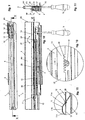
- a drawer system is shown in perspective, which has a body 1, from the interior 1b a drawer 2 is pulled out.
- the front panel 3 at the outer end of the drawer 2 closes when the drawer 2 is closed almost flush with the front end face 1a of the body 1 and is only separated from it via the gap 8 (see FIGS. 3-5).
- the tool 16 for adjusting the front panel 3 is located in the front area of the drawer 2, where also the actuating element 14 (see Figures 9-14) is arranged.
- the inclination of the plane of the front panel 3 with respect to the plane of the end face 1a of the body 1 is suitably changed.
- a height adjustment of the aperture should not be possible or at least imperceptible.
- FIG. 1 shows the drawer system according to FIG. 2 in a side view, partly in section in the lower region.
- the front panel 3 is attached to a rail system 4, which forms the connection to the body 1 on the drawer decor 6 and the carcass angle 5.
- the lifting and lowering element 11 of the diaphragm adjustment device 7 can be seen.
- Figures 3-5 are now enlarged different relative positions of the front panel 3 to the front side 1a of the body 1 is shown, with the gap 8 between them, which holds the two parts 1a and 3 in suitably adjusted case at a distance and typically at 1 to 5 mm is located.
- Figure 3 shows the ideal case (neutral position) of a perfectly adjusted gap 8, so that the planes of the front panel 3 and the end face 1a parallel to each other and therefore do not form a cutting angle 9 with each other.
- FIG. 4 shows the case where the panel 3 is inclined forward at the top so that the gap 8 'is no longer parallel but V-shaped and the planes of the front panel 3 and the front side 1a therefore do not have a positive cutting angle 9' (inclination angle ) of eg 2 degrees form each other. It is easily indicated that in this case the front panel 3 is slightly shifted downwards in comparison to FIG. The gap 8 'has become smaller in the lower region and larger in the upper region, in comparison to the gap 8 of FIG. 3.
- FIG. 5 shows the analogously reversed case of FIG. 4 with a negative cutting angle 9 "of, for example, 3.degree ..
- the front panel 3 is shifted slightly upwards in comparison to FIG. 3 and also to FIG larger and upper in the area, compared to the gap 8 of Figure 3 and also to the gap 8 'of Figure 4.
- the panel 3 touches the body 1 above, so that this represents the maximum adjustment in the direction of the negative cutting angle 9 ".
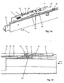
- FIGS. 6-8 now show the effect of raising and lowering the lifting and lowering element 11 for the cases of FIGS. 3-5, wherein FIG. 6 corresponds to the situation according to FIG. 3, FIG. 7 to FIG. 4 and FIG 8 of FIG. 5.
- the lifting and lowering element 11 between the drawer rail 10 of the rail system 4 and the decorative profile 6, in particular whose side wall lower part 6c is arranged.
- the lifting and lowering element 11 rests on at least two points on the drawer rail 10 and rises in at least one area roof-shaped upwards, passes through a narrow guide opening 12 in the decor 6 and the side wall lower part 6c up through, occurs in Distance therefrom through a further wider opening in the decor 6 or its side wall lower part 6c again down through and lies down again on the drawer rail 10th
- the distance between the drawer rail 10 and the decor 6 or its side wall lower part 6c is in a middle region, in FIG. 7 this distance is large, in FIG. 8 the distance is small.
- This distance is accomplished by moving the lifting and lowering element 11 in the direction of the longitudinal axis of the drawer rail 10 or the decor 6 or its side wall lower part 6c. There is automatically an increase of the decor 6 or its lower side wall portion 6c when the lifting and lowering element 11 is displaced in the direction of aperture 3, and thus the aperture 3 in FIG. 4 in the lower region approaches the end face 1a of the body 1 drawn.
- the rail system 4 is shown with decorative part 6 in a plan view, wherein the front portion of the decor 6 is shown cut away, and thus gives a view of the actuator 14.
- FIG. 10 shows a view of the section along the line XX of FIG. 9, wherein the side wall 6a, front 6b and the lower part 6c of the decorative part 6 can be seen.
- the front panel 3 not shown here is indirectly or directly attached to the decorative front wall 6b.
- the slide 15 and thus the lifting and lowering element 11 then pushes towards the front panel 3 or moves away from it, so that the distance between the drawer rail 10 and the decor 6 or side wall lower part 6c of the decor 6 is reduced or increased, whereby mainly the inclination angle 8 between the planes of the front panel 3 and the end face 1a of the body 1 changes.
- the passage of the slide 15 through the recess 30 of the decor 6 or its lower part 6c onto the drawer rail 10 can still be seen in FIG. 10, which recess 30 is arranged in front of the lifting and lowering element 11.
- FIG. 11 shows the side view from the right in the direction of arrow XI of FIG. 10, where the rail system 4 can be seen better, consisting of the aforementioned drawer rail 10, on which the decor 6 rests and rests, on which decor 6 the drawer itself attached with front 3, bottom and back.
- the drawer rail 10 is connected, as usual, via roller means to a middle rail 17, which in turn is connected by further roller means to the carcass rail 18, on which the two carcass angles are located, with which the drawer 2 is connected to the carcass 1.
- the invention can also be used in partial extracts without middle rail.
- two rail systems 4 are provided on the left and right thereof.
- the slide 15 rests partly on the upper side of the drawer rail 10 and partly on the decorative lower part 6c.
- the slide 15 consists of the actuating element 14 which is arranged in the region of the panel 3 and which is rigidly connected via a connecting element 28 to the lifting and lowering element 11 located close to the body rear wall.
- the actuating element 14 extends in the region between the front panel 3 and the beginning of the drawer rail 10, merges into the connecting element 28, which defines a virtual pivot axis 24 on the front edge to the drawer rail 10 and into the rear area of the drawer rail 10 on the decorative Lower part 6c rests.
- the distance between the drawer rail 10 and decor 6 changes at all points except on the pivot axis 24, but in particular on the lifting and lowering element 11, which is the trigger for the lifting or lowering process.
- the distance of the n extension of the longitudinal axis of the drawer rail 10 to the decor 6 changes to a small extent on the front panel 3, whereby the front panel 3 is slightly raised or lowered.
- the drawer rail 10 together with the remaining rails 17, 18 remain unaffected and in their initial position, e.g. in a horizontal position.
- FIG. 12 shows an enlarged detail of the penetration of the lifting and lowering element 11 through the decor 6.
- the lifting and lowering element 11 is guided tightly in the guide 12, in which case the inclined ramps of the guide 12 of the decoration 6 can then slide up and down via the guide slope 11a.
- the guide slope 11a of the slider 15 connects to the top of the plateau 11b, which fulfills only the purpose of ensuring a connection to the downwardly sloping support ramp 11c again, which is supported on the drawer rail 10.
- Figure 13 shows an enlarged detail of the support of the actuating element 14 on the lower part 6c of the decor 6.
- the teeth 19 in the side region of the actuating element 14 can be seen, in which the tool with its tip (here cross slot) engages and thereby the torque of the tool in a linear movement of the slider 15 is implemented.
- Figure 14 shows a perspective view of the displacement mechanism in the region of the actuating element 14 of the slider 15.
- the flat slider 15 is slidably mounted on the lower part 6c of the decorative side wall 6a in guide lugs 20.
- the guide tabs 20 allow sliding of the slider 15 in the direction of the longitudinal axis of the drawer rail 10, but prevent shifting transversely horizontally or optionally vertically thereto.
- the cross-hole screwdriver 16 engages from below into the lateral toothing 19 of the slider 15. With a corrugation 21 between the slider 15 and the lower part 6c, the longitudinal movement can be latched.
- Figure 15 shows how the slider 15 is bent from a band of metal or plastic to a wedge-shaped sliding piece 11, which projects through a notch 22 in the decorative base 6c upwards and which slidably rests with one side on the drawer rail 10 and with its inclined to the drawer front side (direction panel 3) wedge surface 11a on an oblique guide nose 23 of the side wall lower part 6c is supported.
- the slide movement to the rear in the direction of the rear wall of the body 1 causes a lowering of the side wall 6c and thus the drawer 2 and vice versa.
- a laterally supporting guide tab 20 is arranged on the drawer rail 10, which penetrates a slot of the wedge 11.
- Figure 16 is the enlarged side view of Figure 15 in the direction XVI, where once again the arrangement between the slider 15 between upper decor 6 and lower drawer rail 10 is illustrated.
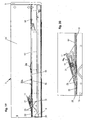
- FIGS. 17 and 18 show schematic diagrams of how the pivoting of the drawer 2 and of the decor 6 or its lower part 6c takes place by lifting / lowering the lifting and lowering element 11 and what effects this has on the stroke or lowering of the front panel 3 ,
- Figure 17 illustrates the state of the art according to nearest AT 409 067 B and DE 44014 462 A1
- Figure 18 illustrates the present invention.
- a stroke or lowering by the lifting and lowering element 11 by the amount 26 causes a pivoting of the drawer 2 and the decor 6 or its lower part 6 c about the pivot axis 24 in the pivot directions 29 by the angle 25th (For example, 5 degrees), in the positions 2 ', 6' and a pivoting of the aperture 3 by the inclination angle 9 between the aperture 3 and end face 1a of the body 1 in the position 3 '.
- the angle amount 25 corresponds to the angle of inclination 9 between the aperture 3 'and end face 1a of the body 1.
- the stroke-lowering amounts 26 and angle amounts 27 in the prior art and in the present invention are assumed to be identical.
- the amount 27 of the lifting or lowering of the aperture 3 is greater than the amount of lifting or lowering of the stroke - And lowering 11, with about a gear ratio greater than 1, depending on lever ratios, in the figures 1.25 and 1.5.
- the lifting and lowering element 11 is each a little closer to the pivot axis 24 than the diaphragm 3, so that the deflection of the lifting and lowering element 11 always has a positive gain (translation) of the deflection of the diaphragm 3 result.
- the arrangement of the prior art is completely different, since the lifting and lowering element 11 is farther away from the pivot axis 24 than the diaphragm 3, so that the deflection of the lifting and lowering element 11 is always a negative gain (reduction) the deflection of the aperture 3 result.
- the pivot axis 24 is seated on the front edge of the drawer rail 10 and the lifting and lowering 11th in the rear area of the decor 6, but not at the maximum rear, so that a reduction ratio of about 0.3 results.
- 3 mm Height excursion 24 on the lifting and lowering element 11 then result in about 1 mm height deflection 27 on the diaphragm 3 ', wherein in the prior art, about 4 mm height deflection 27 would adjust to the diaphragm 3', that is 4 times as much.
- the unwanted height deflection 27 does not play a significant role and can therefore be neglected.
- a simple and rapid tilt adjustment of the angle 9 of the diaphragm 3 is possible, with only one aperture adjusting device 7, which leads to reduced manufacturing and assembly costs.
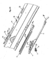
- FIG. 19 shows a side view of a drawer with another embodiment of a diaphragm adjustment device, wherein FIG. 20 shows an enlarged view of the lifting and lowering element 11 of the diaphragm adjustment device according to FIG. 19.
- FIG. 20 shows an enlarged view of the lifting and lowering element 11 of the diaphragm adjustment device according to FIG. 19.
- An exploded perspective view of the diaphragm adjustment device according to FIG. 19 is shown in FIG.
- the individual parts of the aperture adjustment can be seen, which consists of an adjusting element 31 in the form of a screw with gear 35, a slider 15 with lifting and lowering 11 with guide ramp 11a, a strip-shaped rocker 32 with guide wings 32a and guide track 32b , and from a notch 22 from the lower part 6c of the decorative profile 6, with guide lugs 23rd
- the lifting and lowering element 11 now engages from below (FIG. 21) into the longitudinal slot of the guide track 32b and is displaceably guided in its length. Furthermore, the lifting and lowering element 11 passes through the notch 22 on the upper side of the lower part 6 c of the decorative profile 6 and the guide ramp 11 a is guided between the guide lugs 23 on the notch 22.
- the rocker 32 is in this case between the slider 15 and the decorative base 6c and the wings 32a of the rocker 32 pass through for lateral stabilization openings 36 in the decorative base 6c.
- a front Bogenendteil 38 passes through a further opening 37 in the decorative lower part 6c and rests on the surface of the decorative base 6c and can be moved longitudinally there, so that the Bogenendteil 38 is a guiding and supporting means of the slider 15 and the rocker 32.
- the slider 15 shown in Fig. 21 and the rocker 32 are fixed by the leadership of the guide ramp 11a between the guide lugs 23 on the notch 22 on the decorative base 6c, but also by the support of the Bogenendteils 38 on the decorative base 6c.
- the adjusting element 31 is stationary and rotatable on the inner side of the decorative profile 6 (bottom 6c) and engages with its pin 39 in the recess 40 of a tab 41 at the edge of the notch 22 a. With its gear 35, the adjusting element 31 engages in the toothing 19 of the lifting and lowering element 11, which is designed in particular as a plastic part.
- the lifting and lowering element 11 of the slider 15 engages in a guide track 32b of the rocker 32 and can be moved axially in this.
- the rocker 32 is guided with at least two wings 32a in the lower part 6c of the decor 6 and in particular formed as a sheet-metal part.
- the position of the actuating element 14, 31 is possible not only in the front region of the drawer (FIGS. 1-18), but also in the rear region (FIGS. 19-21).
- the actuator 31 in the rear part of the drawer is reached with the drawer pulled over the interior, so that the drawer must be emptied before.
Landscapes
- Drawers Of Furniture (AREA)
- Operating, Guiding And Securing Of Roll- Type Closing Members (AREA)
- Shutter-Related Mechanisms (AREA)
Claims (17)
- Dispositif de réglage de panneau pour un tiroir (2) qui est équipé d'un panneau frontal (3) et qui, est guidé longitudinalement dans un corps de meuble (1), des deux côtés, grâce à un système de rails (4) comprenant au moins un rail de tiroir (10), un rail de corps de meuble (18) et à titre optionnel un profilé de décor (6), le dispositif de réglage de panneau étant apte à modifier l'angle d'inclinaison (9) défini entre le plan vertical du côté frontal avant (1a) du corps de meuble (1) et le plan vertical du panneau frontal (3) du tiroir (2), et agissant directement ou indirectement entre le tiroir (2) et le rail de tiroir (10) grâce à un dispositif de soulèvement ou d'abaissement (15, 12 ; 23) comportant un élément de soulèvement et d'abaissement (11), de manière à permettre un pivotement du tiroir (2) et, ainsi, du panneau (3) sur un pivot (24), caractérisé en ce que le pivot (24) s'étend entre le panneau frontal (3) et l'élément de soulèvement et d'abaissement (11), et la distance entre le pivot (24) et le panneau frontal (3) est à peu près égale ou inférieure à la distance entre le pivot (24) et l'élément de soulèvement et d'abaissement (11).
- Dispositif de réglage de panneau selon la revendication 1, caractérisé en ce que le pivot (24) est disposé le plus près possible du panneau frontal et/ou l'élément de soulèvement et d'abaissement (11) du dispositif de soulèvement et d'abaissement (15, 12 ; 23) est disposé le plus loin possible du pivot (24).
- Dispositif de réglage de panneau selon la revendication 1 ou 2, caractérisé en ce que le pivot (24) se trouve sur le rail de tiroir (10), et l'élément de soulèvement et d'abaissement (11) du dispositif de soulèvement et d'abaissement (15, 12 ; 23) dans la zone arrière du décor de tiroir (6), en particulier sur la partie inférieure (6c) de celui-ci.
- Dispositif de réglage de panneau selon l'une des revendications précédentes, caractérisé en ce que le dispositif de soulèvement et d'abaissement (15, 12 ; 23) contient un coulisseau (15) qui contient lui-même l'élément de soulèvement et d'abaissement (11), un élément d'actionnement (14 ; 31) pour celui-ci et un élément de liaison (28 ; 35), l'élément de soulèvement et d'abaissement (11) étant disposé dans la zone arrière du tiroir (2) qui est reliée grâce à l'élément de liaison (28) à l'élément d'actionnement (14) disposé dans la zone avant du tiroir (2) ou qui est reliée par l'élément de liaison (35) à l'élément d'actionnement (31) disposé dans la zone arrière du tiroir (2).
- Dispositif de réglage de panneau selon la revendication 4, caractérisé en ce que l'élément d'actionnement (14 ; 31) pour l'élément de soulèvement et d'abaissement (11) est disposé sur le tiroir (2) lui-même ou sur le décor (6) de celui-ci, et l'élément de soulèvement et d'abaissement (11) est disposé sur le rail de tiroir (10), le coulisseau (15) traversant le tiroir (2) ou le décor (6) de celui-ci sur sa trajectoire menant dans la zone arrière du tiroir (2).
- Dispositif de réglage de panneau selon la revendication 4 ou 5, caractérisé en ce que les surfaces d'appui du tiroir (2) ou de le décor (6) de celui-ci, et du rail de tiroir (10) pour le coulisseau (15) sont à peu près horizontales et sont dirigées vers le haut.
- Dispositif de réglage de panneau selon l'une des revendications 4 à 6, caractérisé en ce que le coulisseau (15) se compose d'un matériau plat en forme de bande ou de fil et est en métal ou en matière plastique.
- Dispositif de réglage de panneau selon l'une des revendications 4 à 7, caractérisé en ce que le coulisseau (15) est réalisé d'une seule pièce avec son élément de soulèvement et d'abaissement (11), son élément de liaison (28) et son élément d'actionnement (14).
- Dispositif de réglage de panneau selon l'une des revendications 4 à 8, caractérisé en ce que l'élément d'actionnement (14) du coulisseau (15) présente une denture (19) dans laquelle un outil (16) vient en prise lors du réglage de l'angle d'inclinaison (9).
- Dispositif de réglage de panneau selon la revendication 9, caractérisé en ce que la denture (19) est prévue dans la surface latérale de l'élément d'actionnement (14).
- Dispositif de réglage de panneau selon l'une des revendications 4 à 10, caractérisé en ce que tout le coulisseau (15) ou des parties seulement de celui-ci sont guidés dans des pattes de guidage (20) sur le rail de tiroir (10) et/ou sur le tiroir (2) ou sur le profilé de décor (6) de celui-ci, ces pattes de guidage (20) formant un guide horizontal et éventuellement aussi vertical qui permet toujours un déplacement dans l'axe longitudinal des rails (4), mais pas transversalement par rapport à celui-ci.
- Dispositif de réglage de panneau selon l'une au moins des revendications précédentes, caractérisé en ce que pour maintenir la position relative réglée entre le tiroir (2) ou son décor (6) et le rail de tiroir (10), le dispositif de réglage de panneau est équipé d'un dispositif d'eneliquetage.
- Dispositif de réglage de panneau selon la revendication 12, caractérisé en ce que ce dispositif d'encliquetage est prévu sous la forme de cannelures autobloquantes (21), transversalement et/ou en biais par rapport au sens de coulissement du tiroir (2).
- Dispositif de réglage de panneau selon la revendication 13, caractérisé en ce que les cannelures (21) sont disposées dans la zone de l'élément d'actionnement (14) de l'élément de soulèvement et d'abaissement (11).
- Dispositif de réglage de panneau selon l'une des revendications 4 à 14, caractérisé en ce que des limitations par butées appropriées sont prévues sur le tiroir (2) et/ou sur le décor (6) et/ou sur le rail de tiroir (10) pour que le coulisseau (15), lors de son déplacement dans le sens longitudinal des rails (4), ne puisse pas être tiré hors de sa position fonctionnelle.
- Dispositif de réglage de panneau selon l'une des revendications 4 à 15, caractérisé en ce que le coulisseau (15) se compose d'un matériau plat qui s'étend de la zone avant jusque dans la zone arrière du rail de guidage et qui est monté pour pouvoir coulisser sur la branche horizontale de la partie inférieure de paroi latérale (6c) de la zone avant jusqu'au-delà de la zone centrale, et qui s'appuie dans la zone arrière sur le rail de tiroir (10), l'extrémité du coulisseau (15) étant déformée pour former la pièce coulissante en forme de coin (11).
- Dispositif de réglage de panneau selon la revendication 16, caractérisé en ce que le coulisseau (15) est coudé un peu avant la pièce coulissante en forme de coin (11), dans son extension longitudinale, et passe à travers un creux (30) prévu dans la branche horizontale de la partie inférieure de paroi latérale pour s'appuyer sur le rail de tiroir (10).
Applications Claiming Priority (2)
| Application Number | Priority Date | Filing Date | Title |
|---|---|---|---|
| DE10254772A DE10254772A1 (de) | 2002-11-22 | 2002-11-22 | Blendeneinstellvorrichtung |
| DE10254772 | 2002-11-22 |
Publications (2)
| Publication Number | Publication Date |
|---|---|
| EP1421876A1 EP1421876A1 (fr) | 2004-05-26 |
| EP1421876B1 true EP1421876B1 (fr) | 2006-01-25 |
Family
ID=32185925
Family Applications (1)
| Application Number | Title | Priority Date | Filing Date |
|---|---|---|---|
| EP03026771A Expired - Lifetime EP1421876B1 (fr) | 2002-11-22 | 2003-11-21 | Dispositif de réglage d'une façade frontale pour tiroirs |
Country Status (4)
| Country | Link |
|---|---|
| US (1) | US7244006B2 (fr) |
| EP (1) | EP1421876B1 (fr) |
| AT (1) | ATE316346T1 (fr) |
| DE (2) | DE10254772A1 (fr) |
Cited By (1)
| Publication number | Priority date | Publication date | Assignee | Title |
|---|---|---|---|---|
| DE102010016176A1 (de) * | 2010-03-29 | 2011-09-29 | Paul Hettich Gmbh & Co. Kg | Vorrichtung zur Neigungsverstellung einer Frontblende |
Families Citing this family (17)
| Publication number | Priority date | Publication date | Assignee | Title |
|---|---|---|---|---|
| WO2004110213A2 (fr) * | 2003-05-13 | 2004-12-23 | Grass America Inc. | Dispositif de verrouillage avant pour mettre en prise de maniere liberable un tiroir avec une glissiere de tiroir |
| US8016374B2 (en) * | 2005-11-10 | 2011-09-13 | Grass Gmbh | Pull-out slide for drawers and drawer |
| DE202007017999U1 (de) * | 2007-12-22 | 2009-04-30 | Paul Hettich Gmbh & Co. Kg | Frontverstellung für Schubkästen und Schubkasten |
| TWI346532B (en) * | 2008-03-21 | 2011-08-11 | King Slide Works Co Ltd | Slide adjusting device for use in a drawer |
| DE202010000086U1 (de) * | 2010-01-27 | 2011-06-01 | Paul Hettich GmbH & Co. KG, 32278 | Schubkasten mit zwei Seitenzargen und einer Frontblende |
| AT509416B1 (de) * | 2010-02-03 | 2012-05-15 | Blum Gmbh Julius | Ausziehführung für eine schublade |
| AT509413B1 (de) * | 2010-02-03 | 2012-12-15 | Blum Gmbh Julius | Neigungsvorrichtung für schubladen |
| DE102010007430A1 (de) * | 2010-02-09 | 2011-08-11 | Heinrich J. Kesseböhmer KG, 49152 | Schrankauszug |
| DE202010012765U1 (de) * | 2010-09-20 | 2012-01-13 | Grass Gmbh | Vorrichtung zur Verstellung der Neigung eines bewegbaren Möbelteils und Möbel |
| DE102010061526A1 (de) * | 2010-12-23 | 2012-06-28 | Paul Hettich Gmbh & Co. Kg | Vorrichtung zur Justierung einer Frontblende |
| DE202010016913U1 (de) * | 2010-12-23 | 2012-03-26 | Grass Gmbh | Möbel mit Vorrichtung zur Anbringung einer Führungseinheit |
| AT511294B1 (de) * | 2011-04-11 | 2013-06-15 | Blum Gmbh Julius | Schubladenausziehführung |
| AT511091B1 (de) * | 2011-04-19 | 2012-09-15 | Blum Gmbh Julius | Schubladenzarge mit neigungsverstellung |
| DE202011005570U1 (de) * | 2011-04-21 | 2014-05-26 | Grass Gmbh | Möbel und Vorrichtung zur Verstellung der Neigung eines Möbelteils |
| TWI605775B (zh) * | 2015-11-12 | 2017-11-21 | 川湖科技股份有限公司 | 抽屜滑軌組件 |
| DE102018130012A1 (de) * | 2018-11-27 | 2020-05-28 | Paul Hettich Gmbh & Co. Kg | Schubkasten und Möbel |
| CN110269416A (zh) * | 2019-07-24 | 2019-09-24 | 洪朝阳 | 一种转屉机构以及柜子 |
Family Cites Families (16)
| Publication number | Priority date | Publication date | Assignee | Title |
|---|---|---|---|---|
| US2928696A (en) * | 1957-06-19 | 1960-03-15 | Hamilton Mfg Co | Drawer tilt adjustment means |
| US3768883A (en) * | 1971-12-27 | 1973-10-30 | Gen Electric | Rack level adjustment system in a dishwasher |
| AT329218B (de) * | 1974-04-01 | 1976-04-26 | Grass Alfred Metallwaren | Schubladenfuhrung |
| DE2851305A1 (de) * | 1978-11-27 | 1980-06-04 | Hettich Paul & Co | Auszugfuehrung fuer schubkaesten |
| AT399086B (de) | 1981-01-29 | 1995-03-27 | Grass Alfred Metallwaren | Verstellvorrichtung für schubladenblenden, insbesondere für küchenmöbelauszüge |
| US4679950A (en) * | 1986-09-22 | 1987-07-14 | Standard Precision, Inc. | Drawer slide with infinite adjustment locking mechanism |
| US4842422A (en) * | 1988-08-25 | 1989-06-27 | Nelson Gary W | Eccentric adjuster for drawer or cabinet track |
| DE3843658A1 (de) * | 1988-12-23 | 1990-07-05 | Grass Ag | Vorrichtung zur einstellung der frontblende bei schubladen |
| DE3930662A1 (de) * | 1989-09-14 | 1991-03-28 | Grass Ag | Frontblende mit verstelleinrichtung |
| AT400214B (de) * | 1991-12-06 | 1995-11-27 | Blum Gmbh Julius | Schublade |
| US5211461A (en) * | 1992-04-10 | 1993-05-18 | Artromick International, Inc. | Vertically adjustable extension drawers |
| AT401713B (de) * | 1993-06-29 | 1996-11-25 | Blum Gmbh Julius | Differentialauszug für schubladen od. dgl. |
| DE4414462B4 (de) * | 1994-04-26 | 2005-03-24 | MEPLA-WERKE LAUTENSCHLäGER GMBH & CO. KG | Beschlag zur Höhenverstellung von Schubladen |
| AT409067B (de) | 2000-03-02 | 2002-05-27 | Blum Gmbh Julius | Ausziehführung für schubladen |
| US6585336B2 (en) * | 2000-10-12 | 2003-07-01 | Sauder Woodworking Co. | Drawer slide having adjustment device |
| TWI249389B (en) * | 2002-06-19 | 2006-02-21 | Salice Arturo Spa | Device for adjusting the height of a drawer |
-
2002
- 2002-11-22 DE DE10254772A patent/DE10254772A1/de not_active Withdrawn
-
2003
- 2003-11-19 US US10/717,256 patent/US7244006B2/en not_active Expired - Fee Related
- 2003-11-21 EP EP03026771A patent/EP1421876B1/fr not_active Expired - Lifetime
- 2003-11-21 AT AT03026771T patent/ATE316346T1/de active
- 2003-11-21 DE DE50302277T patent/DE50302277D1/de not_active Expired - Lifetime
Cited By (1)
| Publication number | Priority date | Publication date | Assignee | Title |
|---|---|---|---|---|
| DE102010016176A1 (de) * | 2010-03-29 | 2011-09-29 | Paul Hettich Gmbh & Co. Kg | Vorrichtung zur Neigungsverstellung einer Frontblende |
Also Published As
| Publication number | Publication date |
|---|---|
| US20040119387A1 (en) | 2004-06-24 |
| EP1421876A1 (fr) | 2004-05-26 |
| ATE316346T1 (de) | 2006-02-15 |
| DE50302277D1 (de) | 2006-04-13 |
| US7244006B2 (en) | 2007-07-17 |
| DE10254772A1 (de) | 2004-06-03 |
Similar Documents
| Publication | Publication Date | Title |
|---|---|---|
| EP1421876B1 (fr) | Dispositif de réglage d'une façade frontale pour tiroirs | |
| EP1550385B1 (fr) | Dispositif de réglage de la hauteur d'un tiroir | |
| AT508544B1 (de) | Kupplungsvorrichtung zum lösbaren verbinden einer schublade mit einer bewegbaren schiene | |
| EP3491966B1 (fr) | Dispositif de raccordement et meuble ou appareil électroménager | |
| WO2020232489A1 (fr) | Système de guidage pour guider au moins un battant de porte | |
| EP1275541B1 (fr) | Module, spécialement module coulissant pour véhicule | |
| EP2774509A1 (fr) | Dispositif d'orientation d'une façade de mobilier mobile | |
| EP3684223B1 (fr) | Dispositif d'accouplement destiné à un tiroir à encliquetage postérieur | |
| EP1336709A1 (fr) | Dispositif de verrouillage pour empêcher l'ouverture simultanée de tiroirs superposés | |
| DE102018130016A1 (de) | Schiebedachsystem für ein Kraftfahrzeug | |
| EP4243652B1 (fr) | Guide d'extraction | |
| EP1834544A1 (fr) | Verrouillage pour tables de ping-pong dotée de demi-panneaux pivotants | |
| DE102014104135B4 (de) | Auszugsführung für einen Schubkasten | |
| EP3923767B1 (fr) | Tiroir | |
| EP4680821A1 (fr) | Ferrure de porte coulissante et agencement de porte coulissante correspondant | |
| EP3112763A1 (fr) | Hotte aspirante avec écran d'extraction coulissant | |
| EP3897295A1 (fr) | Dispositif d'autodéploiement | |
| DE202017105849U1 (de) | Liftbeschlag für einen Möbelauszug | |
| AT518048B1 (de) | Schubladenwand | |
| EP2618698B1 (fr) | Dispositif de réglage de l'inclinaison d'une partie de meuble mobile, et meuble correspondant | |
| EP1288043A2 (fr) | Dispositif de toit coulissant | |
| DE102023111975B4 (de) | Auszugsführung für ein Schubelement eines Möbels mit einer Höheneinstellvorrichtung | |
| DE20211803U1 (de) | Vorrichtung zur Höhenverstellung einer Schublade | |
| EP4111908B1 (fr) | Cadre de tiroir pourvu d'adaptateurs pour différentes largeurs de pose | |
| DE9301344U1 (de) | Vollauszug für Schubladen |
Legal Events
| Date | Code | Title | Description |
|---|---|---|---|
| PUAI | Public reference made under article 153(3) epc to a published international application that has entered the european phase |
Free format text: ORIGINAL CODE: 0009012 |
|
| AK | Designated contracting states |
Kind code of ref document: A1 Designated state(s): AT BE BG CH CY CZ DE DK EE ES FI FR GB GR HU IE IT LI LU MC NL PT RO SE SI SK TR |
|
| AX | Request for extension of the european patent |
Extension state: AL LT LV MK |
|
| 17P | Request for examination filed |
Effective date: 20040812 |
|
| AKX | Designation fees paid |
Designated state(s): AT BE BG CH CY CZ DE DK EE ES FI FR GB GR HU IE IT LI LU MC NL PT RO SE SI SK TR |
|
| GRAP | Despatch of communication of intention to grant a patent |
Free format text: ORIGINAL CODE: EPIDOSNIGR1 |
|
| GRAS | Grant fee paid |
Free format text: ORIGINAL CODE: EPIDOSNIGR3 |
|
| GRAA | (expected) grant |
Free format text: ORIGINAL CODE: 0009210 |
|
| AK | Designated contracting states |
Kind code of ref document: B1 Designated state(s): AT BE BG CH CY CZ DE DK EE ES FI FR GB GR HU IE IT LI LU MC NL PT RO SE SI SK TR |
|
| PG25 | Lapsed in a contracting state [announced via postgrant information from national office to epo] |
Ref country code: IT Free format text: LAPSE BECAUSE OF FAILURE TO SUBMIT A TRANSLATION OF THE DESCRIPTION OR TO PAY THE FEE WITHIN THE PRESCRIBED TIME-LIMIT;WARNING: LAPSES OF ITALIAN PATENTS WITH EFFECTIVE DATE BEFORE 2007 MAY HAVE OCCURRED AT ANY TIME BEFORE 2007. THE CORRECT EFFECTIVE DATE MAY BE DIFFERENT FROM THE ONE RECORDED. Effective date: 20060125 Ref country code: GB Free format text: LAPSE BECAUSE OF FAILURE TO SUBMIT A TRANSLATION OF THE DESCRIPTION OR TO PAY THE FEE WITHIN THE PRESCRIBED TIME-LIMIT Effective date: 20060125 Ref country code: IE Free format text: LAPSE BECAUSE OF FAILURE TO SUBMIT A TRANSLATION OF THE DESCRIPTION OR TO PAY THE FEE WITHIN THE PRESCRIBED TIME-LIMIT Effective date: 20060125 Ref country code: RO Free format text: LAPSE BECAUSE OF FAILURE TO SUBMIT A TRANSLATION OF THE DESCRIPTION OR TO PAY THE FEE WITHIN THE PRESCRIBED TIME-LIMIT Effective date: 20060125 Ref country code: SI Free format text: LAPSE BECAUSE OF FAILURE TO SUBMIT A TRANSLATION OF THE DESCRIPTION OR TO PAY THE FEE WITHIN THE PRESCRIBED TIME-LIMIT Effective date: 20060125 Ref country code: FI Free format text: LAPSE BECAUSE OF FAILURE TO SUBMIT A TRANSLATION OF THE DESCRIPTION OR TO PAY THE FEE WITHIN THE PRESCRIBED TIME-LIMIT Effective date: 20060125 Ref country code: NL Free format text: LAPSE BECAUSE OF FAILURE TO SUBMIT A TRANSLATION OF THE DESCRIPTION OR TO PAY THE FEE WITHIN THE PRESCRIBED TIME-LIMIT Effective date: 20060125 Ref country code: SK Free format text: LAPSE BECAUSE OF FAILURE TO SUBMIT A TRANSLATION OF THE DESCRIPTION OR TO PAY THE FEE WITHIN THE PRESCRIBED TIME-LIMIT Effective date: 20060125 |
|
| REG | Reference to a national code |
Ref country code: GB Ref legal event code: FG4D Free format text: NOT ENGLISH |
|
| REG | Reference to a national code |
Ref country code: CH Ref legal event code: EP |
|
| REG | Reference to a national code |
Ref country code: IE Ref legal event code: FG4D Free format text: LANGUAGE OF EP DOCUMENT: GERMAN |
|
| REF | Corresponds to: |
Ref document number: 50302277 Country of ref document: DE Date of ref document: 20060413 Kind code of ref document: P |
|
| PG25 | Lapsed in a contracting state [announced via postgrant information from national office to epo] |
Ref country code: DK Free format text: LAPSE BECAUSE OF FAILURE TO SUBMIT A TRANSLATION OF THE DESCRIPTION OR TO PAY THE FEE WITHIN THE PRESCRIBED TIME-LIMIT Effective date: 20060425 Ref country code: BG Free format text: LAPSE BECAUSE OF FAILURE TO SUBMIT A TRANSLATION OF THE DESCRIPTION OR TO PAY THE FEE WITHIN THE PRESCRIBED TIME-LIMIT Effective date: 20060425 Ref country code: SE Free format text: LAPSE BECAUSE OF FAILURE TO SUBMIT A TRANSLATION OF THE DESCRIPTION OR TO PAY THE FEE WITHIN THE PRESCRIBED TIME-LIMIT Effective date: 20060425 |
|
| PG25 | Lapsed in a contracting state [announced via postgrant information from national office to epo] |
Ref country code: ES Free format text: LAPSE BECAUSE OF FAILURE TO SUBMIT A TRANSLATION OF THE DESCRIPTION OR TO PAY THE FEE WITHIN THE PRESCRIBED TIME-LIMIT Effective date: 20060506 |
|
| PG25 | Lapsed in a contracting state [announced via postgrant information from national office to epo] |
Ref country code: PT Free format text: LAPSE BECAUSE OF FAILURE TO SUBMIT A TRANSLATION OF THE DESCRIPTION OR TO PAY THE FEE WITHIN THE PRESCRIBED TIME-LIMIT Effective date: 20060626 |
|
| NLV1 | Nl: lapsed or annulled due to failure to fulfill the requirements of art. 29p and 29m of the patents act | ||
| GBV | Gb: ep patent (uk) treated as always having been void in accordance with gb section 77(7)/1977 [no translation filed] |
Effective date: 20060125 |
|
| REG | Reference to a national code |
Ref country code: IE Ref legal event code: FD4D |
|
| PG25 | Lapsed in a contracting state [announced via postgrant information from national office to epo] |
Ref country code: MC Free format text: LAPSE BECAUSE OF NON-PAYMENT OF DUE FEES Effective date: 20061130 Ref country code: BE Free format text: LAPSE BECAUSE OF NON-PAYMENT OF DUE FEES Effective date: 20061130 |
|
| PLBE | No opposition filed within time limit |
Free format text: ORIGINAL CODE: 0009261 |
|
| STAA | Information on the status of an ep patent application or granted ep patent |
Free format text: STATUS: NO OPPOSITION FILED WITHIN TIME LIMIT |
|
| 26N | No opposition filed |
Effective date: 20061026 |
|
| BERE | Be: lapsed |
Owner name: GRASS GMBH Effective date: 20061130 |
|
| PG25 | Lapsed in a contracting state [announced via postgrant information from national office to epo] |
Ref country code: FR Free format text: LAPSE BECAUSE OF FAILURE TO SUBMIT A TRANSLATION OF THE DESCRIPTION OR TO PAY THE FEE WITHIN THE PRESCRIBED TIME-LIMIT Effective date: 20070316 Ref country code: CZ Free format text: LAPSE BECAUSE OF FAILURE TO SUBMIT A TRANSLATION OF THE DESCRIPTION OR TO PAY THE FEE WITHIN THE PRESCRIBED TIME-LIMIT Effective date: 20060125 Ref country code: GR Free format text: LAPSE BECAUSE OF FAILURE TO SUBMIT A TRANSLATION OF THE DESCRIPTION OR TO PAY THE FEE WITHIN THE PRESCRIBED TIME-LIMIT Effective date: 20060426 |
|
| PG25 | Lapsed in a contracting state [announced via postgrant information from national office to epo] |
Ref country code: EE Free format text: LAPSE BECAUSE OF FAILURE TO SUBMIT A TRANSLATION OF THE DESCRIPTION OR TO PAY THE FEE WITHIN THE PRESCRIBED TIME-LIMIT Effective date: 20060125 |
|
| PG25 | Lapsed in a contracting state [announced via postgrant information from national office to epo] |
Ref country code: TR Free format text: LAPSE BECAUSE OF FAILURE TO SUBMIT A TRANSLATION OF THE DESCRIPTION OR TO PAY THE FEE WITHIN THE PRESCRIBED TIME-LIMIT Effective date: 20060125 Ref country code: LI Free format text: LAPSE BECAUSE OF NON-PAYMENT OF DUE FEES Effective date: 20071130 Ref country code: LU Free format text: LAPSE BECAUSE OF NON-PAYMENT OF DUE FEES Effective date: 20061121 Ref country code: CH Free format text: LAPSE BECAUSE OF NON-PAYMENT OF DUE FEES Effective date: 20071130 Ref country code: HU Free format text: LAPSE BECAUSE OF FAILURE TO SUBMIT A TRANSLATION OF THE DESCRIPTION OR TO PAY THE FEE WITHIN THE PRESCRIBED TIME-LIMIT Effective date: 20060726 |
|
| REG | Reference to a national code |
Ref country code: CH Ref legal event code: PL |
|
| PG25 | Lapsed in a contracting state [announced via postgrant information from national office to epo] |
Ref country code: CY Free format text: LAPSE BECAUSE OF FAILURE TO SUBMIT A TRANSLATION OF THE DESCRIPTION OR TO PAY THE FEE WITHIN THE PRESCRIBED TIME-LIMIT Effective date: 20060125 Ref country code: FR Free format text: LAPSE BECAUSE OF FAILURE TO SUBMIT A TRANSLATION OF THE DESCRIPTION OR TO PAY THE FEE WITHIN THE PRESCRIBED TIME-LIMIT Effective date: 20060125 |
|
| PGFP | Annual fee paid to national office [announced via postgrant information from national office to epo] |
Ref country code: AT Payment date: 20181121 Year of fee payment: 16 |
|
| PGFP | Annual fee paid to national office [announced via postgrant information from national office to epo] |
Ref country code: IT Payment date: 20181126 Year of fee payment: 16 |
|
| PGFP | Annual fee paid to national office [announced via postgrant information from national office to epo] |
Ref country code: DE Payment date: 20191008 Year of fee payment: 17 |
|
| REG | Reference to a national code |
Ref country code: AT Ref legal event code: MM01 Ref document number: 316346 Country of ref document: AT Kind code of ref document: T Effective date: 20191121 |
|
| PG25 | Lapsed in a contracting state [announced via postgrant information from national office to epo] |
Ref country code: IT Free format text: LAPSE BECAUSE OF NON-PAYMENT OF DUE FEES Effective date: 20191121 |
|
| PG25 | Lapsed in a contracting state [announced via postgrant information from national office to epo] |
Ref country code: AT Free format text: LAPSE BECAUSE OF NON-PAYMENT OF DUE FEES Effective date: 20191121 |
|
| REG | Reference to a national code |
Ref country code: DE Ref legal event code: R119 Ref document number: 50302277 Country of ref document: DE |
|
| PG25 | Lapsed in a contracting state [announced via postgrant information from national office to epo] |
Ref country code: DE Free format text: LAPSE BECAUSE OF NON-PAYMENT OF DUE FEES Effective date: 20210601 |