EP0699449A1 - Injecteur et son utilisation - Google Patents
Injecteur et son utilisation Download PDFInfo
- Publication number
- EP0699449A1 EP0699449A1 EP93924803A EP93924803A EP0699449A1 EP 0699449 A1 EP0699449 A1 EP 0699449A1 EP 93924803 A EP93924803 A EP 93924803A EP 93924803 A EP93924803 A EP 93924803A EP 0699449 A1 EP0699449 A1 EP 0699449A1
- Authority
- EP
- European Patent Office
- Prior art keywords
- needle
- injection
- aforementioned
- distal end
- connector portion
- Prior art date
- Legal status (The legal status is an assumption and is not a legal conclusion. Google has not performed a legal analysis and makes no representation as to the accuracy of the status listed.)
- Granted
Links
Images



Classifications
-
- A—HUMAN NECESSITIES
- A61—MEDICAL OR VETERINARY SCIENCE; HYGIENE
- A61M—DEVICES FOR INTRODUCING MEDIA INTO, OR ONTO, THE BODY; DEVICES FOR TRANSDUCING BODY MEDIA OR FOR TAKING MEDIA FROM THE BODY; DEVICES FOR PRODUCING OR ENDING SLEEP OR STUPOR
- A61M5/00—Devices for bringing media into the body in a subcutaneous, intra-vascular or intramuscular way; Accessories therefor, e.g. filling or cleaning devices, arm-rests
- A61M5/178—Syringes
- A61M5/31—Details
- A61M5/32—Needles; Details of needles pertaining to their connection with syringe or hub; Accessories for bringing the needle into, or holding the needle on, the body; Devices for protection of needles
-
- A—HUMAN NECESSITIES
- A61—MEDICAL OR VETERINARY SCIENCE; HYGIENE
- A61B—DIAGNOSIS; SURGERY; IDENTIFICATION
- A61B17/00—Surgical instruments, devices or methods
- A61B17/34—Trocars; Puncturing needles
- A61B17/3401—Puncturing needles for the peridural or subarachnoid space or the plexus, e.g. for anaesthesia
-
- A—HUMAN NECESSITIES
- A61—MEDICAL OR VETERINARY SCIENCE; HYGIENE
- A61M—DEVICES FOR INTRODUCING MEDIA INTO, OR ONTO, THE BODY; DEVICES FOR TRANSDUCING BODY MEDIA OR FOR TAKING MEDIA FROM THE BODY; DEVICES FOR PRODUCING OR ENDING SLEEP OR STUPOR
- A61M5/00—Devices for bringing media into the body in a subcutaneous, intra-vascular or intramuscular way; Accessories therefor, e.g. filling or cleaning devices, arm-rests
- A61M5/178—Syringes
- A61M5/31—Details
- A61M5/315—Pistons; Piston-rods; Guiding, blocking or restricting the movement of the rod or piston; Appliances on the rod for facilitating dosing ; Dosing mechanisms
- A61M5/31525—Dosing
- A61M5/31531—Microsyringes, e.g. having piston bore diameter close or equal to needle shaft diameter
Definitions
- FIG. 8 A known technique for injecting chymopapain for such purposes as the treatment of herniated intervertebral disks in dogs is depicted by rough sketch in Fig. 8 and comprises the following steps: an injection needle 52 that has an inner needle (mandolin) 51 inserted therein is allowed to pierce through the skin 61 and then muscle 62 so that its distal end reaches the vertebral pulp 64 in an intervertebral disk 63 (Fig.
- the vertebral pulp 64 in the intervertebral disk 63 is a closed space surrounded with a fibrous ring 66 and it is located at a comparatively deep site in the body; hence, in order to assure penetration through the skin 61, muscle 62 and even the fibrous ring 66, the injection needle 52 must have a reasonable thickness and, at the same time, it is necessary to use the spacer inner needle 51 so that the injection needle 52 will neither bend nor undergo obstruction by tissue fragments during piercing.
- the injection needle 52 is handled as a separate member from the injection barrel 54 in the current method and when the needle tip has reached the intended site, the inner needle 51 is withdrawn and the injection barrel 54 is connected.
- the means of coupling the lure lock 55 to the drug filled connector 53 it is impossible to avoid inaccuracy in the dose of drug to be injected. What is more, complete rejection of air is difficult to achieve by the means of connecting the injection barrel after the connector 53 is filled with the drug and any residual air will cause further inaccuracy in the dose of drug to be injected.
- the present invention provides (1) an injection tool characterized by comprising an injection device comprising an injection barrel and an injection needle that is to be mounted at the distal end thereof, a piercing hollow needle having a connector portion that is to be connected to the aforementioned injection device and a needle portion that allows the aforementioned injection needle to be inserted almost tightly, and an inner needle having a basal portion that is to be fitted tightly in the aforementioned connector portion and a solid needle that is to be inserted almost tightly in the aforementioned needle portion, and (2) a method of using an injection tool that is characterized in that a solid needle is inserted almost tightly in the needle portion of a piercing hollow needle having a connector portion that is to be connected to an injection device comprising an injection barrel and an injection needle mounted at the distal end thereof and said needle portion that enables the injection needle of the aforementioned injection device to be inserted therethrough almost tightly and, at the same time, the aforementioned needle portion is allowed to pierce to a predetermined site in the body of interest with an inner needle having
- the injection tool of the present invention comprises an injection device, a piercing hollow needle and an inner needle, with its basic structure being such as to permit injection of drugs and the like by a conventional method of injection, and it is characterized in that a mechanism that establishes connection between the piercing hollow needle and the connector portion is provided on the injection device, which mechanism allows the position of the tip of the injection needle to be restricted by the needle portion of the piercing hollow needle so as to ensure easy and accurate injection.
- the piercing hollow needle which is comparatively thick and rugged and which has the solid needle inserted for reinforcement and for closing the hollow portion is preliminarily forced to reach the neighborhood of the intended site and, thereafter, the injection needle of the injection device is inserted through the interior of said hollow needle; hence, even if said injection needle used is comparatively thin and has low strength, it can be allowed to reach the intended site in an accurate manner without bending.
- the use of such injection tool of the present invention enables the use of an injection device such as a microsyringe that comprises a thin injection needle and barrel, with the result that a small dose of drug can be injected at a site of a very small range without any resistance and in an accurate manner.
- said needle base may be adapted to be movable along the connecting piece parallel to the longitudinal direction of the injection needle and this is preferred since it offers the additional advantage of contributing to fine adjustment of the position of the tip of the injection needle.
- a graduation may be provided that indicates the amount of movement.
- the needle portion of the piercing hollow needle has preferably such a length that when the basal portion of the inner needle is fitted in the aforementioned connector portion, the distal end aligns with that of the aforementioned solid needle and that when the aforementioned needle device is connected to the aforementioned connector portion, the distal end portion of the aforementioned injection needle will project from the distal end.
- the inner needle is inserted into the piercing hollow needle and the basal portion of said inner needle is fitted to be fixed in the connector portion of said hollow needle, which is then allowed to pierce into the body with the solid needle of said inner needle being mounted in the needle portion of said hollow needle and, preferably, it is desired to withdraw the inner needle when the distal end has reached close to the intended site.
- the injection needle is inserted through the needle portion of said hollow needle so that the injection device is coupled to the connector portion of said blood and the distal end of that injection needle is preferably allowed to project beyond the needle portion of said hollow needle by a predetermined amount in order to have said distal end reach the intended site.
- Fig. 1 is a longitudinal section showing an example of the present invention by component, with A showing the injection device, B the piercing hollow needle and C the inner needle;
- Fig. 2 is a section showing the piercing hollow needle as it has pierced into the body;
- Fig. 3 is a section equivalent to Fig. 2 except that the inner needle has been withdrawn;
- Fig. 4 is a section showing the injection device as it is coupled to the piercing hollow needle for drug injection; Figs.
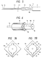
- FIGS. 5, 6 and 7 are diagrams illustrating two mechanisms for use in the present invention, one for aligning the tip of the piercing hollow needle with that of the solid needle of the inner needle or the injection needle, and the other for adjusting the length by which the injection needle is to project from said hollow needle, with Fig. 5 being a sectional view, Fig. 6 a perspective view of the essential part and Fig. 7 showing another embodiment of the mechanism shown in Fig. 6; and Figs. 8A and 8B are rough sketches in section that illustrate a prior art technique for drug injection.
- the injection needle 7 can be attached or detached from the injection barrel 2 so that one may use a suitable type that is selected from a stock of various types having different lengths and diameters.
- a projection is provided, for example, on the outer circumference of the basal end of the connector portion 12 while, at the same time, a cutout is provided at the distal end of the hugging portion 22B (both the projection and the cutout are unshown), with them being brought into mutual engagement, thereby establishing an in-phase relationship to assure directional alignment between those inclinations.
- the piercing hollow needle 11 having the inner needle 21 thus fitted therein is allowed to penetrate the skin 61 and the muscle 62 until its distal end reaches the outer portion of the fibrous ring 66 of an intervertebral disk 63 (see Fig. 2).
- the injection needle 7 of the injection device 1 which is illustrated as an example in Fig. 1A has an extremely fine inside diameter, it is difficult to aspirate a viscous drug via the injection needle 7 for drug aspiration into the cylinder compartment 3.
- a drug aspirating hollow needle having a larger inside diameter than the injection needle 7, connect it to the injection barrel 2, aspirate the drug into the cylinder compartment 3 and thereafter replace said hollow needle with the injection needle 7.
- the connector portion 12 is designed to be adequately long compared to the length by which the needle base 8 is fitted in it so that blood or other body fluids will not immediately spread to the surrounding area even if they should flow out through the needle portion 13; in addition, the resistance or backset that would otherwise occur due to the compression of filled air when the needle base 8 is tightly fitted in the connector portion 12 is practically absent, assuring high stability when coupling the injection device 1 to the piercing hollow needle 11.
- Fig. 5 is a sectional view showing the injection needle 1 that has a graduation 16 provided in the small-diameter portion 8A at the needle base and which has the injection needle tip 14 align with the needle portion's tip 15 of the piercing hollow needle by reference to numeral zero on the scale;
- Fig. 6 is a perspective view of the essential part which illustrates the relationship of coupling between the connector portion 12 of the piercing hollow needle 11 and the small-diameter portion 8A at the needle base of the injection device 1 which are shown in Fig. 5.
- the piercing hole that remains open at the intended site is equal in diameter to the fine vestige of the injection needle and, hence, even at high internal pressure, the outflow of the drug is extremely small and, in addition, owing to rapid restoration of that hole, the outflow of blood and other body fluids is also small.
Landscapes
- Health & Medical Sciences (AREA)
- Life Sciences & Earth Sciences (AREA)
- Animal Behavior & Ethology (AREA)
- Veterinary Medicine (AREA)
- Biomedical Technology (AREA)
- Heart & Thoracic Surgery (AREA)
- Anesthesiology (AREA)
- Engineering & Computer Science (AREA)
- Surgery (AREA)
- General Health & Medical Sciences (AREA)
- Public Health (AREA)
- Hematology (AREA)
- Pathology (AREA)
- Nuclear Medicine, Radiotherapy & Molecular Imaging (AREA)
- Vascular Medicine (AREA)
- Medical Informatics (AREA)
- Molecular Biology (AREA)
- Infusion, Injection, And Reservoir Apparatuses (AREA)
Applications Claiming Priority (4)
| Application Number | Priority Date | Filing Date | Title |
|---|---|---|---|
| JP324750/92 | 1992-11-10 | ||
| JP32475092 | 1992-11-10 | ||
| JP32475092 | 1992-11-10 | ||
| PCT/JP1993/001638 WO1994011042A1 (fr) | 1992-11-10 | 1993-11-10 | Injecteur et son utilisation |
Publications (3)
| Publication Number | Publication Date |
|---|---|
| EP0699449A4 EP0699449A4 (fr) | 1995-08-08 |
| EP0699449A1 true EP0699449A1 (fr) | 1996-03-06 |
| EP0699449B1 EP0699449B1 (fr) | 2001-06-20 |
Family
ID=18169268
Family Applications (1)
| Application Number | Title | Priority Date | Filing Date |
|---|---|---|---|
| EP93924803A Expired - Lifetime EP0699449B1 (fr) | 1992-11-10 | 1993-11-10 | Injecteur et son utilisation |
Country Status (6)
| Country | Link |
|---|---|
| US (1) | US5827236A (fr) |
| EP (1) | EP0699449B1 (fr) |
| JP (1) | JP3464220B2 (fr) |
| AU (1) | AU673703B2 (fr) |
| DE (1) | DE69330374T2 (fr) |
| WO (1) | WO1994011042A1 (fr) |
Cited By (2)
| Publication number | Priority date | Publication date | Assignee | Title |
|---|---|---|---|---|
| US6547769B2 (en) | 1999-12-20 | 2003-04-15 | Tricardia Llc | Catheter apparatus with weeping tip and method of use |
| US6969373B2 (en) | 2001-04-13 | 2005-11-29 | Tricardia, Llc | Syringe system |
Families Citing this family (45)
| Publication number | Priority date | Publication date | Assignee | Title |
|---|---|---|---|---|
| US6241734B1 (en) * | 1998-08-14 | 2001-06-05 | Kyphon, Inc. | Systems and methods for placing materials into bone |
| CA2241615A1 (fr) * | 1997-06-26 | 1998-12-26 | An-Go-Gen Inc. | Catheters |
| US7485113B2 (en) * | 2001-06-22 | 2009-02-03 | Johns Hopkins University | Method for drug delivery through the vitreous humor |
| US6830562B2 (en) | 2001-09-27 | 2004-12-14 | Unomedical A/S | Injector device for placing a subcutaneous infusion set |
| JP4125234B2 (ja) * | 2001-11-01 | 2008-07-30 | スパイン・ウェイブ・インコーポレーテッド | 椎間板間の終板の前処理のための装置及び方法 |
| ITTO20011228A1 (it) | 2001-12-28 | 2003-06-28 | Cane Srl | Contenitore per ago monouso. |
| WO2004028477A2 (fr) * | 2002-09-29 | 2004-04-08 | Surmodics, Inc. | Procede d'administration sub-retinienne d'agents therapeutiques comprenant des steroides, procede servant a concentrer une action pharmacodynamique au niveau de la choroide et de la retine et procedes associes servant a traiter et/ou a prevenir des maladies retiniennes |
| WO2004101015A2 (fr) * | 2003-05-07 | 2004-11-25 | Aleeva Medical, Inc. | Traitement du mal de dos par le retablissement de l'echange d'elements nutritifs & de dechets |
| US20060194305A1 (en) * | 2003-05-19 | 2006-08-31 | Jiahui Xia | Micro-holding pipette with an oblique opening |
| US7591805B2 (en) * | 2004-03-11 | 2009-09-22 | Merit Medical Systems, Inc. | Integral flushing device |
| ATE424228T1 (de) | 2004-03-26 | 2009-03-15 | Unomedical As | Infusionsset |
| WO2006014484A2 (fr) * | 2004-07-02 | 2006-02-09 | Surmodics, Inc. | Procedes et dispositifs pour le traitement d'affections oculaires |
| US8062250B2 (en) | 2004-08-10 | 2011-11-22 | Unomedical A/S | Cannula device |
| US7867199B2 (en) | 2004-12-10 | 2011-01-11 | Unomedical A/S | Inserter |
| CN101098728B (zh) | 2005-02-25 | 2011-02-09 | 泰尔茂株式会社 | 穿刺用具 |
| US7985199B2 (en) | 2005-03-17 | 2011-07-26 | Unomedical A/S | Gateway system |
| US8003124B2 (en) * | 2005-04-08 | 2011-08-23 | Surmodics, Inc. | Sustained release implants and methods for subretinal delivery of bioactive agents to treat or prevent retinal disease |
| ATE480278T1 (de) * | 2005-09-12 | 2010-09-15 | Unomedical As | Einfürungssystem für ein infusionsset mit einem ersten und zweiten federeinheit |
| USD655807S1 (en) | 2005-12-09 | 2012-03-13 | Unomedical A/S | Medical device |
| DE602006006477D1 (de) | 2005-12-23 | 2009-06-04 | Unomedical As | Verabreichungsgerät |
| AU2007219546B8 (en) | 2006-02-28 | 2012-07-05 | Unomedical A/S | Inserter for infusion part and infusion part provided with needle protector |
| WO2007140783A2 (fr) | 2006-06-07 | 2007-12-13 | Unomedical A/S | Appareil à insérer |
| KR20090028701A (ko) | 2006-06-09 | 2009-03-19 | 우노메디컬 에이/에스 | 장착 패드 |
| RU2443436C2 (ru) | 2006-08-02 | 2012-02-27 | Уномедикал А/С | Канюльное и доставочное устройство |
| EP1917990A1 (fr) | 2006-10-31 | 2008-05-07 | Unomedical A/S | Ensemble de perfusion |
| EP2155311B1 (fr) | 2007-06-20 | 2013-01-02 | Unomedical A/S | Procédé et dispositif de fabrication d'un cathéter |
| EP2185224A1 (fr) | 2007-07-03 | 2010-05-19 | Unomedical A/S | Dispositif d'introduction présentant deux états d'équilibre stables |
| RU2010104457A (ru) | 2007-07-10 | 2011-08-20 | Уномедикал А/С (Dk) | Устройство ввода с двумя пружинами |
| NZ582226A (en) | 2007-07-18 | 2011-12-22 | Unomedical As | Insertion device with a pivoting action from a first to a second position and longitudinal action to a third position in the direction of insertion. |
| RU2010137844A (ru) | 2008-02-13 | 2012-03-20 | Уномедикал А/С (Dk) | Уплотнение между канюльной частью и путем прохождения текучей среды |
| CA2715667A1 (fr) | 2008-02-20 | 2009-08-27 | Unomedical A/S | Dispositif d'insertion munie d'une piece mobile dans le sens horizontal |
| CN102256657A (zh) | 2008-12-22 | 2011-11-23 | 犹诺医药有限公司 | 包括粘合垫的医疗器械 |
| WO2010093662A2 (fr) * | 2009-02-10 | 2010-08-19 | Psivida Us, Inc. | Ensemble de trocart oculaire |
| JP2013500099A (ja) | 2009-07-30 | 2013-01-07 | ウノメディカル・アー/エス | 水平方向の可動部材を備えた挿入デバイス |
| CN102548598B (zh) | 2009-08-07 | 2014-09-17 | 犹诺医药有限公司 | 具有传感器和一个或多个插管的传送装置 |
| CA2792138A1 (fr) | 2010-03-30 | 2011-10-06 | Unomedical A/S | Dispositif medical |
| EP2433663A1 (fr) | 2010-09-27 | 2012-03-28 | Unomedical A/S | Système d'insertion |
| EP2436412A1 (fr) | 2010-10-04 | 2012-04-04 | Unomedical A/S | Canule d'arroseur |
| EP2763723B1 (fr) | 2011-10-05 | 2016-04-13 | Unomedical A/S | Introducteur pour insertion simultanée de plusieurs éléments transcutanés |
| EP2583715A1 (fr) | 2011-10-19 | 2013-04-24 | Unomedical A/S | Système de tube de perfusion et procédé de fabrication |
| US9440051B2 (en) | 2011-10-27 | 2016-09-13 | Unomedical A/S | Inserter for a multiplicity of subcutaneous parts |
| RU2687176C2 (ru) | 2014-09-11 | 2019-05-07 | Айпоинт Фармасьютикалз Юэс, Инк. | Инъекционное устройство |
| USD851755S1 (en) | 2015-10-22 | 2019-06-18 | Eyepoint Pharmaceuticals Us, Inc. | Ocular inserter |
| CN106420016A (zh) * | 2016-11-10 | 2017-02-22 | 矫文捷 | 一种用于肺部结节术前ct引导下定位的穿刺针 |
| CN107596509B (zh) * | 2017-09-19 | 2022-07-08 | 李奇元 | 一种安全注射器用针头装置 |
Family Cites Families (15)
| Publication number | Priority date | Publication date | Assignee | Title |
|---|---|---|---|---|
| GB169702A (en) * | 1921-09-24 | 1922-07-13 | Schmidt Otto | Improvements in hypodermic needles |
| US2219605A (en) * | 1938-06-06 | 1940-10-29 | Turkel Henry | Device for performing a biopsy |
| US3792703A (en) * | 1972-07-10 | 1974-02-19 | Deseret Pharma | Catheter placement unit |
| US4013080A (en) * | 1974-10-03 | 1977-03-22 | Froning Edward C | Cannula connector and direction indicator means for injection system |
| US4405307A (en) * | 1981-12-10 | 1983-09-20 | Taylor Alan N | Needle assembly and method for fabricating same |
| US4511356A (en) * | 1983-02-22 | 1985-04-16 | Edward C. Froning | Cannula, obturator, stylet and needle hub connectors for lumbar disc puncture |
| EP0306606A1 (fr) * | 1985-05-10 | 1989-03-15 | B. Braun-SSC AG | Seringue d'injection à jeter à deux canules |
| DK164570C (da) * | 1985-10-30 | 1992-12-07 | Luebbers Heiko | Instrumentsaet til biopsi |
| US5026350A (en) * | 1986-10-09 | 1991-06-25 | Hakko Electric Machine Works Co., Ltd. | Set of double needles for injecting liquid medicine |
| DE3680919D1 (de) * | 1986-10-09 | 1991-09-19 | Hakko Electric Machine Works C | Doppelnadel-set zum injizieren eines fluessigen medikaments. |
| US4844087A (en) * | 1987-09-16 | 1989-07-04 | Garg Rakesh K | First method for using cannula including a valve structure and associated instrument element |
| JPH0344208Y2 (fr) * | 1987-11-17 | 1991-09-17 | ||
| JPH0542839Y2 (fr) * | 1988-06-24 | 1993-10-28 | ||
| US4973312A (en) * | 1989-05-26 | 1990-11-27 | Andrew Daniel E | Method and system for inserting spinal catheters |
| US5147314A (en) * | 1991-11-18 | 1992-09-15 | Vaillancourt Vincent L | Apparatus for introducing at least one of a catheter and a guide wire into a body cavity |
-
1993
- 1993-11-10 JP JP51192294A patent/JP3464220B2/ja not_active Expired - Fee Related
- 1993-11-10 EP EP93924803A patent/EP0699449B1/fr not_active Expired - Lifetime
- 1993-11-10 US US08/403,693 patent/US5827236A/en not_active Expired - Lifetime
- 1993-11-10 AU AU54334/94A patent/AU673703B2/en not_active Expired
- 1993-11-10 DE DE69330374T patent/DE69330374T2/de not_active Expired - Lifetime
- 1993-11-10 WO PCT/JP1993/001638 patent/WO1994011042A1/fr not_active Ceased
Cited By (5)
| Publication number | Priority date | Publication date | Assignee | Title |
|---|---|---|---|---|
| US6547769B2 (en) | 1999-12-20 | 2003-04-15 | Tricardia Llc | Catheter apparatus with weeping tip and method of use |
| US6855132B2 (en) | 1999-12-20 | 2005-02-15 | Tricardia, Llc | Apparatus with weeping tip and method of use |
| US6949087B2 (en) | 1999-12-20 | 2005-09-27 | Tricardia, Llc | Apparatus with weeping tip and method of use |
| US7252654B2 (en) | 1999-12-20 | 2007-08-07 | Tricardia, Llc | Apparatus with weeping tip and method of use |
| US6969373B2 (en) | 2001-04-13 | 2005-11-29 | Tricardia, Llc | Syringe system |
Also Published As
| Publication number | Publication date |
|---|---|
| DE69330374D1 (de) | 2001-07-26 |
| EP0699449B1 (fr) | 2001-06-20 |
| AU673703B2 (en) | 1996-11-21 |
| US5827236A (en) | 1998-10-27 |
| AU5433494A (en) | 1994-06-08 |
| EP0699449A4 (fr) | 1995-08-08 |
| JP3464220B2 (ja) | 2003-11-05 |
| DE69330374T2 (de) | 2002-05-02 |
| WO1994011042A1 (fr) | 1994-05-26 |
Similar Documents
| Publication | Publication Date | Title |
|---|---|---|
| EP0699449B1 (fr) | Injecteur et son utilisation | |
| JPWO1994011042A1 (ja) | 注射具及びその使用方法 | |
| DE60202315T2 (de) | Flexible Nadelvorrichtung | |
| US20030181863A1 (en) | Microneedle adapter | |
| US5288291A (en) | Method and apparatus for simultaneously injecting a liquid and a transponder into an animal | |
| RU2080882C1 (ru) | Шприц | |
| US4349023A (en) | Epidural needle catheter and adapter | |
| US5738660A (en) | Percutaneous port catheter assembly and method of use | |
| CA2156695C (fr) | Bouton-adaptateur pour ajuster la dose d'un stylo distributeur de medicament | |
| US5569217A (en) | Percutaneous port catheter assembly and method of use | |
| US5501664A (en) | Subcutaneous drug delivery device | |
| US3911916A (en) | Sequential injection syringe | |
| DE69728048T2 (de) | Vorgefüllte medizinische injektionsvorrichtung mit zurückziehbarer nadel | |
| EP0956879A1 (fr) | Dispositif de perfusion pour délivrer un agent de manière sous-cutané | |
| US6379328B1 (en) | Disposable syringe | |
| EP1133382B1 (fr) | Procede de formation d'une decoupe dans un element refermable pour un point d'injection sans aiguille | |
| JP2004358276A (ja) | 自己鈍化針カニューレ装置及びその集成方法 | |
| JP3345317B2 (ja) | 内視鏡用注射具 | |
| CN115361986A (zh) | 医疗用注射器芯杆以及医疗用指托 | |
| CN106998992A (zh) | 内窥镜用护套和内窥镜用注射定位器具 | |
| KR20210048662A (ko) | 주사기 | |
| JP3300343B2 (ja) | 2個のカニューレを有するアプリケーター | |
| CA2144450C (fr) | Instrument d'injection et methode d'utilisation correspondante | |
| US2693184A (en) | Hypodermic syringe and aspirating ampoule thereof | |
| WO2021231280A1 (fr) | Dispositif hypodermique avec un ensemble d'aiguilles hypodermiques |
Legal Events
| Date | Code | Title | Description |
|---|---|---|---|
| A4 | Supplementary search report drawn up and despatched | ||
| AK | Designated contracting states |
Kind code of ref document: A4 Designated state(s): DE FR GB |
|
| PUAI | Public reference made under article 153(3) epc to a published international application that has entered the european phase |
Free format text: ORIGINAL CODE: 0009012 |
|
| 17P | Request for examination filed |
Effective date: 19950313 |
|
| AK | Designated contracting states |
Kind code of ref document: A1 Designated state(s): DE FR GB |
|
| 17Q | First examination report despatched |
Effective date: 19990618 |
|
| GRAG | Despatch of communication of intention to grant |
Free format text: ORIGINAL CODE: EPIDOS AGRA |
|
| GRAG | Despatch of communication of intention to grant |
Free format text: ORIGINAL CODE: EPIDOS AGRA |
|
| GRAH | Despatch of communication of intention to grant a patent |
Free format text: ORIGINAL CODE: EPIDOS IGRA |
|
| RBV | Designated contracting states (corrected) |
Designated state(s): DE FR GB |
|
| GRAH | Despatch of communication of intention to grant a patent |
Free format text: ORIGINAL CODE: EPIDOS IGRA |
|
| GRAA | (expected) grant |
Free format text: ORIGINAL CODE: 0009210 |
|
| AK | Designated contracting states |
Kind code of ref document: B1 Designated state(s): DE FR GB |
|
| REF | Corresponds to: |
Ref document number: 69330374 Country of ref document: DE Date of ref document: 20010726 |
|
| ET | Fr: translation filed | ||
| REG | Reference to a national code |
Ref country code: GB Ref legal event code: IF02 |
|
| PLBE | No opposition filed within time limit |
Free format text: ORIGINAL CODE: 0009261 |
|
| STAA | Information on the status of an ep patent application or granted ep patent |
Free format text: STATUS: NO OPPOSITION FILED WITHIN TIME LIMIT |
|
| 26N | No opposition filed | ||
| REG | Reference to a national code |
Ref country code: FR Ref legal event code: CA |
|
| PGFP | Annual fee paid to national office [announced via postgrant information from national office to epo] |
Ref country code: DE Payment date: 20121107 Year of fee payment: 20 Ref country code: FR Payment date: 20121130 Year of fee payment: 20 |
|
| PGFP | Annual fee paid to national office [announced via postgrant information from national office to epo] |
Ref country code: GB Payment date: 20121107 Year of fee payment: 20 |
|
| REG | Reference to a national code |
Ref country code: DE Ref legal event code: R071 Ref document number: 69330374 Country of ref document: DE |
|
| REG | Reference to a national code |
Ref country code: GB Ref legal event code: PE20 Expiry date: 20131109 |
|
| PG25 | Lapsed in a contracting state [announced via postgrant information from national office to epo] |
Ref country code: GB Free format text: LAPSE BECAUSE OF EXPIRATION OF PROTECTION Effective date: 20131109 Ref country code: DE Free format text: LAPSE BECAUSE OF EXPIRATION OF PROTECTION Effective date: 20131112 |